Kenwood TK-790 Service Manual
Hide thumbs
Also See for TK-790:
- Instruction manual (23 pages) ,
- Specifications (2 pages) ,
- Instruction manual (23 pages)
Table of Contents
Advertisement
Quick Links
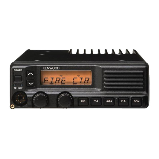
VHF FM TRANSCEIVER
TK-790/
TK-790H
SERVICE MANUAL
This service manual applies to products with 30300001 or subsequent serial numbers. (KCH-10 and KCH-11 are applicable to
the productions June 2001 and after.)
In terms of the products with the serial numbers earier than 30300001, refer to the TK-790/(B)/H(B) service manual as per
part No. B51-8438-00 and the TK-790(B) service manual as per part No. B51-8456-00.
TK-790 or TK-790(B) with KCH-10
Cabinet (Lower)
(A01-2162-02)
TK-790H(B)
Cabinet (Lower)
(A01-2164-01)
(
)
B
(
)
B
REVISED
Cabinet (Upper)
(A01-2161-02)
Knob
(K29-4664-04) x 2
Knob
(K29-4664-04) x 2
© 2001-6 PRINTED IN JAPAN
B51-8438-10 ( N ) 1234
Panel assy
(A62-0606-13)
Panel assy
(A62-0607-13)
Cabinet (Upper)
(A01-2163-01)
Advertisement
Table of Contents

Related Manuals for Kenwood TK-790


Summary of Contents for Kenwood TK-790
- Page 1 This service manual applies to products with 30300001 or subsequent serial numbers. (KCH-10 and KCH-11 are applicable to the productions June 2001 and after.) In terms of the products with the serial numbers earier than 30300001, refer to the TK-790/(B)/H(B) service manual as per part No. B51-8438-00 and the TK-790(B) service manual as per part No. B51-8456-00.
-
Page 2: Table Of Contents
DISPLAY UNIT (X54-3190-20) : KCH-10 ..............79 DISPLAY UNIT (X54-3200-20) : KCH-11 ..............81 CONTROL UNIT (X57-5610-XX) (B/3) ..............87 FINAL UNIT (X57-5610-XX) (C/3) : TK-790/(B) ............97 TX-RX UNIT (X57-5610-XX) (A/3) ................. 101 FINAL UNIT (X45-3560-10) : TK-790H(B) .............. 113 BLOCK DIAGRAM ...................... -
Page 3: General
Your KENWOOD dealer can help you select an antenna sys- tion. Transmitter frequency, deviation, and power output tem that will best serve your particular needs. -
Page 4: System Set-Up
TK-790/ SYSTEM SET-UP Before Reading About System Set-up The TK-790(B)/H(B) is a transceiver main unit (without a 3. Remotely control one radio with two controllers. (Form panel or speaker) that you complete by adding options. : Radio + KRK-6DH + KCH-10/11 (two) + KCT-22M/M2/... -
Page 5: Operating Features
TK-790/ OPERATING FEATURES (1) POWER Switch 1. Controls and Functions Press to turn the power ON and OFF. 1-1. Basic Function Panel (2) TX/BUSY Indicator The TX Indicator (Red LED) shows that you are transmit- (19) ting. The BUSY Indicator (Green LED) shows that the channel is in use. -
Page 6: Operating Features
TK-790/ OPERATING FEATURES Function Description Note Function Description Note [ ] : Key top name [ ] : Key top name Channel Switches the display between Speaker 1-2 Each speaker audio can be Dual HEAD Name [AN] Group-Channel No. and Group... -
Page 7: Scan Operation
TK-790/ OPERATING FEATURES 2. Receive Description Note (27) C Lights when [AUXC] is pressed. (1) To turn on the RADIO: Press the Power Switch. The display and graphics illumi- The PF Port that is programmed nate to indicate the RADIO is ON. - Page 8 TK-790/ OPERATING FEATURES (1) The scan feature is initiated by pressing the [SCN] Key. 6. Deleting Channels and Groups from the (2) A single confirmation tone sounds, and scanning starts. If Scan Sequence there is only one or no added channels, an error tone will sound and scanning will not start.
- Page 9 TK-790/ OPERATING FEATURES 10. Public Address (PA) CASE1 : HC has been set as “HC (Fixed)” Non-Scan Scanning Scan Public Address amplifies the microphone audio, and out- puts it through a PA speaker. PA is activated by pressing the Mode temporary [PA] Key.
- Page 10 TK-790/ OPERATING FEATURES 17. Option Board (OPT) Display TX/BUSY Panel Keys Microphone backlight backlight Keys backlight If an optional Scrambler board has been installed in the RADIO, Scrambler is activated by pressing the [OPT] Key. A Default High High High High confirmation tone sounds, and the OPT icon is displayed.
-
Page 11: Tone Signalling
TK-790/ OPERATING FEATURES 25. Busy Channel Lockout (BCL), BCL Override 29. Signalling AND/OR T h e B u s y C h a n n e l L o c k o u t f u n c t i o n p r e v e n t s... - Page 12 TK-790/ OPERATING FEATURES 36-2. PF Output Port 33. Minimum Volume Pressing [AUXA] once → Low, Pressing [A] AUX A When the Volume Knob is adjusted fully counterclock- [AUXA] again → OPEN-COLLECTOR wise, the audio level is set to the Minimum Volume level which is programmed by the FPU.
-
Page 13: Power On Text
DOS version 3.1 or later on an IBM-PC/XT, AT, or PS2 or compatible machine. • Emergency Call Fleet The data can be input to or read from TK-790 and edited The emergency fleet number when you select MSK in on the screen. The programmed or edited data can be the emergency type. - Page 14 TK-790/ OPERATING FEATURES 43. PC Tuning Mode Mode Function User mode Customer use this mode When making adjustment while in PC tuning mode, modify the KPG-43 programming interface cable as de- PC mode Communication between the radio and scribed below.
- Page 15 TK-790/ OPERATING FEATURES 44-3. Group Clone 44. Clone Modes 1. Enter the group clone mode from the clone mode with There are two clone modes : "All Clone Mode", in which [Up/Down] knob. all data programmed in one transceiver with the "FPU" is 2.
- Page 16 • Connection with remote kit Modification of the radio to use KRK-5, KRK-6DH, KRK- 7DB, or KRK-8DBH 2. Front Panel Kit (KCH-10, KCH-11) 2-2. Connection with TK-790(B)/H(B) 1. Remove the upper and lower halves of the case of the AUX A TK-790(B)/H(B).
-
Page 17: Installation
TK-790/ INSTALLATION 3-2. Voice scrambler board connection • Modification 1. Remove the upper half of the case of the TK-790. 2. Remove R515 and R604 on the control unit (X57-561 B/ 3) (Refer to page 21). • Connection The functions of pins of CN508 on the control unit (X57- 561 B/3) are shown in the figure. - Page 18 6. Reinstall the upper half of the case. Note : Since the TK-790 uses a BTL audio amplifier, do not Note : If the KCT-18 is used for the KRK-8DBH, use the 9-pin ground the speaker output pin.
- Page 19 TK-790/ INSTALLATION 6-1. Connection for the KES-4 with the TK-790 6-2. Connection for the KES-4 with the remote kit • When taking the AF output from the accessory (KRK-5, KRK-6DH, KRK-7DB, KRK-8DBH) connector (9-pin) on the rear of the radio...
- Page 20 100mA. The maximum available current can below. be increased to 1A by installing a relay. 1. Remove the upper half of the case of the TK-790. KRK-5 KRK-6DH KRK-7DB KRK-8DBH 2.
- Page 21 TK-790/ INSTALLATION R661 CONTROL UNIT (X57 B/3) R743 Connection with Component side view the remote kit Ignition sense (Page 20) cable (KCT-18) R742 (Page 18) R504 Ignition sense cable (KCT-18) (Page 18) R506 R546 Connection with the remote kit R705...
- Page 22 TK-790/ DISASSEMBLY FOR REPAIR (TK-790/(B)) 1. Removing the Case and Shield Cover 3. Removing the Final Unit (X57-561 C/3) 1. Remove the 9 screws ( ), and remove the upper and 1. Remove the 2 screws ( ) holding the power module to lower halves of the case.
-
Page 23: Disassembly For Repair
TK-790/ DISASSEMBLY FOR REPAIR (TK-790H(B)) 1. Removing the Case and Shield Cover 3. Removing the Final Unit (X45-356) 1. Remove the 12 screws ( ), and remove the upper and 1. Remove the 2 hexagonal bosses ( lower halves of the case. (Remove the 6 screws holding 2. -
Page 24: Disassembly For Repair
TK-790/ DISASSEMBLY FOR REPAIR 4. Removing the Control Unit (X57-561 B/3) 5. Removing the Accessory Connector on the Rear 1. Remove the 8 screws ( 2. With a screwdriver, remove the 2 leaf springs holding the 1. Confirm that the screw holding +DC cable (red) and the ICs to the frame ( screw holding –DC cable (black) of the final unit are re-... - Page 25 TK-790/ DISASSEMBLY FOR REPAIR 6. Disassembly of the Display Unit 7. Disassembly of the Display Unit (X54-3190) : KCH-10 (X54-3200) : KCH-11 1. Pull out the VOL and UP/DOWN knobs ( 1. Pull out the VOL and UP/DOWN knobs ( 2.
-
Page 26: Circuit Description
TH1, DC SW Q1 is made to re- duce the reference voltage of the PC tuned. This also leads 1-3. Final amplifier section (X57 C/3) : TK-790/(B) to the transmitter output power being reduced. Antenna switching is done by a relay K1 with 8R. -
Page 27: Circuit Description
Pass bandwidth switched to the front-end of the receiver system via a re- ± 25kHz or less at 40dB Attenuation bandwidth ceive/transmit switch (switching diode D3 and D4 : TK-790/ Ripple 1.0dB or less (B), switching relay K1 : TK-790H(B)). - Page 28 5. VCO/PLL Circuit The output from IC101 enters FM IC again, then passed The VCO of TK-790 consists of two VCO circuits which through a band-pass filter. The noise component output one oscillates the transmit signal with Q306 and the other from IC101 is amplified by Q109 and rectified by D103 to does the first local receive signal with Q305.
- Page 29 TK-790/ CIRCUIT DESCRIPTION 6. Control Circuit Q519 The control unit consists of microprocessor IC and its D507 Q543 peripheral circuits. It controls the TX-RX unit and transfers data to and from the control unit. The CPU (IC516) mainly performs the following :...
-
Page 30: Display Unit
790(B)/H(B) comes in two models : KCH-10 and KCH-11 and sent to the control unit. Data is displayed on the 13- segments, 8-digits LCD and 7-segments, 3-digits LCD by 8-1. KCH-10 (Contain : TK-790) the built-in LCD driver. This display unit consists of a CPU (IC4) containing the LCD driver, a reset IC (IC2), 5V AVR (IC1), EEPROM (IC3), •... - Page 31 TK-790/ CIRCUIT DESCRIPTION 8-2. KCH-11 • Dimmer function This display unit consists of a CPU (IC4) a reset IC (IC2), From the control of the CPU’s DM1/DM2 port, you can 5V AVR (IC1), EEPROM (IC3), and other components. switch the LCD/KEY backlight, busy/TX LED, or the optional KMC-28 key backlight as shown in the following table.
-
Page 32: Semiconductor Data
TK-790/ SEMICONDUCTOR DATA Microprocessor : 784214GCXXX8EU (Control Unit IC516) • Terminal function Pin No. Pin name Action Pin No. Pin name Action FCLR Modem FCLR RXD1 Serial interface RXD Common CLOCK TXD1 Serial interface TXD D/A converter CS Modem STB... -
Page 33: Semiconductor Data
TK-790/ SEMICONDUCTOR DATA Microprocessor : 78064GCXXX8EU (Display Unit IC4) • Terminal function Pin No. Pin name Action Pin No. Pin name Action MIC PTT L : ON, H : OFF Not used [MON] key L : ON, H : OFF... - Page 34 TK-790/ SEMICONDUCTOR DATA • Block diagram • Shift register 2 on control unit (IC517) Pin No. Port Name Action MIC mute H : Mute, L : Unmute Audio line SW RX BPF← →DE-EMP mute switch –INV 1 DET line SW DET← →RX BPF kΩ...
- Page 35 MAIN MEMORY No connect (240K BYTES) OPTIONAL BOOT BLOCK (8K BYTES) Power Amplifier : M68702H (Final Unit IC1) TK-790/(B) K type : M68702L (Final Unit IC1) TK-790(B) K2 type • Equivalent circuit F.B. 1 : Input 2 : 1st stage power supply...
-
Page 36: Description Of Components
Q309 DC switch Off when TX Q310 Buffer amplifier TX-RX Unit (X57-5610-XX) (A/3) Q311,312 Amplifier -10 : TK-790/(B) K -11 : TK-790(B) K2 -12 : TK-790H(B) K D101 DC switch On when TX Ref. No. Use/Function Operation/Condition D102 BPF tuning... -
Page 37: Description Of Components
TK-790/ DESCRIPTION OF COMPONENTS Control Unit (X57-5610-XX) (B/3) Ref. No. Use/Function Operation/Condition -10 : TK-790/(B) K -11 : TK-790(B) K2 -12 : TK-790H(B) K Q523 DC switch Serial data inverter Ref. No. Use/Function Operation/Condition Q524 DC switch Serial data transmitter... - Page 38 TK-790/ DESCRIPTION OF COMPONENTS Display Unit (X54-3190-20) : KCH-10 Display Unit (X54-3200-20) : KCH-11 Ref. No. Use/Function Operation/Condition Ref. No. Use/Function Operation/Condition Input : SB Output : 5V Input : SB Output : 5V Reset Reset EEPROM EEPROM CPU/LCD driver...
-
Page 39: Parts List
TK-790/ PARTS LIST New Parts. indicates safety critical components. L : Scandinavia K : USA P : Canada Parts without Parts No. are not supplied. Y : PX (Far East, Hawaii) T : England E : Europe Les articles non mentionnes dans le Parts No. ne sont pas fournis. -
Page 40: Parts List
C114 CC73GCH1H100D CHIP C 10PF C114 CC73GCH1H150J CHIP C 15PF C116 CC73GCH1H020C CHIP C 2.0PF TX-RX UNIT (X57-5610-XX) -10 : TK-790/(B) K -11 : TK-790(B) K2 C117 CC73GCH1H680J CHIP C 68PF CK73GB1H102K CHIP C 1000PF C118 CC73GCH1H080D CHIP C 8.0PF... - Page 41 TK-790/ PARTS LIST TX-RX UNIT (X57-5610-XX) : TK-790/(B) Desti- Desti- Ref. No. Address Parts No. Description Ref. No. Address Parts No. Description parts nation parts nation C177 CK73GB1H102K CHIP C 1000PF C328 CC73GCH1H180G CHIP C 18PF C178 CK73GB1H103K CHIP C 0.010UF...
- Page 42 TK-790/ PARTS LIST TX-RX UNIT (X57-5610-XX) : TK-790/(B) Desti- Desti- Ref. No. Address Parts No. Description Ref. No. Address Parts No. Description parts nation parts nation C552 CC73GCH1H470J CHIP C 47PF C626 C92-0004-05 CHIP-TAN 1.0UF 16WV C553,554 CK73FB1E104K CHIP C 0.10UF...
- Page 43 TK-790/ PARTS LIST TX-RX UNIT (X57-5610-XX) : TK-790/(B) Desti- Desti- Ref. No. Address Parts No. Description Ref. No. Address Parts No. Description parts nation parts nation L34-4519-05 AIR-CORE COIL RK73FB2A101J CHIP R 1/10W L34-4523-05 AIR-CORE COIL RK73GB1J223J CHIP R 1/16W...
- Page 44 TK-790/ PARTS LIST TX-RX UNIT (X57-5610-XX) : TK-790/(B) Desti- Desti- Ref. No. Address Parts No. Description Ref. No. Address Parts No. Description parts nation parts nation R205 RK73GB1J222J CHIP R 2.2K 1/16W R358 RK73GB1J331J CHIP R 1/16W R206 RK73GB1J103J CHIP R...
- Page 45 TK-790/ PARTS LIST TX-RX UNIT (X57-5610-XX) : TK-790/(B) Desti- Desti- Ref. No. Address Parts No. Description Ref. No. Address Parts No. Description parts nation parts nation R575,576 RK73GB1J104J CHIP R 100K 1/16W R665 RK73GB1J104J CHIP R 100K 1/16W R577 RK73GB1J122J CHIP R 1.2K...
- Page 46 TK-790/ PARTS LIST TX-RX UNIT (X57-5610-XX) : TK-790/(B) TK-790H(B) Desti- Desti- Ref. No. Address Parts No. Description Ref. No. Address Parts No. Description parts nation parts nation D301-304 1SV282 VARIABLE CAPACITANCE DIODE Q107 2SC4215(Y) TRANSISTOR D305 1SV214 VARIABLE CAPACITANCE DIODE...
- Page 47 TK-790/ PARTS LIST TK-790H(B) FINAL UNIT (X45-3560-10) : TK-790H(B) Desti- Desti- Ref. No. Address Parts No. Description Ref. No. Address Parts No. Description parts nation parts nation E31-3301-05 LEAD WIRE WITH MINIPIN PLUG (RA/DO) C22,23 CM73F2H681J CHIP C 680PF E37-0709-05...
- Page 48 TK-790/ PARTS LIST FINAL UNIT (X45-3560-10) : TK-790H(B) TX-RX UNIT (X57-5610-12) : TK-790H(B) Desti- Desti- Ref. No. Address Parts No. Description Ref. No. Address Parts No. Description parts nation parts nation RK73FB2A392J CHIP R 3.9K 1/10W C125 CK73GB1H103K CHIP C 0.010UF...
- Page 49 TK-790/ PARTS LIST TX-RX UNIT (X57-5610-12) : TK-790H(B) Desti- Desti- Ref. No. Address Parts No. Description Ref. No. Address Parts No. Description parts nation parts nation C215 CK73FB1E104K CHIP C 0.10UF C525 CK73FB1E683K CHIP C 0.068UF C216 CK73GB1C473K CHIP C 0.047UF...
- Page 50 TK-790/ PARTS LIST TX-RX UNIT (X57-5610-12) : TK-790H(B) Desti- Desti- Ref. No. Address Parts No. Description Ref. No. Address Parts No. Description parts nation parts nation C600 C92-0507-05 CHIP-TAN 4.7UF 6.3WV CN102,103 E40-5538-05 PIN ASSY C601 CK73GB1H102K CHIP C 1000PF...
- Page 51 TK-790/ PARTS LIST TX-RX UNIT (X57-5610-12) : TK-790H(B) Desti- Desti- Ref. No. Address Parts No. Description Ref. No. Address Parts No. Description parts nation parts nation R101 RK73GB1J470J CHIP R 1/16W R209 RK73GB1J560J CHIP R 1/16W R102 RK73GB1J472J CHIP R 4.7K...
- Page 52 TK-790/ PARTS LIST TX-RX UNIT (X57-5610-12) : TK-790H(B) Desti- Desti- Ref. No. Address Parts No. Description Ref. No. Address Parts No. Description parts nation parts nation R505 RK73GB1J103J CHIP R 1/16W R584 RK73GB1J333J CHIP R 1/16W R507 RK73GB1J223J CHIP R...
- Page 53 TK-790/ PARTS LIST TX-RX UNIT (X57-5610-12) : TK-790H(B) Desti- Desti- Ref. No. Address Parts No. Description Ref. No. Address Parts No. Description parts nation parts nation R674,675 RK73GB1J472J CHIP R 4.7K 1/16W D521 DA204U DIODE R676 RK73GB1J473J CHIP R 1/16W...
- Page 54 TK-790/ PARTS LIST TX-RX UNIT (X57-5610-12) : TK-790H(B) KCH-10 DISPLAY UNIT (X54-3190-20) : KCH-10 Desti- Desti- Ref. No. Address Parts No. Description Ref. No. Address Parts No. Description parts nation parts nation Q509-513 DTC144EUA DIGITAL TRANSISTOR DISPLAY UNIT (X54-3190-20) : KCH-10...
- Page 55 TK-790/ PARTS LIST DISPLAY UNIT (X54-3190-20) : KCH-10 KCH-11 DISPLAY UNIT (X54-3200-20) : KCH-11 Desti- Desti- Ref. No. Address Parts No. Description Ref. No. Address Parts No. Description parts nation parts nation RK73GB1J822J CHIP R 8.2K 1/16W DISPLAY UNIT (X54-3200-20) : KCH-11...
- Page 56 TK-790/ PARTS LIST DISPLAY UNIT (X54-3200-20) : KCH-11 Desti- Desti- Ref. No. Address Parts No. Description Ref. No. Address Parts No. Description parts nation parts nation R31-0607-05 VARIABLE RESISTOR (10K) S40-1420-05 TACT SWITCH S2,3 S70-0410-15 TACT SWITCH S5-15 S70-0410-15 TACT SWITCH...
- Page 57 TK-790/ EXPLODED VIEW (TK-790/(B)) : N09-2292-05 M3 x 6 (F) : N32-3006-46 M3 x 6 (OC) BLK : N33-3006-45 D M3 x 6 (Bi) : N35-3006-46 M3 x 8 : N67-3008-46 G M2.6 x 6 (Br-Tap) : N87-2606-46 M2.6 x 12 (Br-Tap) : N87-2612-46...
-
Page 58: Exploded View
TK-790/ EXPLODED VIEW (TK-790H(B)) : N09-2292-05 N M3 x 6 (OC) BLK : N33-3006-45 O M3 x 6 (Bi) : N35-3006-46 M3 x 8 : N67-3008-46 Q M4 X 8 : N68-4006-46 M2.6 x 6 (Br-Tap) : N87-2606-46 M2.6 x 12 (Br-Tap) : N87-2612-46... - Page 59 TK-790/ EXPLODED VIEW (KCH-10) X54 (B/3) X54 (A/3) X54 (C/3) U M2.6 x 5 (Br-Tap) : N87-2605-46 M2.6 x 8 (Br-Tap) : N87-2608-46 W M3 x 6 (Br-Tap) : N87-3006-46 218x2 Parts with the exploded numbers larger than 700 are not supplied.
- Page 60 TK-790/ EXPLODED VIEW (KCH-11) X54 (B/2) X54 (A/2) X M2.6 x 5 (Br-Tap) : N87-2605-46 315x2 M2.6 x 8 (Br-Tap) : N87-2608-46 M3 x 8 (Br-Tap) : N87-3008-46 Parts with the exploded numbers larger than 700 are not supplied.
- Page 61 TK-790/ PACKING (TK-790/(B)) 35 Polystyrene foamed fixture (H11-0896-04) 38 Packing fixture (H12-1403-04) 12 DC cord assy (E30-3318-15) : TK-790 7 Warranty card (B46-0470-00) 8 Instruction manual 62 Microphone (B62-0970-10) (T91-0587-25) : TK-790 44 Protection bag (H25-0194-04) 37 Polystyrene foamed board...
-
Page 62: Packing
TK-790/ PACKING (TK-790H(B)) 107 Warranty card (B46-0470-00) 137 Polystyrene foamed board 108 Instruction manual (H11-0815-04) (B62-0970-10) 135 Inner packing case (H02-0604-03) 143 Protection bag (H25-2063-04) 116 Short plug (SP) (E37-0733-05) 122 Insulating cover 144 Protection bag (F29-0472-04) (H25-0103-04) 150 Band... - Page 63 TK-790/ PACKING (KCH-10) 210 Carton board (H13-1059-04) 209 Polystyrene foamed board (H11-0894-04) 225 Screw set (N99-0364-05) 213 Protection bag (H25-0117-04) 221 Knob (K29-5276-03) 222 Knob 212 Protection bag (K29-5277-03) (H25-0103-04) 223 Knob (K29-5305-03) 211 Protection bag (H25-0029-04) 219 Knob (K29-4704-04) x 5...
- Page 64 TK-790/ PACKING (KCH-11) 307 Carton board (H13-1059-04) 306 Polystyrene foamed board (H11-0894-04) 322 Screw set (N99-0364-05) 310 Protection bag (H25-0117-04) 318 Knob (K29-5276-03) 319 Knob 309 Protection bag (K29-5277-03) (H25-0103-04) 320 Knob (K29-5305-03) 308 Protection bag (H25-0029-04) 316 Knob (K29-4704-04) x 5...
- Page 65 Frequency CH up TUning item up • Test frequency channel (MHz) Signalling CH down Tuning value down K : TK-790/(B), 790H(B) K2 : TK-790(B) Signalling CH up Tuning value up Not used Tuning value backup 161.000 161.100...
-
Page 66: Adjustment
TK-790/ ADJUSTMENT • Tuning item and display (XXX : 0~255) Tuning item Basic display Full display Note Frequency FREQ_XXX FREQUENCY_XXX_ RF power _POW_XXX POWER_ _ _ _ _XXX_ RF low power LPOW_XXX LOW_POWER_XXX_ Max. deviation MXDV_XXX MAX_DEV_ _ _XXX_ Wide/Narrow item Max. - Page 67 TK-790/ ADJUSTMENT Test Equipment Required for Alignment Test Equipment Major Specifications Standard Signal Generator Frequency Range 100 to 200MHz. (SSG) Modulation Frequency modulation and external modulation. Output 0.1µV to greater than 1mV. Power Meter Input Impedance 50Ω. Operation Frequency 100 to 200MHz or more.
- Page 68 TK-790/ ADJUSTMENT Adjustment Points • TK-790/(B) • TK-790H(B) Power module FINAL UNIT X57-561 C/3 FIANL UNIT X45-356 CN104 CN201 CN203 TX-RX UNIT L112 L111 L110 CN101 X57-561 A/3 CN102 L119 L122 L118 CN103 L117 L127 L120 L123 CN202 Power module...
- Page 69 Unit Terminal Unit Parts Method equipment 1. Frequency • Frequency range (MHz) list K : 148~174 (TK-790/(B), 790H(B)) K2 : 136~156 (TK-790(B)) • Adjustment frequency (MHz) • Signalling CH No. Encode tone Decode tone None None 161.000 161.100 146.000 146.100...
- Page 70 TK-790/ ADJUSTMENT Measurement Adjustment Item Condition Specifications/Remarks Test- Unit Terminal Unit Parts Method equipment 5. BPF 1) CH-SIG : 2-1 Spectrum TX-RX CN101 TX-RX L112 Adjust the coils in Spectrum analyzer analyzer (A/3) (A/3) L111 the following order Span : 50MHz...
- Page 71 TK-790/ ADJUSTMENT Measurement Adjustment Item Condition Specifications/Remarks Test- Unit Terminal Unit Parts Method equipment • Med power 1) CH-SIG : 1-1 Power meter Rear TX-RX VR1 Maximum clockwise 47W or less model Select _POW_XXX Ammeter (C/3) (High power) in tune mode 45W adj.
- Page 72 TK-790/ ADJUSTMENT Measurement Adjustment Item Condition Specifications/Remarks Test- Unit Terminal Unit Parts Method equipment 11. DQT 1) CH-SIG : 1-2 Power meter Rear Panel PF3 key Wide/Narrow Flat the a parts. balance Select BLNC_XXX Deviation PF4 key Make the in tune mode...
- Page 73 TK-790/ ADJUSTMENT Measurement Adjustment Item Condition Specifications/Remarks Test- Unit Terminal Unit Parts Method equipment PF3 key Wide ±3.0kHz ± 0.1kHz 15. MSK 1) CH-SIG : 1-9 Power meter Rear Panel deviation Select MSDV_XXX Deviation PF4 key in tune mode meter...
-
Page 74: Terminal Function
TK-790/ TERMINAL FUNCTION Connector Terminal Terminal Connector Terminal Terminal Terminal Function Terminal Function Name Name FINAL UNIT (X45-3560-10) : TK-790H(B) CONTROL UNIT (X57-5610-XX) (B/3) Transmission drive input. W501 Output for remote speaker. Coaxial connector. Output for remote speaker. TX-RX Display... -
Page 75: Terminal Function
Serial data input/output for keypad MIC. – Earth. MIC backlight control signal output. “H” : On, “L” : Off FINAL UNIT (X57-5610-XX) (C/3) : TK-790/(B) PTT signal input. Transmission drive input. “L” : TX, “OPEN” : RX Coaxial connector. –... - Page 76 TK-790/ TERMINAL FUNCTION Connector Terminal Terminal Connector Terminal Terminal Terminal Function Terminal Function Name Name Output frequency response : Acc 25 pin D-sub connector Wide : 300~4.8kHz +1/–2dB RSSI signal output. 4.8~9.6kHz +1/–24dB Narrow : 300~4.8kHz +1/–10dB RSSI vs ANT input (Typical value) (1kHz=0dB) Auxiliary output 1 (FPU selectable).
-
Page 77: Wiring
TK-790/ TK-790/ WIRING... - Page 78 TK-790/ PC BOARD VIEWS DISPLAY UNIT (X54-3190-20) Component side view : KCH-10 (B/3) J72-0561-22 (C/3) R41 R42 R43 DOWN J72-0561-22 (A/3) Component side Foil side DISPLAY UNIT (X54-3190-20) Foil side view : KCH-10 J72-0561-22 (A/3) DOWN R41 R42 R43 J72-0561-22 (C/3)
- Page 79 TK-790/ PC BOARD VIEWS Component side Foil side DISPLAY UNIT (X54-3200-20) Component side view : KCH-11 J72-0562-12 A/2 DOWN DISPLAY UNIT (X54-3200-20) Foil side view : KCH-11 DOWN J72-0562-12 A/2...
- Page 80 TK-790/ Note : Components marked with a dot (·) are parts of pattern 1. CIRCUIT DIAGRAM...
- Page 81 TK-790/ CIRCUIT DIAGRAM Note : Components marked with a dot (·) are parts of pattern 1.
-
Page 82: Control Unit (X57-5610-Xx) (B/3)
TK-790/ PC BOARD VIEW CONTROL UNIT (X57-5610-XX) (B/3) -10 : TK-790/(B) K -11 : TK-790(B) K2 -12 : TK-790H(B) K Component side view J72-0567-42 B/3 IC514 R594 R595 R602 R663 R662 R529 C544 R530 R607 R718 R695 R661 C588 R697... - Page 83 TK-790/ PC BOARD VIEW CONTROL UNIT (X57-5610-XX) (B/3) -10 : TK-790/(B) K -11 : TK-790(B) K2 -12 : TK-790H(B) K Foil side view Q543 J72-0567-42 B/3 R740 D515 D523 D521 D516 D519 D517 D513 C698 R734 Q544 R736 C529 R744...
- Page 84 TK-790/ PC BOARD VIEW CONTROL UNIT (X57-5610-XX) (B/3) -10 : TK-790/(B) K -11 : TK-790(B) K2 -12 : TK-790H(B) K Component side view + Foil side Q543 J72-0567-42 B/3 R740 D513 D517 D519 D516 D521 D523 D515 C698 IC514 R594...
- Page 85 TK-790/ PC BOARD VIEWS FINAL UNIT (X57-5610-XX) (C/3) -10 : TK-790/(B) K -11 : TK-790(B) K2 Component side view Ref No. Address J72-0567-42 C/3 Component side Pattern 1 Pattern 2 Pattern 3 Pattern 4 Foil side FINAL UNIT (X57-5610-XX) (C/3) -10 : TK-790/(B) K -11 : TK-790(B) K2 Foil side view Ref No.
- Page 86 TK-790/ PC BOARD VIEW FINAL UNIT (X57-5610-XX) (C/3) -10 : TK-790/(B) K -11 : TK-790(B) K2 Component side view + Foil side J72-0567-42 C/3 Component side Ref No. Address Ref No. Address Ref No. Address Pattern 1 Pattern 2 Pattern 3...
-
Page 87: Tx-Rx Unit (X57-5610-Xx) (A/3)
TK-790/ PC BOARD VIEW TX-RX UNIT (X57-5610-XX) (A/3) -10 : TK-790/(B) K -11 : TK-790(B) K2 -12 : TK-790H(B) K Component side view J72-0567-42 A/3 CN203 C220 CN201 C211 CN104 C202 R202 D202 R203 C204 C133 C130 L112 L111 L110... - Page 88 TK-790/ PC BOARD VIEW TX-RX UNIT (X57-5610-XX) (A/3) -10 : TK-790/(B) K -11 : TK-790(B) K2 -12 : TK-790H(B) K Foil side view J72-0567-42 A/3 R219 L109 D105 C219 R220 C106 C184 R216 R106 C108 C102 C103 C111 C116 C186...
- Page 89 TK-790/ PC BOARD VIEW TX-RX UNIT (X57-5610-XX) (A/3) -10 : TK-790/(B) K -11 : TK-790(B) K2 -12 : TK-790H(B) K Component side view + Foil side J72-0567-42 A/3 CN203 C220 C211 R219 CN201 CN104 L109 D105 R202 C202 C219 R220...
- Page 90 TK-790/ CIRCUIT DIAGRAM Note : Components marked with a dot (·) are parts of pattern 1.
- Page 91 TK-790H CIRCUIT DIAGRAM Note : Components marked with a dot (·) are parts of pattern 1.
- Page 92 TK-790H PC BOARD VIEW FINAL UNIT (X45-3560-10) Component side view : TK-790H(B) J72-0568-02 C65 + C55 C61 Component side Foil side...
-
Page 93: Block Diagram
TK-790/ TK-790/ BLOCK DIAGRAM... -
Page 94: Specifications
Operating Temperature Range ......–30°C to +60°C (–22°F to +140°F) Dimensions & Weight ........TK-790 : 7.01" (178mm) W x 2.36" (60mm) H x 7.68" (195mm) D, 5.61lbs (2.3kg) 7.01" (178mm) W x 2.36" (60mm) H x 8.98" (228mm) D, 5.72lbs (2.6kg) with KCH-10 TK-790H : 7.01"... - Page 95 Mechelsesteenweg 418 B-1930 Zaventem, Belgium KENWOOD ELECTRONICS FRANCE S.A. 13, Boulevard Ney, 75018 Paris, France KENWOOD ELECTRONICS U.K. LIMITED KENWOOD House, Dwight Road, Watford, Herts., WD1 8EB United Kingdom KENWOOD ELECTRONICS EUROPE B.V. Amsterdamseweg 37, 1422 AC Uithoorn, The Netherlands KENWOOD ELECTRONICS ITALIA S.p.A.