
Related Manuals for Husqvarna Rider Pro 18


Summary of Contents for Husqvarna Rider Pro 18
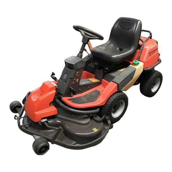
- Page 1 Operator´s manual Rider Pro 15 Rider Pro 18 Please read these instructions carefully and make sure English you understand them before using the machine.
-
Page 2: Table Of Contents
Presentation ... 11 Speed limiter ... 11 Cutting unit ... 12 Location of the controls Pro 15 ... 12 Location of the controls Pro 18 ... 13 Presentation Pro 15 ... 14 Throttle control ... 14 Choke lever ... 14 Chronometer ... -
Page 3: Introduction
INSTRUCTION Dear customer Thank you for choosing a Husqvarna Rider. Husqvarna Riders are built to a unique design with a front- mounted cutting unit and a patented rear-wheel steering system. Riders are designed for maximum efficiency even in small or confined areas. The closely grouped controls and pedal-operated hydrostatic transmission also contribute to the performance of this machine. -
Page 4: Serial Number
SAFETY INSTRUCTIONS Good service Husqvarna products are sold all over the world and only through servicing dealers. This is to ensure that you, the customer, get the best support and service. For example, before this machine was delivered it was inspected and adjusted by your dealer. -
Page 5: Explanation Of Symbols
EXPLANATION OF SYMBOLS These symbols are on the machine and in the instructions. Study them carefully so that you know what they mean. Reverse Neutral Fast Oil level Cutting height Use hearing protection Hydrostatic freewheel Noise emission to surroundings in accordance with the directive of the European Community. -
Page 6: Safety Instructions
SAFETY INSTRUCTIONS Safety instructions These instructions are for your safety. Read them carefully. WARNING! The inserted symbol means that important safety instructions need to be observed. It applies to your safety. General use • Read all the instructions in this operator’s manual and on the machine before you start it. - Page 7 SAFETY INSTRUCTIONS • Take care when rounding a fixed object, so that the blades do not hit it. Never run the machine over foreign objects. • Only use the machine in daylight or in other well-lit conditions. Keep the machine at a safe distance from holes or other irregularities in the ground.
-
Page 8: Driving On Slopes
SAFETY INSTRUCTIONS Driving on slopes Driving on slopes is one of the operations where the risk of the driver losing control of the machine or of it overturning is the greatest; this can result in serious injury or death. All slopes demand extra care. -
Page 9: Children
SAFETY INSTRUCTIONS Children • Serious accidents may occur if you fail to be on your guard for children in the vicinity of the machine. Children are often attracted to the machine and mowing. Never assume that children will remain where you last saw them. •... - Page 10 SAFETY INSTRUCTIONS • If leaks arise in the fuel system, the engine must not be started until the problem has been resolved. • Store the machine and fuel in such a way that there is no risk that leaking fuel or fumes can cause any damage.
-
Page 11: Transport
SAFETY INSTRUCTIONS • Never use the machine indoors or in spaces lacking proper ventilation. Exhaust fumes contain carbon monoxide, an odourless, poisonous and highly dangerous gas. • Stop and inspect the equipment if you run over or into anything. If necessary, make repairs before starting. -
Page 12: Rider Pro 15 And Pro
One pedal for driving forward and one for reverse. Pro 15 is the smallest professional machine in the Rider series. Pro 18 can be recognised as it is equipped with lights. Speed limiter The speed of the machine is steplessly regulated with two pedals. -
Page 13: Cutting Unit
Cutting unit The machines can be equipped with numerous attachments. The BioClip unit finely cuts the lawn by cutting the grass several times before returning the clippings to the lawn as fertiliser. Cutting unit with side ejection or rear ejection, i.e. the cuttings are ejected from the side or rear of the unit. -
Page 14: Location Of The Controls Pro 18
Location of the controls Pro 18 1. Switch for the power outlet 2. Power outlet 3. Throttle control - regulates the engine speed 4. Switch for the lights 5. Choke lever 6. Ignition lock 7. Lever for adjustment of cutting height 8. -
Page 15: Presentation Pro 15
PRESENTATION PRO 15 Throttle control The throttle control regulates the engine speed, and thereby also the rotation speed of the blades. To increase or reduce the engine speed the control is moved forwards or backwards. Avoid idling the engine for long periods, as there is a risk of carbon build-up on the spark plugs. -
Page 16: Lift Lever For Cutting Unit
PRESENTATION PRO 15 Lift lever for cutting unit The lift lever is used to set the cutting unit in trans- port or mowing position. 1. Pull back the lever to the locked position for transport. The cutting unit will lift up and the blades stop rotating. -
Page 17: Parking Brake
PRESENTATION PRO 15 Parking brake The parking brake is applied as follows: 1. Push down the brake pedal (1). 2. Fully depress the lock button on the steering column (2). 3. Release the brake pedal while holding the button pressed. The parking brake lock disengages automatically when the brake pedal is pressed. -
Page 18: Presentation Pro 18
PRESENTATION PRO 18 Throttle control The throttle control regulates the engine speed, and thereby also the rotation speed of the blades. To increase or reduce the engine speed the control is moved forwards or backwards. Avoid idling the engine for long periods, as there is a risk of carbon build-up on the spark plugs. -
Page 19: Lift Lever For Cutting Unit
PRESENTATION PRO 18 Lift lever for cutting unit The lift lever is used to set the cutting unit in trans- port or mowing position. 1. Pull back the lever to the locked position for transport. The cutting unit will lift up and the blades stop rotating. -
Page 20: Parking Brake
PRESENTATION PRO 18 Parking brake The parking brake is applied as follows: 1. Push down the brake pedal (1). 2. Fully depress the lock button on the steering column (2). 3. Release the brake pedal while holding the button pressed. -
Page 21: Driving
WARNING! Never drive the machine on ground at an angle of more than 15°. Mow slopes upwards and downwards, never across. Avoid sudden changes in direction. Cutting tips • Localise and mark stones and other fixed objects to avoid collision. •... -
Page 22: Driving Pro 15
IMPORTANT INFORMATION The air intake grille in the engine cover behind the driver’s seat must not be bloc- ked by, for example, clothing, leaves, grass or dirt. Impaired cooling of the engine. Risk of major engine damage. Before starting • Read the safety instructions and the presenta- tion of the Rider before starting. - Page 23 3. If the engine is cold move the choke lever backwards to its end position. 4. Turn the ignition key to the start position. 5. When the engine starts release the ignition key immediately back to neutral position. IMPORTANT INFORMATION Do not run the starter for more than about 5 seconds at a time.
-
Page 24: Driving The Machine
Driving the machine 1. Release the parking brake by pressing the brake pedal. 2. Carefully press down one of the pedals until the required speed is obtained. To drive forward press down pedal (1), or to reverse pedal (2). WARNING! Make sure that branches do not obstruct the pedals when mowing under bushes, otherwise you may... -
Page 25: Stopping The Engine
Stopping the engine Preferably allow the engine to idle for a minute to obtain normal working temperature before stopping it if it has been working hard. Avoid idling the engine for long periods, as there is a risk of carbon build-up on the spark plugs. -
Page 26: Driving Pro 18
Adjust the seat to the required position. Starting the engine 1. Lift up the cutting unit by pulling the lever back- wards to locked position (transport position) and apply the parking brake. 2. Move the throttle control to the middle position. DRIVING PRO 18 English –... - Page 27 3-5 minutes before subjecting it to heavy load. When mowing, use 3/4 to full throttle. WARNING! Never run the engine indoors, in enclosed or poorly ventilated areas. The exhaust fumes con- tain toxic carbon monoxide. – English DRIVING PRO 18...
-
Page 28: Driving The Machine
4. Select the required cutting height (1–7) with the cutting height lever. It is important that the air pressure in both front wheels is equal, 60 kPa / 8.5 PSI, to produce an even cutting height. DRIVING PRO 18 English –... -
Page 29: Stopping The Engine
2. Move the throttle control to the MIN. position. Turn the ignition key to the STOP. 3. When the Rider is at a standstill, hold down the parking brake (1) and press in the release button (2). – English DRIVING PRO 18... -
Page 30: Maintenance
The following is a list of the maintenance which should be conducted on the machine. For the items which are not described in these instructions go to an authorised service workshop. = Described in these instructions. Maintenance Check for fuel and oil leakage Check the parking brake Check the engine oil level (when you refuel) - Page 31 Maintenance Lubricate choke control Lubricate the chain in the frame tunnel Lubricate steering chain inside frame tunnel Clean engine cooling air intake Clean the air filter’s pre-cleaner (foamed plastic) Change engine oil Clean the air filter cartridge (paper filter) 37+38 Check/adjust cutting height setting Check/adjust parking brake Inspect flame guard/spark arrestor...
-
Page 32: Removing Of The Machine Hoods
2. Tip the seat forward. 3. Loosen the rubber strap. 4. Open the engine cover backwards. Engine cover Pro 18 1. Pull the seat forward to its foremost position. 2. Fold up the seat. 3. Turn the cover lock on the top of the engine cover anti-clockwise a 1/4 turn. - Page 33 Left-hand fender Pro 15 Dismantle the screws (1 and 2), and lift off the fender. Right-hand fender Pro 18 Dismantle the foot-plate (1), screws (2 and 3), and lift off the fender. Left-hand fender Pro 18 Dismantle the screws (1 and 2), and lift off the fender.
-
Page 34: Checking And Adjusting The Steering Wires
Hold the wire so it does not twist. If you only tension one side the steering wheel’s centre position may change. Check the wire tension on completion of the adjustment as per item 2. MAINTENANCE Pro 15 Pro 18 English –... -
Page 35: Adjusting The Parking Brake
Adjusting the parking brake The parking brake (on the right) is adjusted as follows: 1. Remove the transmission cover. 2. Unhook the spring (A) from the screw (B). 3. Make sure the parking brake is released. 4. Adjust so there is 1 mm play between the outer cable and the adjuster screw when you pull the outer cable. -
Page 36: Replacement Of Fuel Filter
5. Push the hose clips back on the filter and tighten. Replacement of the fuel filter Pro 18 Replace the fuel filter every 100 running hours (once per season) or more frequently if it is clogged. -
Page 37: Checking The Fuel Pump's Air Filter
Checking of the fuel pump’s air filter Check regularly that the fuel pump’s air filter is free from dirt. The filter can when necessary be cleaned with a brush. 1. Remove the two screws that hold the fuel pump. 2. Prise out the pump without disconnecting the hoses and clean the filter with a brush. -
Page 38: Replacing The Air Filter Pro 15
Replacing the air filter Pro 15 If the engine seems to lack power or runs irregularly, the reason may be a clogged air filter. It is therefore important to replace the air filter at regular intervals (see ”Maintenance schedule” for correct service interval). -
Page 39: Replacing The Air Filter Pro 18
Replacing the air filter Pro 18 If the engine seems to lack power or does not run smoothly this may be because the air filter is clogged. If run with a soiled air filter, carbon can build-up on the spark plugs and lead to malfunctioning. -
Page 40: Checking The Engine's Cooling Air Intake
Grass cuttings around the muffler dry quickly and constitute a fire risk. Brush or wash them off when the muffler is cold. MAINTENANCE Air intake grille Pro 15 Air intake grille Pro 18 Cooling air intake Pro 15 Cooling air intake Pro 18 English –... -
Page 41: Check The Level Of The Battery Acid
Check the level of the battery acid Check that the level of the battery acid lies between the markings. Top up the cells with distilled water only . WARNING! Procedures on contact with acid External: Rinse well with plenty of water. Internal: Drink large quantities of water or milk. -
Page 42: Check The Safety System
Inspecting the safety system The Rider is equipped with a safety system that prevents starting or driving under the following conditions: The engine should only be possible to start when the cutting unit is in its raised position and the hydrostat pedals are in the neutral position. -
Page 43: Replacing The Light Bulbs Pro 18
Replacing the light bulbs, Pro 18 For information about the bulb type, see ”Technical Data”. 1. Unscrew the two screws holding the cover on the power servo housing. Lift up the cover and turn it around the steering shaft. 2. Unscrew the two screws holding the lamp insert. -
Page 44: Fuses
Type: Flat pin, 15 A. On Pro 18 there is also a power outlet fuse, this is located under the ignition switch behind the side plate on the control panel. -
Page 45: Fitting The Cutting Unit
Fitting the cutting unit WARNING! Wear protective glasses when fitting the cutting unit. The collet spring which tensions up the belt can go off and cause personal injury. 1. Place the Rider on a flat surface and apply the parking brake. Check that the lever for setting the cutting height is in the lowest position. -
Page 46: Installing Bioclip 90
6. Move the support wheels to their parking posi- tion. 7. Fit the front cover. 8. Secure the collet spring. Installing BioClip 90 In order to install BioClip 90 the drive belt support wheel must first be removed. 1. Release the collet spring, see fig above. 2. -
Page 47: Unit's Ground Pressure
Checking and adjusting the cutting unit’s ground pressure To achieve the best cutting results the cutting unit should follow the underlying surface without pres- sing too hard against it. The pressure is adjusted with a screw on each side of the machine. 1. -
Page 48: Checking The Cutting Unit's Parallelism
Checking the cutting unit’s parallelism Check the parallelism of the cutting unit as follows: 1. Check the air pressure in the tyres 60 kPa (0.6 kp/cm /8.5 PSI). 2. Place the machine on a level surface. 3. Put the lifting lever in the mowing position. 4. - Page 49 IMPORTANT INFORMATION The blades on a BioClip unit should be set at 90 degrees to each other. In all other cases the blades can collide and cause serious damage to the cutting unit. 5. Ensure the blades are positioned as set out in the diagram, at 90 degrees to each other, otherwise the belt must be adjusted.
- Page 50 4. Useful hint: Mark the positions of the blades on the respective pulley using a felt-tip pen. Loosen the three bolts 1/2 - 1 turn. Press the sides of the belt together to give maximum slack and tighten one of the bolts. Replace the belt and tighten as shown (see decal on cover).
-
Page 51: Service Position For The Cutting Unit
Service position for the cutting unit The cutting head can be placed in the service position to provide easy access for cleaning, repairs and servicing. In the service position the cutting unit is raised and locked in the vertical position. Placing in service position 1. - Page 52 4. Fit the support wheels on either side of the rear of the cutting unit. WARNING! Wear protective glasses when dismantling the cutting unit. The spring which tensions up the belt can go off and cause personal injury. 5. Disengage the spring for the drive belt tensioning wheel.
- Page 53 WARNING! Observe caution to avoid trapping your hand. 8. Lift off the drive belt (1). Then pull out the pin (2). 9. Pull the frame forwards and refit the pin. 10.Grasp the front edge of the cutting unit, pull out and raise into the service position.
-
Page 54: Checking The Blades
Checking the blades To achieve the best mowing results it is important that the blades are undamaged and well- sharpened. Check that the blades’ attachment screws are tight. IMPORTANT INFORMATION Replacing or sharpening the blades should be conducted by an authorised service workshop. -
Page 55: Replacing The Break-Pin (Bioclip, Combi 103)
Replacing the break-pin (BioClip 90, Combi 103) The blades are fitted with a break-pin to protect the cutting unit and its drive when colliding with obstacles. A domed, spring friction washer is fitted to each blade bolt. The washer must always be replaced with a new washer if the blade bolt is loosened. -
Page 56: Lubrication
LUBRICATION Lubrication chart 15 English –... -
Page 57: Lubrication Chart Pro 18
LUBRICATION Lubrication chart 18 – English... -
Page 58: General Lubrication
General Remove the ignition key to prevent accidental movement during lubrication. If lubricating with an oil can, fill the can with engine oil. If lubricating with grease, use grease 503 98 96-01 or a similar chassis grease or bearing grease with good corrosion resistance, unless otherwise specified. - Page 59 Remove the cover from the frame tunnel by undoing the screws, two on each side. 2. Pedal mechanism in frame tunnel Pro 18 Lubricate the pedal mechanism in the frame tunnel. Remove the cover from the frame tunnel by undoing the screws, two on each side.
- Page 60 8 lubrication points on Pro 15. Lubricate the lengthways adjustment mechanism with an oil can on Pro 15 and Pro 18. Lubricate the lengthways adjustment runners with an oil can on Pro 15 and Pro 18.
- Page 61 Use good quality molybdenum sulphide grease. Grease with a familiar brand name (petrol company, etc.) is generally of good quality. – English LUBRICATION Pro 15 Pro 18...
- Page 62 Wait 30 seconds and check oil level. If necessary fill so that the oil comes up to the FULL mark on the dipstick. The engine holds 1.5 litres of oil, excluding the filter (1.7 litres including filter). LUBRICATION Pro 15 Pro 18 English –...
- Page 63 Changing the engine oil The engine oil must be changed after the first 8 hours of operation and every 100 hours thereafter. When operating with a heavy load or at high ambient temperatures, replace every 50 hours. WARNING! Engine oil can be very hot if it is drained off directly after the engine is stopped.
- Page 64 12. Transmission The oil should be changed by an authorised service workshop, and is described in the Workshop Manual. Filter replacement on Pro 18 is done at the same time as changing the oil. LUBRICATION English –...
- Page 65 6. Check the oil level in the transmission, top up if necessary. The oil filter holds 0.3 litres of oil. 7. Replace the transmission cover. – English LUBRICATION Pro 15 Pro 18...
-
Page 66: Trouble Shooting Schedule
TROUBLE SHOOTING SCHEDULE Problem Engine will not start. Starter does not pull round engine. Engine does not run smoothly. Engine seems to have no power. Engine overheats. Battery does not charge. Machine vibrates. Uneven mowing. Procedure • Fuel tank empty. •... -
Page 67: Storage
Winter storage At the end of the season the machine should immediately be put in order for storage, also if it is going to stand idle for more than 30 days. Fuel which is left to stand for long periods (30 days or more) can leave tacky deposits which can block the carburettor and interfere with the engine. -
Page 68: Wiring Diagram Pro 15
WIRING DIAGRAM PRO 15 1. Microswitch, hydrostatic transmission 2. Microswitch, cutting unit 3. Microswitch, seat 4. Ignition lock 5. Counter 6. Start relay 7. Engine 8. Fuse 15 A Explanation of colour abbreviations in wiring diagram. R = Red B = Blue W = White BL = Black Y = Yellow... -
Page 69: Wiring Diagram Pro 18
WIRING DIAGRAM PRO 18 1. Microswitch, hydrostatic transmission 2. Microswitch, cutting unit 3. Microswitch, seat 4. Ignition lock 5. Counter 6. Start relay 7. Engine 8. Main fuse 15 A 9. Fuse 7.5 A 10. Switch for the power outlet 11. -
Page 70: Technical Data
Dimensions Length without unit Width without unit Height Unladen weight excluding cutting unit Wheel base Track width, rear - front Tyre size Air pressure rear - front Max. gradient Engine Manufacture Model Power Displacement Fuel Tank volume Oljevolym Oil volume incl. filter Start Noise emissions and cutting width Bio 90, Combi 112, Rear 97, Side 97... - Page 71 Cutting unit BioClip 90 Cutting width 900 mm/2,95 ft Cutting heights 45-95 mm/0,15-0,31 ft Cutting height setting 40 mm/0,13 ft Blade length 440 mm/1,44 ft Weight 39 kg/86 lb Side ejector 97 Cutting width 970 mm/3,18 ft Cutting heights 40-80 mm/0,13-0,26 ft Cutting height setting 35 mm/0,11 ft Blade length...
-
Page 72: Eu Declaration Of Conformity
Husqvarna AB, SE-561 82 Huskvarna, Sweden, tel: +46-36-146500, declares under sole responsibility that the Husqvarna Rider Pro 15 and Pro 18, from 2002’s serial numbers and onwards (the year is clearly stated in plain text on the rating plate with subsequent serial number), complies with the requirements of the COUNCIL’S DIRECTIVES: - of June 22, 1998 ”relating to machinery”... -
Page 73: Servicejournal
Work done Pre-delivery service 1. Top up battery with acid and recharge for four hours. 2. Fit steering wheel, seat and any optional equipment. 3. Fit cutting unit. 4. Adjust cutting unit: Adjust lift springs (effective weight of cutting unit should be 12–15 kg, or set to maximum lift if brush is to be fitted). - Page 74 Work done 25 hour service 1. Clean the air filter pre-filter (foamed plastic filter). (more regularly in dusty conditions) 2. Clean the engine cooling air intake and transmission air intake. 3. Clean the fuel pump air filter. (in dusty conditions). SERVICEJOURNAL Date, mileage, stamp, sign English –...
- Page 75 SERVICEJOURNAL Work done Date, mileage, stamp, sign 50 hour service 1. Clean / replace the air filter pre-filter (foamed plastic filter). (more regularly in dusty conditions) 2. Clean the engine cooling air intake and transmission air intake. 3. Clean the paper air filter (in dusty conditions) 4.
- Page 76 12. Clean the fuel pump air filter. 13. Clean pulse-air filter. 14. Check screw and nuts. 15. Check whether the oil in the gearbox needs changing (every 500 hours). On Pro 18 also filter replacement. SERVICEJOURNAL Date, mileage, stamp, sign English –...
- Page 77 14. Clean pulse-air filter. 15. Check engine valve clearance. 16. Check nuts and screws for tightness. 17. Check whether the oil in the gearbox needs changing (every 500 hours). On Pro 18 also filter replacement. – English SERVICEJOURNAL Date, mileage, stamp, sign...
- Page 78 13. Check engine valve clearance (300 hours). 14. Replace the hydraulic oil filter (every 200 hours). 15. Change the oil in the gearbox (500 hours). On Pro 18 also filter replacement. 16. Carry out 300 hour service at authorised dealer.
- Page 79 SERVICEJOURNAL Date, mileage, stamp, sign Work done – English...
- Page 80 SERVICEJOURNAL Date, mileage, stamp, sign Work done English –...
- Page 81 SERVICEJOURNAL Date, mileage, stamp, sign Work done – English ´®z+H.6¶6*¨...
- Page 82 English –...
- Page 83 114 01 42-26 ´®z+H.6¶6*¨ 2003W07...