Table of Contents
Advertisement
GE
Digital Energy
GE Digital Energy
650 Markland Street
Markham, Ontario
Canada L6C 0M1
Tel: +1 905 927 7070 Fax: +1 905 927-5098
Internet:
http://www.gedigitalenergy.com
*1601-0220-A1*
Multilink ML3000
Ethernet Communications
Switch
Instruction Manual
Firmware Revision 5.0
Manual P/N: 1601-0049-A1
Publication Number: GEK-113632
Copyright © 2012 GE Digital Energy
GE Multilin's Quality
Management System is
registered to ISO 9001:2008
QMI # 005094
UL # A3775
Advertisement
Table of Contents

Related Manuals for GE Multilink ML3000


Summary of Contents for GE Multilink ML3000
- Page 1 Ethernet Communications Switch Instruction Manual Firmware Revision 5.0 Manual P/N: 1601-0049-A1 Publication Number: GEK-113632 Copyright © 2012 GE Digital Energy GE Digital Energy 650 Markland Street Markham, Ontario Canada L6C 0M1 Tel: +1 905 927 7070 Fax: +1 905 927-5098...
- Page 2 The contents of this manual are the property of GE Multilin Inc. This documentation is furnished on license and may not be reproduced in whole or in part without the permission of GE Multilin. The manual is for informational use only and is subject to change without notice.
- Page 3 The contents of this manual are the property of GE Digital Energy Inc. This documentation is furnished on license and may not be reproduced in whole or in part without the permission of GE Digital Energy. The content of this manual is for informational use only and is subject to change without notice.
- Page 4 GENERAL SAFETY PRECAUTIONS • Failure to observe and follow the instructions provided in the equipment manual(s) Note could cause irreversible damage to the equipment and could lead to property damage, personal injury and/or death. • Before attempting to use the equipment, it is important that all danger and caution indicators are reviewed.
- Page 5 BATTERY DISPOSAL EN Battery Disposal batería. La batería se marca con este símbolo, que puede incluir siglas para indicar el cadmio (Cd), el plomo (Pb), o el mercurio (Hg ). Para el This product contains a battery that cannot be disposed of as reciclaje apropiado, devuelva este producto a su distribuidor ó...
- Page 6 LT Baterijų šalinimas RU Утилизация батарей Šios įrangos sudėtyje yra baterijų, kurias draudžiama šalinti Europos Согласно европейской директиве об отходах электрического и Sąjungos viešose nerūšiuotų atliekų šalinimo sistemose. Informaciją электронного оборудования, продукты, содержащие батареи, apie baterijas galite rasti įrangos techninėje dokumentacijoje. нельзя...
- Page 7 Indicates a hazardous situation which, if not avoided, could result in death or serious Note injury. Indicates a hazardous situation which, if not avoided, could result in minor or Note moderate injury. Indicates practices not related to personal injury. Note MULTILINK ML3000 ETHERNET COMMUNICATIONS SWITCH – INSTRUCTION MANUAL 0–7...
- Page 8 CHAPTER 0: 0–8 MULTILINK ML3000 ETHERNET COMMUNICATIONS SWITCH – INSTRUCTION MANUAL...
-
Page 9: Table Of Contents
USE IN LOTS K, M M (100 M LC ( 3-10) ..2-5 ODULE ODULE FOUR INGLEMODE USE IN LOTS H (100 M MTRJ ( 3-10) ....2-5 ODULE FOUR ULTIMODE USE IN LOTS MULTILINK ML3000 ETHERNET COMMUNICATIONS SWITCH – INSTRUCTION MANUAL TOC–1... - Page 10 (MDIX) RJ-45 ......4-2 ROSS NEGOTIATION PORTS (IEEE 802.3 ) ...................4-3 ONTROL ............4-4 OWER UDGET ALCULATIONS WITH IBER EDIA TROUBLESHOOTING ...........................4-6 ..........................4-6 VERVIEW ..................4-6 EFORE ALLING FOR SSISTANCE ..................4-6 ALLING FOR SSISTANCE TOC–2 MULTILINK ML3000 ETHERNET COMMUNICATIONS SWITCH – INSTRUCTION MANUAL...
- Page 11 INTRODUCTION TO 802.1X ......................7-1 ..........................7-1 ESCRIPTION 802.1 .........................7-1 ROTOCOL CONFIGURING 802.1X THROUGH THE COMMAND LINE INTERFACE ......7-4 ..........................7-4 OMMANDS ...........................7-6 XAMPLE CONFIGURING 802.1X WITH ENERVISTA SECURE WEB MANAGEMENT SOFTWARE 7-9 ..........................7-9 OMMANDS MULTILINK ML3000 ETHERNET COMMUNICATIONS SWITCH – INSTRUCTION MANUAL TOC–3...
- Page 12 ONCEPTS GVRP O ........................11-2 PERATIONS CONFIGURING GVRP THROUGH THE COMMAND LINE INTERFACE ......11-6 ..........................11-6 OMMANDS GVRP O .....................11-6 PERATION OTES CONFIGURING GVRP WITH ENERVISTA SECURE WEB MANAGEMENT SOFTWARE 11-8 ...........................11-8 XAMPLE TOC–4 MULTILINK ML3000 ETHERNET COMMUNICATIONS SWITCH – INSTRUCTION MANUAL...
- Page 13 SNMP C ........................16-1 ONCEPTS ..........................16-3 TANDARDS CONFIGURING SNMP THROUGH THE COMMAND LINE INTERFACE ......16-4 ..........................16-4 OMMANDS ...........................16-5 XAMPLE CONFIGURING SNMP WITH ENERVISTA SECURE WEB MANAGEMENT SOFTWARE 16-10 ...........................16-10 XAMPLE MULTILINK ML3000 ETHERNET COMMUNICATIONS SWITCH – INSTRUCTION MANUAL TOC–5...
- Page 14 ETTINGS ......................19-2 ISTA ETTINGS MEMORY MAPPING ..........................19-4 ......................19-4 ODBUS EMORY ........................19-36 ORMAT ODES 20: APPENDIX REVISION HISTORY ..........................20-1 ........................20-1 HANGE OTES WARRANTY .............................20-2 GE M ................20-2 ULTILIN ARRANTY TATEMENT I: INDEX TOC–6 MULTILINK ML3000 ETHERNET COMMUNICATIONS SWITCH – INSTRUCTION MANUAL...
-
Page 15: Inspecting The Package And Product
Remove the items from the shipping container. Be sure to keep the shipping container should you need to re-ship the unit at a later date. To validate the product warranty, please complete and return the enclosed product registration card to GE Multilin as soon as possible. -
Page 16: Ordering
2 x 100Mbit - ST mm Fiber F F F F F F F F 2 x 100Mbit - SC mm Fiber G G G G G G G G 4 x 100Mbit - LC mm Fiber 1–2 MULTILINK ML3000 ETHERNET COMMUNICATIONS SWITCH – INSTRUCTION MANUAL... - Page 17 X X X X X X X X None Environment None Harsh Chemical Environment Conformal Coating Please refer to the GE Digital Energy website and Online Store for a complete list of Note modules and options NOTE MULTILINK ML3000 ETHERNET COMMUNICATIONS SWITCH – INSTRUCTION MANUAL...
-
Page 18: Specifications
MAXIMUM 10 MBPS ETHERNET SEGMENT LENGTHS Unshielded twisted pair ..100 m (328 ft) Shielded twisted pair ....150 m (492 ft) 10Base-FL multi-mode fiber optic ............2 km (6562 ft) 1–4 MULTILINK ML3000 ETHERNET COMMUNICATIONS SWITCH – INSTRUCTION MANUAL... - Page 19 Per Port .......... All ports have the following LED designations L/A=Link/Activity......ON=link established OFF=no link established BLINKING=link activity F/H=Full duplex/Half duplex (for copper ports) ............ON=full duplex mode OFF=half duplex mode, for copper ports MULTILINK ML3000 ETHERNET COMMUNICATIONS SWITCH – INSTRUCTION MANUAL 1–5...
-
Page 20: Environmental Specifications
Dimensions:........2.63 in H x 17.5 in W x 12.0 in D (6.7 cm H x 44.5 cm W x 30.5 cm D) COOLING METHOD Convection, special (patent pending) thermal techniques 1–6 MULTILINK ML3000 ETHERNET COMMUNICATIONS SWITCH – INSTRUCTION MANUAL... -
Page 21: Compliance
1800 V Oscillatory Surge IEC61850-3 Level 4 (4 kV) Harmonic Current Measurement EN61000-3-2 +/- 5% Voltage Fluctuations and Flicker EN61000-3-3 Standard Limits Dielectric IEEE 1613 2KV & 500V Impulse IEEE 1613 MULTILINK ML3000 ETHERNET COMMUNICATIONS SWITCH – INSTRUCTION MANUAL 1–7... -
Page 22: Approvals
EMI and operating conditions class C for IEC61850-3 power substations FCC part 15 subpart B Class A IEEE IEEE1613 environmental standard for Electric Power Manufactured under a registered quality ISO9001 program 1–8 MULTILINK ML3000 ETHERNET COMMUNICATIONS SWITCH – INSTRUCTION MANUAL... -
Page 23: Firmware Overview
The documentation reflects features of MultiLink Switch Software version 1.7.x or later. If your switch is not at the current version, GE Multilin recommends upgrade to version 1.7.x or later. Please refer to the GE Multilin website for information on upgrading the MultiLink Switch Software. -
Page 24: Before Starting
1.4.3 Before Starting This section explains how to setup the GE MultiLink family of switches using the console port on the switch. Some of the functionality includes setting up the IP address of the switch, securing the switch with a user name and password, setting up VLANs and more. -
Page 25: Command Line Interface Firmware
FIGURE 1–1: Serial Settings in HyperTerminal 1.5.3 Console Screen Once the console cable is connected to the PC and the firmware configured, ML3000 legal disclaimers and other text scrolls by on the screen. MULTILINK ML3000 ETHERNET COMMUNICATIONS SWITCH – INSTRUCTION MANUAL 1–11... -
Page 26: Logging In For The First Time
For additional information on default users, user levels and more, refer to User Management on page 1–15. 1.5.4 Logging In for the First Time For the first time, use the default user name and passwords assigned by GE. They are: • Username: manager Password: manager • Username: operator... -
Page 27: Setting The Ip Parameters
Save the settings (without saving, the changes made will be lost). Power off the switch (or a firmware reboot as discussed below). Power on the switch - login with the new login name and password. MULTILINK ML3000 ETHERNET COMMUNICATIONS SWITCH – INSTRUCTION MANUAL 1–13... - Page 28 ML3000# show sysconfig System Name: ML3000 System Contact: multilin.tech@ge.com System Location: Markham, Ontario Boot Mode: manual Inactivity Timeout(min): 120 Address Age Interval(min): 300 Inbound Telnet Enabled: Yes Web Agent Enabled: Yes 1–14 MULTILINK ML3000 ETHERNET COMMUNICATIONS SWITCH – INSTRUCTION MANUAL...
-
Page 29: Privilege Levels
The following example adds a user “peter” with manager-level privilege: ML3000# user ML3000(user)## add user=peter level=2 Enter User Password:****** Confirm New Password:****** ML3000(user)## To delete a user, use the command as shown below. delete delete user=<name> MULTILINK ML3000 ETHERNET COMMUNICATIONS SWITCH – INSTRUCTION MANUAL 1–15... -
Page 30: Help
Help for any command that is available at the current context level can be viewed by typing help followed by enough of the command string to identify the command. The following syntax applies: help <command string> 1–16 MULTILINK ML3000 ETHERNET COMMUNICATIONS SWITCH – INSTRUCTION MANUAL... - Page 31 For example, following the syntax listed above, the <TAB> key will list the available commands in the particular privilege level: ML3000> <TAB> alarm clear enable exit help logout ping show telnet terminal walkmib whoami ML3000> MULTILINK ML3000 ETHERNET COMMUNICATIONS SWITCH – INSTRUCTION MANUAL 1–17...
-
Page 32: Exiting
This command prompts to ensure that the logout was not mistakenly typed. The following syntax applies: logout The following example illustrates logging out from a session: ML3000> logout Logging out from the current session [’Y’ or ’N’] Connection to the host lost 1–18 MULTILINK ML3000 ETHERNET COMMUNICATIONS SWITCH – INSTRUCTION MANUAL... -
Page 33: Enervista Secure Web Management
The secure site will issue the certificate check shown below. FIGURE 1–2: Security certificate Once you click Yes on the security certificate, the browser will prompt you to login. FIGURE 1–3: Login screen MULTILINK ML3000 ETHERNET COMMUNICATIONS SWITCH – INSTRUCTION MANUAL 1–19... -
Page 34: Privilege Levels
There can be more than one manager account, subject to the maximum number of users on the switch being restricted to five. Select the Administration > User Mgmt > User Accounts menu item. 1–20 MULTILINK ML3000 ETHERNET COMMUNICATIONS SWITCH – INSTRUCTION MANUAL... - Page 35 In the following example below, the user peter was added with manager privilege after clicking the add button. MULTILINK ML3000 ETHERNET COMMUNICATIONS SWITCH – INSTRUCTION MANUAL 1–21...
- Page 36 After successfully adding a user, the added user is displayed in the list of users as shown below. To delete a user, click on the delete icon ( )as shown below. 1–22 MULTILINK ML3000 ETHERNET COMMUNICATIONS SWITCH – INSTRUCTION MANUAL...
- Page 37 CHAPTER 1: INTRODUCTION INTRODUCTION The firmware will prompt to verify the delete command. To modify the password, view the users as described above and click on the edit icon ( MULTILINK ML3000 ETHERNET COMMUNICATIONS SWITCH – INSTRUCTION MANUAL 1–23...
-
Page 38: Modifying The Privilege Level
Privilege levels cannot be changed from the EnerVista Secure Web Management (SWM) firmware. This can only be done through the CLI interface, or alternately, by deleting the user and adding the same user with the proper privilege level. 1–24 MULTILINK ML3000 ETHERNET COMMUNICATIONS SWITCH – INSTRUCTION MANUAL... -
Page 39: Help
CHAPTER 1: INTRODUCTION INTRODUCTION 1.6.5 Help Help for the EnerVista Secure Web Management software can be obtained by clicking on the Help icon as shown below. MULTILINK ML3000 ETHERNET COMMUNICATIONS SWITCH – INSTRUCTION MANUAL 1–25... -
Page 40: Exiting
INTRODUCTION CHAPTER 1: INTRODUCTION 1.6.6 Exiting To exit or logout, click on the logout button. Confirm the logout by selecting OK in the pop-up window. 1–26 MULTILINK ML3000 ETHERNET COMMUNICATIONS SWITCH – INSTRUCTION MANUAL... -
Page 41: Ml3000 Firmware Updates
Connect to the ML3000 and login as manager. Enter the command. show version Download the latest version of MultiLink firmware from the GE Multilin website. 1.7.3 Updating through the Command Line Use the following procedure to install firmware to the ML3000 via the serial port. -
Page 42: Updating Through The Enervista Software
(if necessary). 1.7.4 Updating through the enervista Software Use the following procedure to install the EnerVista Secure Web Management software. Download the latest MultiLink firmware from the GE Multilin web site. 1–28 MULTILINK ML3000 ETHERNET COMMUNICATIONS SWITCH – INSTRUCTION MANUAL... - Page 43 URL: https://<IP address of the switch> If using FTP, save the configuration before proceeding. GE Multilin recommends a two-step update: first save the configuration to the ftp server, then load the new image and restart the switch (refer to Saving Configuration on page 5–20 for details on saving the...
- Page 44 As the file is being loaded, the firmware will display the transfer in progress window. Reboot the switch when the transfer is complete. After reboot, the firmware is ready for use. 1–30 MULTILINK ML3000 ETHERNET COMMUNICATIONS SWITCH – INSTRUCTION MANUAL...
-
Page 45: Introduction To The Ml3000
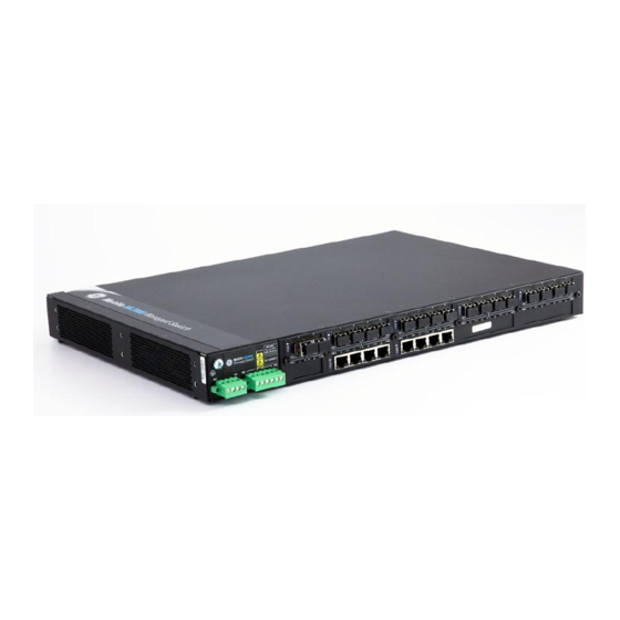
Overview 2.1.1 Introduction to the ML3000 The Multilink ML3000 Ethernet Switch provides rack-mount space efficiency and advanced port configurability for heavy duty industrial applications where maximum fiber port count and diversity are required. New advanced thermal design techniques (patent pending) enable the ML3000 to deliver high reliability and configurability even at extended operating temperatures. -
Page 46: Design Aspects
2.1.2 Design Aspects Designed for use in network traffic centers, the MultiLink ML3000 Ethernet Switch is easy to install and use. Addresses of attached nodes are automatically learned, maintained, and aged out, adapting the switching services to network changes. LEDs provide status information on each port. -
Page 47: Ml3000 Modules
• OFF (Half Duplex) for Copper port Power Indicator (Illuminated when power is supplied to the internal switch) Link indicators (Illuminated when Link is established to that port) FIGURE 2–1: LED Indicators MULTILINK ML3000 ETHERNET COMMUNICATIONS SWITCH – INSTRUCTION MANUAL 2–3... -
Page 48: Module A (100Mb) - Four Rj45 Ports (Use In Slots 3-10)
L/A LED to provide valid indications of operating conditions on that port. Using the Multilink ML3000 software, the user may disable auto-negotiation and fix the desired operation of each RJ-45 port. The user may select 10Mb or 100Mb speed and full- or half-duplex mode per-port as required. -
Page 49: Module K, Module M (100 Mb) - Four Singlemode Lc (Use In Slots 3-10)
(Link) with the remote device when lit and blinking (Activity), indicating packets being received. A module similar to Module H is also available with IEEE 1588v2 Timing Synchronization as Module T. MULTILINK ML3000 ETHERNET COMMUNICATIONS SWITCH – INSTRUCTION MANUAL 2–5... -
Page 50: Odule F, Modulee
The Module N four port module provides four 100 Mb open SFP ports, supporting distances up to 40 km. This module provides the same functions as Module G (see Section 2.2.3 for more details). 2–6 MULTILINK ML3000 ETHERNET COMMUNICATIONS SWITCH – INSTRUCTION MANUAL... -
Page 51: Moduleh (G B ) - Two Gigabit
AUTO mode for best fiber distance and performance. Each port has a Link/Activity (L/A) LED indicating proper connectivity (Link) with the remote device when lit and blinking (Activity), indicating packets being received. MULTILINK ML3000 ETHERNET COMMUNICATIONS SWITCH – INSTRUCTION MANUAL 2–7... -
Page 52: Features And Benefits
The ML3000 includes licensed software, allowing configuration of the ML3000 as a managed switch. All software information, including new releases and upgrades, can be accessed and download from the GE website at http://www.gedigitalenergy.com. 2–8 MULTILINK ML3000 ETHERNET COMMUNICATIONS SWITCH – INSTRUCTION MANUAL... -
Page 53: Redundant Power Supply
• 19” Rack-mounting: The standard rack mounting provides Ethernet ports and status LEDs in front, service connections (power input and management console) in the rear. “Reverse” rack mounting provides status LEDs in front and all cabling MULTILINK ML3000 ETHERNET COMMUNICATIONS SWITCH – INSTRUCTION MANUAL 2–9... - Page 54 • S-Ring and Link Loss Learn for economical high availability using ring topology: S-Ring, combined with the Link-Loss-Learn feature, provides reliable fast recovery of a fault in an economical ring topology, combining unmanaged and managed switches. 2–10 MULTILINK ML3000 ETHERNET COMMUNICATIONS SWITCH – INSTRUCTION MANUAL...
-
Page 55: Applications
2.4.1 Description The Multilink ML3000 Ethernet Switch offers high performance, modularity and availability. It provides the flexibility of 100 Mbps fiber, copper, and Gigabit (1000 Mb) ports, with industry-standard LAN management software. The ML3000 switches are easily used in a... -
Page 56: Ml3000 In A Redundant Ring Topology
Gigabit up-links to a central operations center for the vital database located in a separate secured building. The network will be manageable to provide easy, detectable, uninterrupted support through a viewable SNMP monitor. 2–12 MULTILINK ML3000 ETHERNET COMMUNICATIONS SWITCH – INSTRUCTION MANUAL... - Page 57 40 milliseconds) for cable breaks or similar network faults when set up in a ring topology. The Gigabit ports option boosts the bandwidth for high speed to support high traffic loads and minimize congestion. MULTILINK ML3000 ETHERNET COMMUNICATIONS SWITCH – INSTRUCTION MANUAL 2–13...
- Page 58 PRODUCT DESCRIPTION CHAPTER 2: PRODUCT DESCRIPTION 2–14 MULTILINK ML3000 ETHERNET COMMUNICATIONS SWITCH – INSTRUCTION MANUAL...
-
Page 59: Preparation
Verify that the equipment has a reliable and uncompromised earthing path. Esnure equipment is to be installed by service personnel in a restricted operation area. This chapter describes installation of the MultiLink ML3000 Ethernet Switch, as well as connection of the various Ethernet media types. 3.1.2 Locating the ML3000 For mounting instructions, refer to Mechanical Installation on page 3–6. - Page 60 When connecting the Ethernet cabling, there is no need to power down the unit. Individual cable segments can be connected or disconnected without concern for power-related problems or damage to the unit. 3–2 MULTILINK ML3000 ETHERNET COMMUNICATIONS SWITCH – INSTRUCTION MANUAL...
-
Page 61: Description
(assuming power is ON). If LINK is not lit after cable connection, the cause may be improper cable polarity. Swap the fiber cables at the module connector to remedy this situation. This product is fitted with Class I lasers. Note MULTILINK ML3000 ETHERNET COMMUNICATIONS SWITCH – INSTRUCTION MANUAL 3–3... -
Page 62: Connecting Sc- Type Fibero
100 m (328 ft.). Use high quality CAT. 5E cables (which work at both 100 and 1000 Mb) whenever possible Note to provide flexibility in a mixed-speed network. NOTE 3–4 MULTILINK ML3000 ETHERNET COMMUNICATIONS SWITCH – INSTRUCTION MANUAL... -
Page 63: Connecting Gigabit Media Using
3.2.6 Connecting Gigabit Media using GBICs The Gigabit ports accept industry-standard GBICs for user selection of the gigabit media type desired. A selection of fiber and copper GBICs are available. MULTILINK ML3000 ETHERNET COMMUNICATIONS SWITCH – INSTRUCTION MANUAL 3–5... -
Page 64: Mechanical Installation
3.3.1 Rack Mounting Installation of a MultiLink ML3000 Ethernet Switch in a 19-inch rack is a simple procedure. The units are 1 U (1.75") high. When properly installed, the front-mounted LED status indicators should be in plain view and easy to read. Rack-mount installation requires special 19-inch rack-mounted brackets and screws (included with the ML3000). -
Page 65: Electrical Installation
Pin 6 Pin 1 Pin 4 Pin 1 Pin 4: Ground 18 AWG minimum 14 AWG minimum Pin 5: (Negative)/Neutral N/- L/+ N/- L/+ Pin 6: (Positive)/Live [9 inch-pound maximum pin torque] MULTILINK ML3000 ETHERNET COMMUNICATIONS SWITCH – INSTRUCTION MANUAL 3–7... -
Page 66: Alarm Contacts
The switch’s software operation needs to be enabled and set to get the Alarm traps. For detailed information about the Software Alarm and software control of SNMP alarm traps, please reference the User Manual. 3–8 MULTILINK ML3000 ETHERNET COMMUNICATIONS SWITCH – INSTRUCTION MANUAL... -
Page 67: Dielectric Strength ( Hi - Pot ) T
The shorting link between the and safety ground must be removed prior to the dielectric strength test, as shown below, to protect the transient suppression circuitry of the power supply. FIGURE 3–2: Dielectric strength testing MULTILINK ML3000 ETHERNET COMMUNICATIONS SWITCH – INSTRUCTION MANUAL 3–9... - Page 68 INSTALLATION CHAPTER 3: INSTALLATION 3–10 MULTILINK ML3000 ETHERNET COMMUNICATIONS SWITCH – INSTRUCTION MANUAL...
-
Page 69: Functionality
4.1.1 Switching Functionality The MultiLink ML3000 provides switched connectivity at Ethernet wire-speed. The ML3000 supports10/100 Mbps for copper media and 10 or 100 Mb separate traffic domains for fiber ports to maximize bandwidth utilization and network performance. All ports can communicate to other ports in a ML3000, but local traffic on a port will not consume any of the bandwidth on any other port. -
Page 70: Status Leds
MNS software port settings and can check the port status of each port after the change. When Multilink ML3000 RJ-45 copper ports are set for auto-negotiation and are connected to another auto-negotiating device, there are 4 different speed and F/H modes possible depending on what the other device supports. -
Page 71: Flow Control
When operating in 100Mb half-duplex mode, cable distances and hop-counts may be limited within that collision domain. The Path Delay Value (PDV) bit-times must account for all devices and cable lengths within that domain. For Multilink ML3000 Fast Ethernet switched ports operating at 100Mb half-duplex, the bit time delay is 50BT. -
Page 72: Power Budget Calculations With
M, Z 100 Mb FX Single- 1310 9/125 32.5 1000 Mb SX Multi- 0.55+ 62.5/125 -9.5 10.5 (Gigabit) (0.22) 50/125 1000 Mb SX + Multi- 1310 62.5/125 -9.0 Extn. Dist. 50/125 4–4 MULTILINK ML3000 ETHERNET COMMUNICATIONS SWITCH – INSTRUCTION MANUAL... - Page 73 The worst-case OPB of the fiber link must be greater than the fiber cable's passive attenuation, where attenuation is the sum of cable loss, LED aging loss, insertion loss, and safety factor. MULTILINK ML3000 ETHERNET COMMUNICATIONS SWITCH – INSTRUCTION MANUAL 4–5...
-
Page 74: D Escription
However, if you are unsure of the procedures described in this section or if the ML3000 is not performing as expected, do not attempt to repair the unit; instead contact your supplier for assistance or contact GE Multilin. 4.2.2... -
Page 75: Ip Address And System Information
IP Address: 3.94.247.41 Subnet Mask: 255.255.252.0 Default Gateway: 3.94.244.1 ML3000> To verify the IP address using the EnerVista Secure Web Management software, Select the Administration > System menu item to view. MULTILINK ML3000 ETHERNET COMMUNICATIONS SWITCH – INSTRUCTION MANUAL 5–1... - Page 76 Edit the IP address information. Besides manually assigning IP addresses, there are other means to assign an IP address automatically. The two most common procedures are using DHCP and bootp. 5–2 MULTILINK ML3000 ETHERNET COMMUNICATIONS SWITCH – INSTRUCTION MANUAL...
-
Page 77: C Ommands
This is useful when a new switch is placed on a network and the IT policies are set to load a specific image which is supported and tested by IT personnel. MULTILINK ML3000 ETHERNET COMMUNICATIONS SWITCH – INSTRUCTION MANUAL 5–3... -
Page 78: E Xample
Select the Administration > System menu item. Click Edit. Alternatively, select items in the Administration > Set menu to individually modify the boot mode, date and time, log size, etc. 5–4 MULTILINK ML3000 ETHERNET COMMUNICATIONS SWITCH – INSTRUCTION MANUAL... -
Page 79: Using Telnet
The following example changes the telnet access. In this case, the enable command was repeated without any effect to the switch. ML3000# configure access ML3000(access)## telnet enable Access to Telnet already enabled ML3000(access)## exit ML3000# MULTILINK ML3000 ETHERNET COMMUNICATIONS SWITCH – INSTRUCTION MANUAL 5–5... - Page 80 The default port for telnet is 23. To start a telnet session through the EnerVista Secure Web Management software, Select the Administration > Telnet menu item. The default port for telnet is 23. 5–6 MULTILINK ML3000 ETHERNET COMMUNICATIONS SWITCH – INSTRUCTION MANUAL...
- Page 81 As well, if a outbound telnet session is started from the switch (through a telnet window) then other windows will not be able to execute a command until the telnet session is completed. MULTILINK ML3000 ETHERNET COMMUNICATIONS SWITCH – INSTRUCTION MANUAL 5–7...
-
Page 82: Setting Parameters
IP Address: 3.94.247.41 Subnet Mask: 255.255.252.0 Gateway Address: 3.94.244.1 CLI Mode: Manager System Name: ML3000 System Description: 25 Port Modular Ethernet Switch System Contact: multilin.tech@ge.com System Location: Markham, Ontario System ObjectId: 1.3.6.1.4.1.13248.12.7 ML3000# 5–8 MULTILINK ML3000 ETHERNET COMMUNICATIONS SWITCH – INSTRUCTION MANUAL... -
Page 83: E Xample
System UpTime: 7 Days 12 Hours 30 Mins 46 Secs ML3000# System variables can be changed. Below is a list of system variables which GE recommends changing. • : Using a unique name helps you to identify individual devices in a System Name network. -
Page 84: Date And Time
Simple Network Time Protocol (SNTP). To specify the SNTP server, one has to Set the IP parameters on the switch Define the SNTP parameters 5–10 MULTILINK ML3000 ETHERNET COMMUNICATIONS SWITCH – INSTRUCTION MANUAL... - Page 85 Configuration > SNTP menu item. The SNTP menu allows the time zone (hours from GMT) to be defined along with other appropriate parameters on setting the time and synchronizing clocks on network devices. MULTILINK ML3000 ETHERNET COMMUNICATIONS SWITCH – INSTRUCTION MANUAL 5–11...
- Page 86 You can use the IP address of these servers; however, please ensure the server can be reached by using the command. NOTE ping command can also be launched from the EnerVista software. ping 5–12 MULTILINK ML3000 ETHERNET COMMUNICATIONS SWITCH – INSTRUCTION MANUAL...
- Page 87 Internet. Ensure the IP parameters are configured for the switch and the device can be pinged by the switch. Once the server is added, it is listed with the other SNTP servers. MULTILINK ML3000 ETHERNET COMMUNICATIONS SWITCH – INSTRUCTION MANUAL 5–13...
-
Page 88: System Configuration
5.4.2 Config file Multilink ML3000 Firmware can use the ftp or tftp (or xmodem if using the CLI) to upload and download information to a server running the proper services. One useful capability provided is export of the CLI commands used to configure the switch. To do this, use Config Upload/Download. - Page 89 # test environment prior to use in a "live" production network. # All modifications are made at the User's own risk and are # subject to the limitations of the GE MultiLink software End User # License Agreement (EULA). Incorrect usage may result in # network shutdown.
- Page 90 CRC computed and stored in the file would not be matched. Should you want to edit, edit the System portion of the file only. GE Multilin, Inc. recommends editing the “script” file (see below) File names cannot have special characters such as *#!@$^&* space and control...
-
Page 91: Displaying Configuration
802.1x Settings igmp IGMP Settings smtp SMTP settings If the module name is not specified the whole configuration is displayed. ML3000# show config [HARDWARE] type= ML3000 slotB=8 Port TP Module ########################################################## MULTILINK ML3000 ETHERNET COMMUNICATIONS SWITCH – INSTRUCTION MANUAL 5–17... - Page 92 # System Manager - This area configures System related information. ########################################################## [SYSTEM] ***Edit below this line only**** system_name=Main system_contact=someone@joe.com system_location= Markham, Ontario boot_mode=manual system_ip=192.168.1.15 system_subnet=0.0.0.0 system_gateway=192.168.1.11 idle_timeout=10 telnet_access=enable snmp_access=enable web_access=enable --more— FIGURE 5–2: ’show config’ command output 5–18 MULTILINK ML3000 ETHERNET COMMUNICATIONS SWITCH – INSTRUCTION MANUAL...
- Page 93 # Network Management - This area configures the SNMPv3 agent. ########################################################## [SNMP] engineid=LE_v3Engine defreadcomm=public defwritecomm=private deftrapcomm=public authtrap=disable com2sec_count=0 group_count=0 view_count=1 view1_name=all view1_type=included view1_subtree=.1 view1_mask=ff --more— FIGURE 5–3: Displaying specific modules using the ‘show config’ command MULTILINK ML3000 ETHERNET COMMUNICATIONS SWITCH – INSTRUCTION MANUAL 5–19...
-
Page 94: Saving Configuration
Without a reboot, the ML3000 used the previous configuration. When reboot is selected, the user is prompted as follows: Reboot? ['Y' or 'N'] Select “Y”. The ML3000 will prompt: Save Current Configuration? Select “N”. 5–20 MULTILINK ML3000 ETHERNET COMMUNICATIONS SWITCH – INSTRUCTION MANUAL... - Page 95 With release 1.7 and higher, the configuration can be saved in the older format (binary Note object) or in a new format as an ASCII file. The new format is recommended by GE Multilin. Use the old format only if there are multiple MultiLink switches on the network running different versions of software.
-
Page 96: Script File
Firmware. The script file does not have a check sum at the end and is used for configuring a large number of switches easily. As with any configuration file that is uploaded, GE Multilin, Inc. recommends that modifications of this file and the commands should be verified by the user in a test environment prior to use in a "live"... -
Page 97: Saving And Loading - Enervista Software
In the above example, note that all the commands are CLI commands. This script provides an insight into the configuration of GE MultiLink switches settings. GE Multilin, Inc. recommends that modifications of this file and the commands should be verified by the User in a test environment prior to use in a "live"... - Page 98 The software will ask again if the changes need to be saved or ignored. If the changes need to be ignored, click on Cancel and reboot the switch. If the changes need to be saved, click on OK. 5–24 MULTILINK ML3000 ETHERNET COMMUNICATIONS SWITCH – INSTRUCTION MANUAL...
-
Page 99: Host Names
Instead of typing in IP addresses of commonly reached hosts, the ML3000 allows hosts to be created with the necessary host names, IP addresses, user names, and passwords. Use the Configuration > Access > Host menu to create host entries as shown below. MULTILINK ML3000 ETHERNET COMMUNICATIONS SWITCH – INSTRUCTION MANUAL 5–25... - Page 100 IP ADDRESSING CHAPTER 5: IP ADDRESSING To add a host, click the Add button. Fill in all the fields below to create the necessary host entries. 5–26 MULTILINK ML3000 ETHERNET COMMUNICATIONS SWITCH – INSTRUCTION MANUAL...
-
Page 101: Erasing Configuration
Administration tab by selecting kill config. User also has the option to save one module from defaulting back to factory defaults by Note checking the module box before issuing kill Config command. NOTE MULTILINK ML3000 ETHERNET COMMUNICATIONS SWITCH – INSTRUCTION MANUAL 5–27... - Page 102 When the OK button is pressed the Switch will issue the following warning messages; and reboot the switch for it to revert back to the factory default settings with the exceptions of modules opted not to be defaulted. 5–28 MULTILINK ML3000 ETHERNET COMMUNICATIONS SWITCH – INSTRUCTION MANUAL...
- Page 103 The kill Config command will default all the Switch settings back to factory defaults, while the kill config save=module will default all with the exception of module selected. Available modules are: system, user, acces, port, vlan, ps, mirror, lacp, slp, and igmp. MULTILINK ML3000 ETHERNET COMMUNICATIONS SWITCH – INSTRUCTION MANUAL 5–29...
- Page 104 Do you want to erase the configuration? ['Y' or 'N'] Y Successfully erased configuration...Please reboot. Once the configuration is erased, please reboot the switch for the changes to take effect. 5–30 MULTILINK ML3000 ETHERNET COMMUNICATIONS SWITCH – INSTRUCTION MANUAL...
-
Page 105: Ipv6
CHAPTER 5: IP ADDRESSING IP ADDRESSING IPv6 This section explains how to access the GE MultiLink switches using IPv6 instead of IPv4 addressing. IPv6 provides a much larger address space and its use is often required. Assumptions It is assumed here that the user is familiar with IP addressing schemes and has other supplemental material on IPv6, configuration, routing, setup and other items related to IPv6. -
Page 106: Ipv6 Addressing
The only exception is the ‘ping’ command where there is a special command for IPv6. That commands is ‘ping6’ and the syntax is as 5–32 MULTILINK ML3000 ETHERNET COMMUNICATIONS SWITCH – INSTRUCTION MANUAL... - Page 107 Besides, if the end station supports IPv6 addressing (as most Linux and Windows systems do), one can access the switch using the IPv6 addressing as shown in the example below http://fe80::220:6ff:fe25:ed80 MULTILINK ML3000 ETHERNET COMMUNICATIONS SWITCH – INSTRUCTION MANUAL 5–33...
-
Page 108: List Of Commands In This Chapter
Syntax ping6 <IPv6 address> - pings an IPv6 station Syntax show ipv6 - displays the IPv6 information Syntax ftp <IPv6 address> - ftp to an IPv6 station Syntax telnet <IPv6 address> - telnet to an IPv6 station. 5–34 MULTILINK ML3000 ETHERNET COMMUNICATIONS SWITCH – INSTRUCTION MANUAL... -
Page 109: Securing Access
MAC address as well as IP address. NOTE 6.1.2 Passwords The GE MultiLink family of switches have a factory default password for the manager as well as the operator account. Passwords can be changed from the user ID by using the command. set password... -
Page 110: Port Security Feature
Once that is decided, the next few decisions are: Who are the authorized and unauthorized users? What action should be taken against authorized as well as unauthorized users? How are the users identified as authorized or unauthorized? 6–2 MULTILINK ML3000 ETHERNET COMMUNICATIONS SWITCH – INSTRUCTION MANUAL... -
Page 111: Configuring Port Security Through The Command Line Interface
• - specifies the designated action to take in case of a non action port authorized access • - port security - allows port security to be enable or disabled MULTILINK ML3000 ETHERNET COMMUNICATIONS SWITCH – INSTRUCTION MANUAL 6–3... -
Page 112: Allowing Mac Addresses
Use the following commands: #port-security (port-security)##ps enable (port-security)##allow mac=<address,list,range> port=<num,list,range> (port-security)##action port=<num,list,range>drop All the above commands have to be configured in this sequence, otherwise the port will Note remain insecure. NOTE 6–4 MULTILINK ML3000 ETHERNET COMMUNICATIONS SWITCH – INSTRUCTION MANUAL... - Page 113 11 ENABLE NONE NONE ENABLE 0 Not Configured 12 ENABLE NONE NONE DISABLE 0 Not Configured 13 ENABLE NONE NONE DISABLE 0 Not Configured 14 ENABLE NONE NONE DISABLE 0 Not Configured MULTILINK ML3000 ETHERNET COMMUNICATIONS SWITCH – INSTRUCTION MANUAL 6–5...
- Page 114 Example 6-4: Removing MAC addresses from specific ports ML3000(port-security)## remove mac=00:c1:00:7f:ec:00 port=13 Specified MAC address(es) removedfrom selected port(s) ML3000(port-security)## show port-security port=13 PORT STATE SIGNAL ACTION LEARN COUNT MAC ADDRESS ---- ----- ------ ------ ----- ----- ----------- 6–6 MULTILINK ML3000 ETHERNET COMMUNICATIONS SWITCH – INSTRUCTION MANUAL...
- Page 115 (Optional step) Set the notification to notify the management station on security breach attempts (use the command signal port make a log entry or send a trap). MULTILINK ML3000 ETHERNET COMMUNICATIONS SWITCH – INSTRUCTION MANUAL 6–7...
-
Page 116: Security Logs
PORT STATE SIGNAL ACTION LEARN COUNT MAC ADDRESS ---- ----- ------ ------ ----- ----- ----------- 11 ENABLE NONE DROP ENABLE 0 00:c1:00:7f:ec:00 ML3000(port-security)## signal port=11 logandtrap Port security Signal type set to Log and Trap on selected port(s) 6–8 MULTILINK ML3000 ETHERNET COMMUNICATIONS SWITCH – INSTRUCTION MANUAL... - Page 117 ML3000# clear log informational Clear Logged Events? ['Y' or 'N'] ML3000# show log S Date Time Log Description - ---- ---- --------------- A 12-17-2004 12:05:52 P.M PS:INTRUDER 00:e0:29:6c:a4: fd@port11, packet dropped MULTILINK ML3000 ETHERNET COMMUNICATIONS SWITCH – INSTRUCTION MANUAL 6–9...
-
Page 118: Authorized Managers
(information, severity level 1) indicates routine events. • (activity, severity level 2) indicates the activity on the switch. • (debug, severity level 3) is reserved for GE Multilin internal diagnostic information • (critical, severity level 4) indicates that a severe switch error has occurred. •... - Page 119 Service(s) allowed for specified address ML3000(access)## remove ip=3.94.245.15 mask=255.255.255.255 Access entry removed ML3000(access)## exit ML3000# show ip-access ============================================================ IP Address | Mask | Telnet | Web | SNMP | ============================================================ 3.94.245.10 255.255.255.0 ALLOWED DENIED DENIED MULTILINK ML3000 ETHERNET COMMUNICATIONS SWITCH – INSTRUCTION MANUAL 6–11...
-
Page 120: Configuring Port Security With Enervista Software
MAC addresses and specify individual MAC addresses. To edit each port, click on the edit icon ( To enable or disable port security, use the Status drop down menu as shown below. 6–12 MULTILINK ML3000 ETHERNET COMMUNICATIONS SWITCH – INSTRUCTION MANUAL... - Page 121 To delete a MAC address, click on the delete icon ( To add a MAC address, click on the Add button and fill in the MAC address in the MAC address window. MULTILINK ML3000 ETHERNET COMMUNICATIONS SWITCH – INSTRUCTION MANUAL 6–13...
-
Page 122: Logs
All events occurring on the Managed MultiLink switch are logged. The events can be informational (e.g. login, STP synchronization etc.), debugging logs (for debugging network and other values), critical (critical events), activity (traffic activity) and fatal events (such as 6–14 MULTILINK ML3000 ETHERNET COMMUNICATIONS SWITCH – INSTRUCTION MANUAL... - Page 123 Severity has one of the following values, and depending on the severity type, is assigned a severity level. • (information, severity level 1) indicates routine events. • (activity, severity level 2) indicates the activity on the switch. MULTILINK ML3000 ETHERNET COMMUNICATIONS SWITCH – INSTRUCTION MANUAL 6–15...
-
Page 124: Authorized Managers
ACCESS CONSIDERATIONS CHAPTER 6: ACCESS CONSIDERATIONS • (debug, severity level 3) is reserved for GE Multilin internal diagnostic information • (critical, severity level 4) indicates that a severe switch error has occurred. • (fatal, severity level 5) indicates that a service has behaved unexpectedly. - Page 125 CHAPTER 6: ACCESS CONSIDERATIONS ACCESS CONSIDERATIONS MULTILINK ML3000 ETHERNET COMMUNICATIONS SWITCH – INSTRUCTION MANUAL 6–17...
- Page 126 ACCESS CONSIDERATIONS CHAPTER 6: ACCESS CONSIDERATIONS 6–18 MULTILINK ML3000 ETHERNET COMMUNICATIONS SWITCH – INSTRUCTION MANUAL...
-
Page 127: Introduction To 802.1X
The authenticator is responsible for communication with the supplicant and for submitting the information received from the supplicant to a suitable authentication server. This allows the verification of user MULTILINK ML3000 ETHERNET COMMUNICATIONS SWITCH – INSTRUCTION MANUAL 7–1... - Page 128 10. If the supplicant does not have the necessary credentials, a RADIUS-Access- Deny packet is relayed to the supplicant as an EAP-Failure frame. The access to the network continues to be blocked. 7–2 MULTILINK ML3000 ETHERNET COMMUNICATIONS SWITCH – INSTRUCTION MANUAL...
- Page 129 • Relays MD5 challenge (although not limited to) authentication protocol to RADIUS server • Limits the authentication of a single host per port • The MultiLink switch provides the IEEE 802.1x MIB for SNMP management MULTILINK ML3000 ETHERNET COMMUNICATIONS SWITCH – INSTRUCTION MANUAL 7–3...
-
Page 130: Configuring 802.1X Through The Command Line Interface
This is the time in seconds the authenticator waits to transmit another request for identification from the supplicant. The default value is 30 and values range from 1 to 65535 seconds 7–4 MULTILINK ML3000 ETHERNET COMMUNICATIONS SWITCH – INSTRUCTION MANUAL... - Page 131 3600 seconds (1 hour), and values range from 10 to 86400 seconds. command displays 802.1x related statistics. show-stats show-stats port=<num> command manually initiates a re-authentication of supplicant. trigger-reauth trigger-reauth port=<num|list|range> MULTILINK ML3000 ETHERNET COMMUNICATIONS SWITCH – INSTRUCTION MANUAL 7–5...
-
Page 132: Example
15 Enabled Auto Deasserted Unauthorized 16 Enabled Auto Deasserted Unauthorized -- Port not available ML3000(auth)## show auth config 802.1X Authenticator Configuration ================================== Status: Enabled RADIUS Authentication Server ================================== IP Address: 3.204.240.1 7–6 MULTILINK ML3000 ETHERNET COMMUNICATIONS SWITCH – INSTRUCTION MANUAL... - Page 133 120 seconds. These values can be changed on all ports depending on devices being authenticated. (continued on following page) MULTILINK ML3000 ETHERNET COMMUNICATIONS SWITCH – INSTRUCTION MANUAL 7–7...
- Page 134 : 0 authAuthEapStartsWhileAuthenticating : 1 authAuthEapLogoffWhileAuthenticating : 0 authAuthReauthsWhileAuthenticated authAuthEapStartsWhileAuthenticated : 0 authAuthEapLogoffWhileAuthenticated : 0 backendResponses backendAccessChallenges backendOtherRequestsToSupplicant backendNonNakResponsesFromSupplicant : 2 backendAuthSuccesses backendAuthFails ML3000(auth)## trigger-reauth port=3 Successfully triggered re-authentication ML3000(auth)## 7–8 MULTILINK ML3000 ETHERNET COMMUNICATIONS SWITCH – INSTRUCTION MANUAL...
-
Page 135: Configuring 802.1X With Enervista Secure Web Management Software
The following window shows the configuration of a RADIUS Server. Initially, the RADIUS Services are disabled and the server IP address is set to 0.0.0.0. Edit the server IP and secret to add a RADIUS server. MULTILINK ML3000 ETHERNET COMMUNICATIONS SWITCH – INSTRUCTION MANUAL 7–9... - Page 136 Ensure that the port which has the RADIUS server is force authorized and asserted. For other ports (user ports), it is best to leave the Control on auto and Initialize on de-asserted. 7–10 MULTILINK ML3000 ETHERNET COMMUNICATIONS SWITCH – INSTRUCTION MANUAL...
- Page 137 0 to 65535 seconds, with a default of 60. The Max Reauth column shows the permitted reauthentication attempts before the port becomes unauthorized. Values are integers ranging from 0 to 10, with a default of 2. MULTILINK ML3000 ETHERNET COMMUNICATIONS SWITCH – INSTRUCTION MANUAL 7–11...
- Page 138 The Max Request column represents the maximum times the authenticator retransmits an EAP request packet to the supplicant before it times out. Values are integers ranging from 1 to 10, with a default of 2. 7–12 MULTILINK ML3000 ETHERNET COMMUNICATIONS SWITCH – INSTRUCTION MANUAL...
- Page 139 After all the port characteristics are enabled, Do not forget to save the configuration using the Save ( ) icon and enabling RADIUS from the Configuration > Radius > Server menu. MULTILINK ML3000 ETHERNET COMMUNICATIONS SWITCH – INSTRUCTION MANUAL 7–13...
- Page 140 ACCESS USING RADIUS CHAPTER 7: ACCESS USING RADIUS 7–14 MULTILINK ML3000 ETHERNET COMMUNICATIONS SWITCH – INSTRUCTION MANUAL...
-
Page 141: Introduction To Tacacs
Clients connect to this port to send authentication and authorization packets. There can be more than one TACACS+ server on the network. The MultiLink Switch Software supports a maximum of five TACACS+ servers. MULTILINK ML3000 ETHERNET COMMUNICATIONS SWITCH – INSTRUCTION MANUAL 8–1... -
Page 142: Tacacs+ Flow
EtherReal or others. Packet data is hashed and shared using MD5 and secret string defined between the MultiLink switches and the TACACS+ server. 8–2 MULTILINK ML3000 ETHERNET COMMUNICATIONS SWITCH – INSTRUCTION MANUAL... - Page 143 • Flags: This field contains various flags in the form of bitmaps. The flag values signify whether the packet is encrypted. • Session ID: The ID for this TACACS+ session. • Length: The total length of the TACACS+ packet body (not including the header). MULTILINK ML3000 ETHERNET COMMUNICATIONS SWITCH – INSTRUCTION MANUAL 8–3...
-
Page 144: Configuring Tacacs+ Through The Command Line Interface
The argument requires the secret shared key string must be supplied when encryption is enabled. 8.2.2 Example The example below illustrates how to configure TACACS+. 8–4 MULTILINK ML3000 ETHERNET COMMUNICATIONS SWITCH – INSTRUCTION MANUAL... - Page 145 CHAPTER 8: ACCESS USING TACACS+ ACCESS USING TACACS+ MULTILINK ML3000 ETHERNET COMMUNICATIONS SWITCH – INSTRUCTION MANUAL 8–5...
-
Page 146: Configuring Tacacs+ With Enervista Secure Web Management Software
To add a server, click on the Add button as shown below. Note that the TCP port field can be left blank – port 49 is used as a default port. Up to five TACACS+ servers can be defined. 8–6 MULTILINK ML3000 ETHERNET COMMUNICATIONS SWITCH – INSTRUCTION MANUAL... - Page 147 CHAPTER 8: ACCESS USING TACACS+ ACCESS USING TACACS+ After the configuration is completed, Save the settings. Enable the TACACS+ services by using the Status drop down menu. MULTILINK ML3000 ETHERNET COMMUNICATIONS SWITCH – INSTRUCTION MANUAL 8–7...
- Page 148 ACCESS USING TACACS+ CHAPTER 8: ACCESS USING TACACS+ 8–8 MULTILINK ML3000 ETHERNET COMMUNICATIONS SWITCH – INSTRUCTION MANUAL...
-
Page 149: Port Mirroring
9.1.1 Description This section explains how individual characteristics of a port on a GE MultiLink switch is configured. For monitoring a specific port, the traffic on a port can be mirrored on another port and viewed by protocol analyzers. Other setup includes automatically setting up broadcast storm prevention thresholds. -
Page 150: Port Mirroring Using The Command Line Interface
Sniffer Port: 13 Monitor Port: 11 Mirroring State: enabled ML3000# Once port monitoring is completed, GE strongly recommends that the port mirroring be disabled using the command for security reasons. prtmr disable Only one port can be set to port mirror at a time. -
Page 151: Port Setup
PORT MIRRORING & SETUP Port Setup 9.3.1 Commands Each port on the GE MultiLink family of switches can be setup specific port characteristics. The commands for setting the port characteristics are shown below. command enters the device configuration mode: device... - Page 152 10Tx DOWN 10 No E 13 B5 100Tx UP 100 No E 14 B6 10Tx DOWN 10 No E 15 B7 10Tx DOWN 10 No E 16 B8 10Tx DOWN 10 No E 9–4 MULTILINK ML3000 ETHERNET COMMUNICATIONS SWITCH – INSTRUCTION MANUAL...
-
Page 153: Flow Control
Alternately, QoS and other techniques are widely used today. In the example below, the MultiLink family of switches are setup with flow control and back pressure. MULTILINK ML3000 ETHERNET COMMUNICATIONS SWITCH – INSTRUCTION MANUAL 9–5... - Page 154 XOffLimit : 6 ML3000(device)## flowcontrol xonlimit=10 xofflimit=15 XOn Limit set successfully XOff Limit set successfully ML3000(device)## show flowcontrol XOnLimit : 10 XOffLimit : 15 ML3000(device)## show backpressure Rx Buffer Threshold : 28 9–6 MULTILINK ML3000 ETHERNET COMMUNICATIONS SWITCH – INSTRUCTION MANUAL...
- Page 155 : None Port Security : Enable Port Flow Control : Disable Port Back Pressure : Disable Port Link Loss Alert : Enabled ML3000(device)## setport port=11 flow=enable bp=enable (continued on next page) MULTILINK ML3000 ETHERNET COMMUNICATIONS SWITCH – INSTRUCTION MANUAL 9–7...
-
Page 156: Broadcast Storms
The storm is determined to be over when a one-second period elapses with no broadcast packets received. 9–8 MULTILINK ML3000 ETHERNET COMMUNICATIONS SWITCH – INSTRUCTION MANUAL... - Page 157 In Example 9-3, the broadcast protection is turned on. The threshold for port 11 is then set to a lower value of 3500 broadcast frames/second. MULTILINK ML3000 ETHERNET COMMUNICATIONS SWITCH – INSTRUCTION MANUAL 9–9...
-
Page 158: Link Loss Alert
9.3.5 Link Loss Alert The GE Multilin Universal Relay (UR) family and the F650 family of relays have redundant Ethernet ports that allow for automatic switching to their secondary ports when they detect the primary path is broken. The MultiLink switches can compensate for situations where only the switch receiver fiber cable is broken. - Page 159 Port Duplex Mode : half-duplex Port Auto-negotiation State : Enable Port STP State : NO STP Port GVRP State : No GVRP Port Priority Type : None Port Security : Enable MULTILINK ML3000 ETHERNET COMMUNICATIONS SWITCH – INSTRUCTION MANUAL 9–11...
-
Page 160: Port Mirroring Using Enervista Secure Web Management Software
To enable port mirroring as well as setting up the ports to be “sniffed”, Select the Configuration > Port > Mirroring menu item. Set the sniffer port and the port on which the traffic is reflected. 9–12 MULTILINK ML3000 ETHERNET COMMUNICATIONS SWITCH – INSTRUCTION MANUAL... -
Page 161: Port Setup
Make sure the Mirror Status is also set to enabled for mirroring: For security reasons, GE Multilin recommends that the port mirroring be disabled using the Edit button and setting the Mirror Status to off once port monitoring is completed. - Page 162 • Port Name assigns a specific name to the port. This name is a designated name for the port and can be a server name, user name or any other name. • Admin Status indicates whether the port can be administered remotely. 9–14 MULTILINK ML3000 ETHERNET COMMUNICATIONS SWITCH – INSTRUCTION MANUAL...
- Page 163 • Auto: The port operates at 1000FDx and auto-negotiates flow control with the device connected to the port To change the port speed on a transceiver port, the switch must be rebooted MULTILINK ML3000 ETHERNET COMMUNICATIONS SWITCH – INSTRUCTION MANUAL 9–15...
-
Page 164: Broadcast Storms
9.4.3 Broadcast Storms One of the best features of the GE MultiLink switch is its ability to keep broadcast storms from spreading throughout a network. Network storms (or broadcast storms) are characterized by an excessive number of broadcast packets being sent over the network. - Page 165 After changes are made, do not forget to save the changes using the save icon ( If the switch is rebooted before the changes are made, the changes will be lost. MULTILINK ML3000 ETHERNET COMMUNICATIONS SWITCH – INSTRUCTION MANUAL 9–17...
- Page 166 PORT MIRRORING & SETUP CHAPTER 9: PORT MIRRORING & SETUP 9–18 MULTILINK ML3000 ETHERNET COMMUNICATIONS SWITCH – INSTRUCTION MANUAL...
-
Page 167: Vlan Description
The following figure illustrates a VLAN as two separate broadcast domains. The top part of the figure shows two “traditional” Ethernet segments. Up to 32 VLANs can be defined per switch. FIGURE 10–1: VLAN as two separate broadcast domains MULTILINK ML3000 ETHERNET COMMUNICATIONS SWITCH – INSTRUCTION MANUAL 10–1... - Page 168 VLANs easily and provides a cost effective solution if there are may VLANs defined. As shown below, routing between different VLANs is performed using a router or a Layer 3 switch (L3-switch) FIGURE 10–3: VLAN routing 10–2 MULTILINK ML3000 ETHERNET COMMUNICATIONS SWITCH – INSTRUCTION MANUAL...
-
Page 169: Tag Vlan Vs. Port Vlan
It is recommended to use IEEE 802.1q tagged based VLANs over port based VLANs because of there multi-vendor interoperability and capability of carrying the isolated tagged VLAN information when more than one switch is involved. MULTILINK ML3000 ETHERNET COMMUNICATIONS SWITCH – INSTRUCTION MANUAL 10–3... -
Page 170: Configuring Port Vlans Through The Command Line Interface
VLANs is needed however the broadcasts and multicasts are isolated to the specific VLAN. GE recommends using the set-port command for setting the port based VLAN as well. The port-based VLAN feature supports a maximum of 1 VLAN per port. Any pre-existing VLAN tags on traffic coming into the switch on a port-based VLAN port, will be removed. - Page 171 Saving current configuration... Configuration saved To move Management Control on any VLAN: add id=<vlan Id> [name=<vlan name>] port=<number|list|range> [Forbid=<number|list|range>][<mgt|nomgt>] To enable or disable Management Control on any VLAN: edit id=<vlan Id>[name=<vlan name>][port=<number|list|range>[<mgt|nomgt>] MULTILINK ML3000 ETHERNET COMMUNICATIONS SWITCH – INSTRUCTION MANUAL 10–5...
-
Page 172: Configuring Port Vlans With Enervista Secure Web Management Software
To eliminate the changes, reboot the switch without saving the changes. NOTE For VLAN configuration use Configuration > VLAN menu items as shown below. The Port VLANs are active by default. 10–6 MULTILINK ML3000 ETHERNET COMMUNICATIONS SWITCH – INSTRUCTION MANUAL... - Page 173 CHAPTER 10: VLAN VLAN The currently assigned Port VLANs are displayed as follows: Select the Configuration > VLAN > Port-Based menu item. MULTILINK ML3000 ETHERNET COMMUNICATIONS SWITCH – INSTRUCTION MANUAL 10–7...
- Page 174 VLAN with VID=40 and VLAN name = Support. Add the ports. Define the VLAN. Click OK. After adding the VLAN, the VLAN is not active. Activating the VLAN has to be done manually. 10–8 MULTILINK ML3000 ETHERNET COMMUNICATIONS SWITCH – INSTRUCTION MANUAL...
- Page 175 After activation, note that ports 13 to 16 belong to the new VLAN. The VLAN membership of the ports assigned to VLAN 40 now indicates that they are only members of VLAN 40. The default VLAN membership has been terminated on VLAN activation. MULTILINK ML3000 ETHERNET COMMUNICATIONS SWITCH – INSTRUCTION MANUAL 10–9...
-
Page 176: Configuring Tag Vlans Through The Command Line Interface
MultiLink Switch Software version 1.6.1. For legacy purposes, these NOTE commands will still work with release 1.6.1 (and will print a message on the screen indicating the commands are deprecated), however, GE strongly recommends avoiding these commands and using the command instead. -
Page 177: Example
Tag VLAN support VLAN ids from 1 to 4096. VLAN ids more than 2048 are reserved for specific purposes and it is recommended they not be used. MULTILINK ML3000 ETHERNET COMMUNICATIONS SWITCH – INSTRUCTION MANUAL 10–11... - Page 178 16 | DOWN ML3000(port-vlan)## stop vlan=all All active VLAN's stopped. ML3000(port-vlan)## exit ML3000# set vlan type=tag VLAN set to Tag-based. ML3000# show active-vlan Tag VLAN is currently active. (continued on next page) 10–12 MULTILINK ML3000 ETHERNET COMMUNICATIONS SWITCH – INSTRUCTION MANUAL...
- Page 179 ERROR: Duplicate Vlan Id ML3000(tag-vlan)## add id=30 name=marketing port=14-16 Tag based vlan Added Successfully. VLAN ID : 30 VLAN Name : marketing Ports : 14-16 (continued on next page) MULTILINK ML3000 ETHERNET COMMUNICATIONS SWITCH – INSTRUCTION MANUAL 10–13...
- Page 180 PORT | MODE | STATUS ============================== 14 | UNTAGGED | DOWN 15 | UNTAGGED | DOWN 16 | UNTAGGED | DOWN ML3000(tag-vlan)## start vlan=all All pending VLAN's started. (continued on next page) 10–14 MULTILINK ML3000 ETHERNET COMMUNICATIONS SWITCH – INSTRUCTION MANUAL...
- Page 181 14 | UNTAGGED | DOWN 15 | UNTAGGED | DOWN 16 | UNTAGGED | DOWN VLAN ID : 30 Name : marketing Status : Active ============================== PORT | MODE | STATUS ============================== MULTILINK ML3000 ETHERNET COMMUNICATIONS SWITCH – INSTRUCTION MANUAL 10–15...
- Page 182 14 | TAGGED | DOWN 15 | TAGGED | DOWN 16 | TAGGED | DOWN VLAN ID : 30 Name : marketing Status : Active ============================== PORT | MODE | STATUS ============================== 10–16 MULTILINK ML3000 ETHERNET COMMUNICATIONS SWITCH – INSTRUCTION MANUAL...
-
Page 183: Configuring Tag Vlans With Enervista Secure Web Management Software
When multiple switches are on a network, the VLAN information needs to be propagated on to other switches. In such situations, it is best to use tag based VLANs. On the MultiLink ML3000 Ethernet Switch, the port VLAN type is set to none. To use Tag VLANs, first enable Tag VLANs. - Page 184 • VLAN 1, All ports - default VLAN • VLAN 10, Engineering VLAN - ports 13, 14 • VLAN 20, Support VLAN - ports 13, 14, 15 (note that port 13 belongs to VLAN 10, 20) 10–18 MULTILINK ML3000 ETHERNET COMMUNICATIONS SWITCH – INSTRUCTION MANUAL...
- Page 185 VLAN 20, 30) After adding the ports and defining the VLAN, click OK. Click on Port Settings in the Configuration >VLAN >Tag-Based >Settings menu and enable the tagging for each port. MULTILINK ML3000 ETHERNET COMMUNICATIONS SWITCH – INSTRUCTION MANUAL 10–19...
- Page 186 After all the ports are tagged, the tagged column should change to “Yes” for all VLANs To check the status of the tagging, Select the Configuration > VLAN > Tag-Based > Tagging menu. 10–20 MULTILINK ML3000 ETHERNET COMMUNICATIONS SWITCH – INSTRUCTION MANUAL...
- Page 187 In the example below, we will take port 15 and assign it to leave VLAN 30. After the action is completed, note that port 15 will belong to VLAN 1 only. MULTILINK ML3000 ETHERNET COMMUNICATIONS SWITCH – INSTRUCTION MANUAL 10–21...
- Page 188 To enable the filter capability for each port, use the Configuration >VLAN >Tag-Based > Settings > Port Settings menu as shown below. Use the Configuration >VLAN >Tag-Based > Filter menu to view the filter information for the ports. 10–22 MULTILINK ML3000 ETHERNET COMMUNICATIONS SWITCH – INSTRUCTION MANUAL...
-
Page 189: Overview
The Generic Attribute Registration Protocol (GARP) and VLAN registration over GARP is called GVRP. GVRP is defined in the IEEE 802.1q and GARP in the IEEE 802.1p standards. To utilize the capabilities of GVRP, GE Multilin recommends that the user become familiar with the concepts and capabilities of IEEE 802.1q. -
Page 190: Gvrp Operations
There must be one common VLAN (that is, one common VID) connecting all of the GVRP- Note aware devices in the network to carry GVRP packets. GE Multilin recommends the default VLAN (DEFAULT_VLAN; VID = 1), which is automatically enabled and configured as NOTE untagged on every port of the MultiLink family of switches. - Page 191 VLANs • Send VLAN advertisements, but ignore advertisements received from other ports • Avoid GVRP participation by not sending advertisements and dropping any advertisements received from other devices MULTILINK ML3000 ETHERNET COMMUNICATIONS SWITCH – INSTRUCTION MANUAL 11–3...
- Page 192 VID advertised VLAN Disable Ignore GVRP and drop all Ignore GVRP and Do not allow the GVRP advertisements drop all GVRP VLAN on this port advertisements 11–4 MULTILINK ML3000 ETHERNET COMMUNICATIONS SWITCH – INSTRUCTION MANUAL...
- Page 193 Auto, and Forbid options are configured in the VLAN context. Since dynamic VLANs operate as tagged VLANs, and it is possible that a tagged port on one device may not communicate with an untagged port on another device, GE Multilin recommends that you use tagged VLANs for the static VLANs.
-
Page 194: Configuring Gvrp Through The Command Line Interface
Similarly, the switch advertises its static VLANs to other GVRP-aware devices. A GVRP-enabled switch does not advertise any GVRP-learned VLANs out of the port(s) on which it originally learned of those VLANs. 11–6 MULTILINK ML3000 ETHERNET COMMUNICATIONS SWITCH – INSTRUCTION MANUAL... - Page 195 | Default VLAN | Static | Active | Blue | Static | Active | dyn10 | Static | Active ML3000(gvrp)## set-forbid vlan=2 forbid=11-15 ML3000(gvrp)## show-forbid ============================================ VLAN ID | FORBIDDEN PORTS ============================================ | None MULTILINK ML3000 ETHERNET COMMUNICATIONS SWITCH – INSTRUCTION MANUAL 11–7...
-
Page 196: Configuring Gvrp With Enervista Secure Web Management Software
Auto, and Forbid options are configured in the VLAN context. Since dynamic VLANs operate as tagged VLANs, and it is possible that a tagged port on one device may not communicate with an untagged port on another device, GE Multilin recommends that you use tagged VLANs for the static VLANs. -
Page 197: Features And Operation
Thus, if an active path fails, STP automatically activates (unblocks) an available backup to serve as the new active path for as long as the original active path is down. MULTILINK ML3000 ETHERNET COMMUNICATIONS SWITCH – INSTRUCTION MANUAL 12–1... - Page 198 Bridge maximum age 20 seconds Hello time 2 seconds Forward delay 15 seconds Reconfiguring per-port STP path cost Priority 32768 Mode Normal Monitoring of STP Not available Root Port Not set 12–2 MULTILINK ML3000 ETHERNET COMMUNICATIONS SWITCH – INSTRUCTION MANUAL...
-
Page 199: Configuring Stp
When STP is not enabled, the switch designates itself as the root switch. • Designated Root Priority: Shows the designated root bridge's priority. The default value is 32768. MULTILINK ML3000 ETHERNET COMMUNICATIONS SWITCH – INSTRUCTION MANUAL 12–3... - Page 200 Disabled 80:00:00:20:06:25:ed:80 80:0a TP(10/100) 128 Disabled 80:00:00:20:06:25:ed:80 80:0b TP(10/100) 128 Disabled 80:00:00:20:06:25:ed:80 80:0c TP(10/100) 128 Disabled 80:00:00:20:06:25:ed:80 80:0d TP(10/100) 128 Disabled 80:00:00:20:06:25:ed:80 80:0e TP(10/100) 128 Disabled 80:00:00:20:06:25:ed:80 80:0f TP(10/100) 128 Disabled 80:00:00:20:06:25:ed:80 80:10 12–4 MULTILINK ML3000 ETHERNET COMMUNICATIONS SWITCH – INSTRUCTION MANUAL...
- Page 201 STP is currently active. show active-stp show active-stp Incorrect STP settings can adversely affect network performance. GE recommends starting Note with the default STP settings. Changing the settings requires a detailed understanding of STP. For more information on STP, please refer to the IEEE 802.1d standard.
- Page 202 -------------------------------------------------------------------------------------- TP(10/100) 128 Forwarding 80:00:00:20:06:25:ed:80 80:09 TP(10/100) 128 Disabled 80:00:00:20:06:25:ed:80 80:0a TP(10/100) 128 Disabled 80:00:00:20:06:25:ed:80 80:0b TP(10/100) 128 Disabled 80:00:00:20:06:25:ed:80 80:0c TP(10/100) 128 Forwarding 80:00:00:20:06:25:ed:80 80:0d TP(10/100) 128 Disabled 80:00:00:20:06:25:ed:80 80:0e 12–6 MULTILINK ML3000 ETHERNET COMMUNICATIONS SWITCH – INSTRUCTION MANUAL...
- Page 203 STP information is allowed by the switch before the switch discards the information and updates the address table again. Value ranges from 6 to 40 seconds with default value of 20. timers forward-delay=<4-30> hello=<1-10> age=<6-40> MULTILINK ML3000 ETHERNET COMMUNICATIONS SWITCH – INSTRUCTION MANUAL 12–7...
- Page 204 Disabled 80:00:00:20:06:25:ed:80 80:0b TP(10/100) 128 Disabled 80:00:00:20:06:25:ed:80 80:0c TP(10/100) 128 Disabled 80:00:00:20:06:25:ed:80 80:0d TP(10/100) 128 Disabled 80:00:00:20:06:25:ed:80 80:0e TP(10/100) 128 Disabled 80:00:00:20:06:25:ed:80 80:0f TP(10/100) 128 Disabled 80:00:00:20:06:25:ed:80 80:10 ML3000(stp)## stp enable 12–8 MULTILINK ML3000 ETHERNET COMMUNICATIONS SWITCH – INSTRUCTION MANUAL...
- Page 205 Bridge Priority : 15535 Bridge Forward Delay : 15 Bridge Hello Time Bridge Max Age : 20 Root Port Root Path Cost Designated Root : 80:00:00:20:06:25:ed:80 Designated Root Priority : 15535 MULTILINK ML3000 ETHERNET COMMUNICATIONS SWITCH – INSTRUCTION MANUAL 12–9...
- Page 206 Disabled 80:00:00:20:06:25:ed:80 80:0a TP(10/100) 128 Disabled 80:00:00:20:06:25:ed:80 80:0b TP(10/100) 128 Disabled 80:00:00:20:06:25:ed:80 80:0c TP(10/100) 20 Forwarding 80:00:00:20:06:25:ed:80 80:0d TP(10/100) 128 Disabled 80:00:00:20:06:25:ed:80 80:0e TP(10/100) 128 Disabled 80:00:00:20:06:25:ed:80 80:0f TP(10/100) 128 Disabled 80:00:00:20:06:25:ed:80 80:10 12–10 MULTILINK ML3000 ETHERNET COMMUNICATIONS SWITCH – INSTRUCTION MANUAL...
- Page 207 ERROR: Invalid Values Max Age <= (2*(Forward-Delay-1)) and Max Age >= (2*(Hello-Time+1)) ML3000(stp)## timers forward-delay=20 hello=5 age=30 Successfully set the bridge time parameters (continued on next page) MULTILINK ML3000 ETHERNET COMMUNICATIONS SWITCH – INSTRUCTION MANUAL 12–11...
- Page 208 Root Path Cost Designated Root : 80:00:00:20:06:25:ed:80 Designated Root Priority : 15535 Root Bridge Forward Delay : 20 Root Bridge Hello Time Root Bridge Max Age : 30 RSTP CONFIGURATION ----------------- 12–12 MULTILINK ML3000 ETHERNET COMMUNICATIONS SWITCH – INSTRUCTION MANUAL...
-
Page 209: Rstp Concepts
• STP relays configuration messages received on the root port going out of its designated ports. If an STP switch (bridge) fails to receive a message from its MULTILINK ML3000 ETHERNET COMMUNICATIONS SWITCH – INSTRUCTION MANUAL 13–1... -
Page 210: Transition From Stp To Rstp
Even though RSTP inter-operates with STP, RSTP is more efficient at establishing the network path and network convergence in case of a very fast failure. As such, GE recommends that all network devices be updated to support RSTP. RSTP offers convergence times typically less than one second. - Page 211 This may create incompatibility between devices running the older implementations of STP a switch running RSTP. At any given time, the software can support either STP or RSTP but not both. MULTILINK ML3000 ETHERNET COMMUNICATIONS SWITCH – INSTRUCTION MANUAL 13–3...
-
Page 212: Configuring Rstp Through The Command Line Interface
• Bridge Forward Delay: Indicates the time duration the switch will wait from listening to learning states and from learning to forwarding states. The value ranges from 4 to 30 seconds with a default of 15. 13–4 MULTILINK ML3000 ETHERNET COMMUNICATIONS SWITCH – INSTRUCTION MANUAL... - Page 213 Use this in conjunction with "show uptime" to find the frequency of the topology changes. • Time Since topology Change: The number of seconds since the last topology change. MULTILINK ML3000 ETHERNET COMMUNICATIONS SWITCH – INSTRUCTION MANUAL 13–5...
- Page 214 : 80:00:00:20:06:25:ed:89 Designated Root Priority Root Bridge Forward Delay : 15 Root Bridge Hello Time Root Bridge Max Age : 20 The variables listed by the command are: show stp ports 13–6 MULTILINK ML3000 ETHERNET COMMUNICATIONS SWITCH – INSTRUCTION MANUAL...
- Page 215 Another example of the same command, from a larger network with several switches is shown in Example 13-3. Note the command can be executed from the show stp ports manager level prompt or from RSTP configuration state as shown in the screen captures earlier. MULTILINK ML3000 ETHERNET COMMUNICATIONS SWITCH – INSTRUCTION MANUAL 13–7...
- Page 216 RSTP discovery. Its status best to only allow trunk ports to participate in RSTP; end stations need not participate in the RSTP process. 13–8 MULTILINK ML3000 ETHERNET COMMUNICATIONS SWITCH – INSTRUCTION MANUAL...
- Page 217 STP information is allowed by the switch before the switch discards the information and updates the address table again. Value ranges from 6 to 40 seconds with default value of 20. MULTILINK ML3000 ETHERNET COMMUNICATIONS SWITCH – INSTRUCTION MANUAL 13–9...
- Page 218 TP(10/100) 128 200000 Forwarding 80:00:00:20:06:25:ed:89 00:0d TP(10/100) 128 2000000 Disabled 00:0e TP(10/100) 128 2000000 Disabled 00:0f TP(10/100) 128 2000000 Disabled 00:10 ML3000(rstp)## forceversion rstp Error: Force Version already set to Normal RSTP 13–10 MULTILINK ML3000 ETHERNET COMMUNICATIONS SWITCH – INSTRUCTION MANUAL...
- Page 219 Root Bridge Hello Time : 02 Root Bridge Max Age : 20 Topology Change Count Time Since Topology Chg : 141 ML3000(rstp)## show-timers Forward Delay Timer : 15 sec Hello Timer : 2 sec MULTILINK ML3000 ETHERNET COMMUNICATIONS SWITCH – INSTRUCTION MANUAL 13–11...
- Page 220 2000000 Disabled 00:0c TP(10/100) 100 250000 Forwarding 80:00:00:20:06:25:ed:89 00:0d TP(10/100) 128 2000000 Disabled 00:0e TP(10/100) 128 2000000 Disabled 00:0f TP(10/100) 128 2000000 Disabled 00:10 ML3000(rstp)## port port=9 status=disable (continued on next page) 13–12 MULTILINK ML3000 ETHERNET COMMUNICATIONS SWITCH – INSTRUCTION MANUAL...
- Page 221 : 80:00:00:20:06:25:ed:89 Designated Root Priority Root Bridge Forward Delay : 20 Root Bridge Hello Time : 05 Root Bridge Max Age : 30 Topology Change Count Time Since Topology Chg : 567 MULTILINK ML3000 ETHERNET COMMUNICATIONS SWITCH – INSTRUCTION MANUAL 13–13...
-
Page 222: Smart Rstp (Ring-Only Mode) Through The Command Line Interface
A special case of a mesh structure is a ring. In many networks, network managers prefer to create a ring structure for redundancy and simplicity of the topology. In a ring structure: All switches in the network are GE Multilin switches. RSTP is enabled on all the switches. - Page 223 ML3000(rstp)##romode add port=1,2 Added Ports: 1,2 ML3000(rstp)##romode enable RSTP Ring Only Mode Enabled. ML3000(rstp)##romode show RO-MODE status : Enabled RO-MODE set on ports : 1,2 ML3000(rstp)##romode disable RSTP Ring Only Mode Disabled. MULTILINK ML3000 ETHERNET COMMUNICATIONS SWITCH – INSTRUCTION MANUAL 13–15...
-
Page 224: Configuring Stp/Rstp With Enervista Secure Web Management Software
MAC address to determine which switch in the network is the root device. Lower values mean higher priority. The value ranges from 0 to 65535, with a default of 32768 • Status: Indicates whether STP or RSTP is enabled. 13–16 MULTILINK ML3000 ETHERNET COMMUNICATIONS SWITCH – INSTRUCTION MANUAL... - Page 225 On this screen, you can select and enable STP or RSTP. Under protocol, select “Force to STP” if there are legacy or other third party devices that do not support RSTP. Otherwise it is recommended to enable “Normal RSTP”. MULTILINK ML3000 ETHERNET COMMUNICATIONS SWITCH – INSTRUCTION MANUAL 13–17...
- Page 226 Simply enable RSTP (or STP) and let the system default values prevail. After RSTP is enabled, the fields are updated. Note the Status, Time since TC, and Designated Root values. 13–18 MULTILINK ML3000 ETHERNET COMMUNICATIONS SWITCH – INSTRUCTION MANUAL...
- Page 227 • Edge Ports: RSTP offers edge port recognition, allowing ports at the edge of the network to forward frames immediately after activation while at the same time protecting them against loops. MULTILINK ML3000 ETHERNET COMMUNICATIONS SWITCH – INSTRUCTION MANUAL 13–19...
-
Page 228: Smart Rstp
A ring is a special case mesh structure. In many networks, network managers prefer to create a ring structure for topological redundancy and simplicity. In a ring structure: All switches in the network are GE Multilin switches. RSTP is enabled on all the switches. - Page 229 Select the Configuration > RSTP > Bridge RSTP menu as shown below. Click the Edit button to configure RSTP. Once in Edit mode, change the Status to Enable. MULTILINK ML3000 ETHERNET COMMUNICATIONS SWITCH – INSTRUCTION MANUAL 13–21...
- Page 230 Select the Configuration > RSTP > RO Mode menu as shown below: Click the Edit button to configure RO Mode. Select the desired ports as shown below, then click OK to exit. 13–22 MULTILINK ML3000 ETHERNET COMMUNICATIONS SWITCH – INSTRUCTION MANUAL...
- Page 231 A ring is a special case mesh structure. In many networks, network managers prefer to create a ring structure for topological redundancy and simplicity. In a ring structure special case: All switches in the network are GE Multilin switches. MULTILINK ML3000 ETHERNET COMMUNICATIONS SWITCH – INSTRUCTION MANUAL 13–23...
- Page 232 To configure ring-only mode, ensure the first three of the four situations described above are met. To enable ring-only mode, first Enable RSTP by setting the STP Type to RSTP in the Administration > Set > STP Type menu: 13–24 MULTILINK ML3000 ETHERNET COMMUNICATIONS SWITCH – INSTRUCTION MANUAL...
- Page 233 Select the “Ring Only Mode” (RO Mode) option for the Protocol setting as shown below. To reset RSTP back to normal mode, select “Normal RSTP” for the Protocol setting. Save the configuration by clicking on the icon. MULTILINK ML3000 ETHERNET COMMUNICATIONS SWITCH – INSTRUCTION MANUAL 13–25...
- Page 234 RAPID SPANNING TREE PROTOCOL CHAPTER 13: RAPID SPANNING TREE PROTOCOL 13–26 MULTILINK ML3000 ETHERNET COMMUNICATIONS SWITCH – INSTRUCTION MANUAL...
-
Page 235: Qos Overview
IEEE 802.1p defines and uses eight levels of priorities. The eight levels of priority are enumerated 0 to 7, with 0 the lowest priority and 7 the highest. MULTILINK ML3000 ETHERNET COMMUNICATIONS SWITCH – INSTRUCTION MANUAL 14–1... -
Page 236: Diffserv And Qos
You can partition traffic in up to eight classes of service using IP precedence. The queuing technologies throughout the network can then use this signal to provide the appropriate expedited handling. 14–2 MULTILINK ML3000 ETHERNET COMMUNICATIONS SWITCH – INSTRUCTION MANUAL... - Page 237 IPv4 packet (which has 64 bits) are used. If the 6 bits are set to ToS QoS for the specific port number the packet went to, that packet is assigned high priority by that port MULTILINK ML3000 ETHERNET COMMUNICATIONS SWITCH – INSTRUCTION MANUAL 14–3...
-
Page 238: Configuring Qos Through The Command Line Interface
(assuming the queues are sufficiently filled - if there are no packets, for example, in the high priority queue, packets are serviced on a first come first served - FCFS - basis from the low priority queue). 14–4 MULTILINK ML3000 ETHERNET COMMUNICATIONS SWITCH – INSTRUCTION MANUAL... - Page 239 802.1p user priority assigned to untagged received untag packets to be transmitted as tagged from the priority queue. set-untag port=<port|list|range> priority=<high|normal|medium|low> tag=<0-7> MULTILINK ML3000 ETHERNET COMMUNICATIONS SWITCH – INSTRUCTION MANUAL 14–5...
-
Page 240: Example
QUALITY OF SERVICE CHAPTER 14: QUALITY OF SERVICE 14.2.2 Example The following example shows how to configure QoS. 14–6 MULTILINK ML3000 ETHERNET COMMUNICATIONS SWITCH – INSTRUCTION MANUAL... - Page 241 CHAPTER 14: QUALITY OF SERVICE QUALITY OF SERVICE MULTILINK ML3000 ETHERNET COMMUNICATIONS SWITCH – INSTRUCTION MANUAL 14–7...
-
Page 242: Configuring Qos With Enervista Secure Web Management Software
Select the Port and the port number then edit to set up the Priority. The following window illustrates the setting of port 13 for port-based QoS with a priority. Note the sections on Tag and TOS are ignored for Port settings. 14–8 MULTILINK ML3000 ETHERNET COMMUNICATIONS SWITCH – INSTRUCTION MANUAL... - Page 243 CHAPTER 14: QUALITY OF SERVICE QUALITY OF SERVICE After the port QoS settings are completed, the changes are reflected on the QoS menu screen. The port 13 QoS settings indicate high priority set. MULTILINK ML3000 ETHERNET COMMUNICATIONS SWITCH – INSTRUCTION MANUAL 14–9...
- Page 244 Note that only the menu area for the tag setting is relevant. To set the tag-level settings, select Edit in the Tag settings screen. After the Tag QoS settings are completed, the changes are reflected on the QoS tag menu screen. 14–10 MULTILINK ML3000 ETHERNET COMMUNICATIONS SWITCH – INSTRUCTION MANUAL...
- Page 245 In the following window, a ToS is enabled on Port 8. As before, only the ToS level settings are relevant. Select the edit, to set ToS level settings in the ToS level setting screen.. After all changes are made, save the changes using the save icon MULTILINK ML3000 ETHERNET COMMUNICATIONS SWITCH – INSTRUCTION MANUAL 14–11...
- Page 246 QUALITY OF SERVICE CHAPTER 14: QUALITY OF SERVICE 14–12 MULTILINK ML3000 ETHERNET COMMUNICATIONS SWITCH – INSTRUCTION MANUAL...
- Page 247 CHAPTER 14: QUALITY OF SERVICE QUALITY OF SERVICE MULTILINK ML3000 ETHERNET COMMUNICATIONS SWITCH – INSTRUCTION MANUAL 14–13...
- Page 248 QUALITY OF SERVICE CHAPTER 14: QUALITY OF SERVICE 14–14 MULTILINK ML3000 ETHERNET COMMUNICATIONS SWITCH – INSTRUCTION MANUAL...
-
Page 249: Description
On the other hand, a transient group is dynamically assigned an address when the group is created, at the request of a host. A transient group ceases to exist, and its address becomes eligible for reassignment, when its membership drops to zero. MULTILINK ML3000 ETHERNET COMMUNICATIONS SWITCH – INSTRUCTION MANUAL 15–1... - Page 250 Once the switch learns the port location of the hosts belonging to any particular multicast group, it can direct group traffic to only those ports, resulting in bandwidth savings on ports where group members do not reside. The following example illustrates this operation. 15–2 MULTILINK ML3000 ETHERNET COMMUNICATIONS SWITCH – INSTRUCTION MANUAL...
- Page 251 In this case, the IGMP-configured switch runs as a querier. PCs 2, 5, and 6 are members of the same IP multicast group. IGMP is configured on switches 3 and 4. MULTILINK ML3000 ETHERNET COMMUNICATIONS SWITCH – INSTRUCTION MANUAL 15–3...
-
Page 252: Ip Multicast Filters
“well known” or “reserved”. Thus, if IP Multicast is enabled and there is an IP multicast group within the reserved address range, traffic to that group will be flooded instead of filtered by the switch. 15–4 MULTILINK ML3000 ETHERNET COMMUNICATIONS SWITCH – INSTRUCTION MANUAL... -
Page 253: Igmp Support
The MultiLink switch supports only the default VLAN. It can be enabled within a port VLAN, tagged VLAN, or no VLAN. It can snoop up to 256 multi-cast Groups. IGMP works only on default VLAN (DEFAULT_VLAN or VID = 1). MULTILINK ML3000 ETHERNET COMMUNICATIONS SWITCH – INSTRUCTION MANUAL 15–5... -
Page 254: Configuring Igmp Through The Command Line Interface
• Multicasting Unknown Streams shows if the control of multicast streams is on (Enabled) or off (Disabled). 15–6 MULTILINK ML3000 ETHERNET COMMUNICATIONS SWITCH – INSTRUCTION MANUAL... - Page 255 The range can be from 2 to 270 seconds, with a default of 10. Restrictions apply to the maximum value because of an internal calculation that is dependent on the value of the query interval. set-qri interval=<value> MULTILINK ML3000 ETHERNET COMMUNICATIONS SWITCH – INSTRUCTION MANUAL 15–7...
-
Page 256: Example
10 | Forwarding 11 | Forwarding 12 | Forwarding 13 | Auto 14 | Auto 15 | Auto 16 | Auto ML3000(igmp)## show-router RouterIp PortNo Timer --------------------------------- 10.21.1.250 (continued on next page) 15–8 MULTILINK ML3000 ETHERNET COMMUNICATIONS SWITCH – INSTRUCTION MANUAL... - Page 257 Query interval successfully set ML3000(igmp)## show igmp IGMP State : Enabled ImmediateLeave : Disabled Querier : Disabled Querier Interval : 127 Querier Response Interval : 10 Multicasting Unknown Streams : Enabled ML3000(igmp)## set-qri interval=11 MULTILINK ML3000 ETHERNET COMMUNICATIONS SWITCH – INSTRUCTION MANUAL 15–9...
- Page 258 Querier Response Interval : 11 Multicasting Unknown Streams : Disabled ML3000(igmp)## mcast enable MCAST is enabled ML3000(igmp)## show igmp IGMP State : Enabled ImmediateLeave : Disabled Querier : Disabled Querier Interval : 127 15–10 MULTILINK ML3000 ETHERNET COMMUNICATIONS SWITCH – INSTRUCTION MANUAL...
-
Page 259: Configuring Igmp With Enervista Secure Web Management Software
The menu allows the IGMP parameters to be set and provides information on IGMP groups and routers. The menu allows the IGMP parameters described earlier to be set. It also provides the necessary information of IGMP groups and routers. MULTILINK ML3000 ETHERNET COMMUNICATIONS SWITCH – INSTRUCTION MANUAL 15–11... - Page 260 Changes are reflected on the Configuration > IGMP > Information screen. The groups and routers screen displays the IGMP Groups and IGMP Routers information. All edits to IGMP are done through the Information screen. 15–12 MULTILINK ML3000 ETHERNET COMMUNICATIONS SWITCH – INSTRUCTION MANUAL...
-
Page 261: Description
When an SNMP message does not expect a response, the sender is authoritative • Community string - A text string used to authenticate messages between a management station and an SNMP v1/v2c engine MULTILINK ML3000 ETHERNET COMMUNICATIONS SWITCH – INSTRUCTION MANUAL 16–1... - Page 262 Write view - A view name (not to exceed 64 characters) for each group that defines the list of object identifiers (OIDs) that are able to be created or modified by users of the group. 16–2 MULTILINK ML3000 ETHERNET COMMUNICATIONS SWITCH – INSTRUCTION MANUAL...
-
Page 263: Standards
RFC 2274, User-Based Security Model (USM) for version 3 of the Simple Network Management Protocol (SNMPv3) • RFC 2275, View-Based Access Control Model (VACM) for the Simple Network Management Protocol (SNMP) MULTILINK ML3000 ETHERNET COMMUNICATIONS SWITCH – INSTRUCTION MANUAL 16–3... -
Page 264: Configuring Snmp Through The Command Line Interface
An inform notification is an acknowledgments that a trap has been received. A user can add up to 5 stations. trap <add|delete> id=<id> [type=<v1|v2|inform>] [host=<host-ip>] [community=<string>] [port=<1-65534>] 16–4 MULTILINK ML3000 ETHERNET COMMUNICATIONS SWITCH – INSTRUCTION MANUAL... -
Page 265: Example
The is optional and is the show-user number corresponding to the view entry number in the table. show-user [id=<id>] 16.2.2 Example The following example shows how to configure SNMP. MULTILINK ML3000 ETHERNET COMMUNICATIONS SWITCH – INSTRUCTION MANUAL 16–5... - Page 266 Engine ID is set successfully ML3000(snmpv3)## authtrap enable Authentication trap status is set successfully ML3000(snmpv3)## show-authtrap Authentication Trap Status: Enabled ML3000(snmpv3)## deftrap community=mysecret Default trap community is set successfully ML3000(snmpv3)## show-deftrap 16–6 MULTILINK ML3000 ETHERNET COMMUNICATIONS SWITCH – INSTRUCTION MANUAL...
- Page 267 Com2Sec ID : 2 Security Name : BCM Source : default Community : public ML3000(snmpv3)## group add id=1 groupname=v1 model=v1 com2secid=1 Entry is added successfully (continued on next page) MULTILINK ML3000 ETHERNET COMMUNICATIONS SWITCH – INSTRUCTION MANUAL 16–7...
- Page 268 View Name : all Type : included Subtree : .1 Mask : ff ML3000(snmpv3)## access add id=1 accessname=v1 model=v1 level=noauth read=1 write=none notify=none Entry is added successfully (continued on next page) 16–8 MULTILINK ML3000 ETHERNET COMMUNICATIONS SWITCH – INSTRUCTION MANUAL...
- Page 269 User ID User Name : jsmith User Type : read-write Auth. Pass : something Priv. Pass : Auth. Type : MD5 Auth. Level : auth Subtree ML3000(snmpv3)## exit ML3000# MULTILINK ML3000 ETHERNET COMMUNICATIONS SWITCH – INSTRUCTION MANUAL 16–9...
-
Page 270: Configuring Snmp With Enervista Secure Web Management Software
Select the Configuration > SNMP menu item. Use the Edit button to change the SNMP community parameters. Use the Add buttons to add the management and trap receivers. 16–10 MULTILINK ML3000 ETHERNET COMMUNICATIONS SWITCH – INSTRUCTION MANUAL... - Page 271 When adding SNMP manager stations, click on the Add button on the SNMP menu screen. Make sure that each station can be pinged from the switch by using the Configuration > Ping menu. MULTILINK ML3000 ETHERNET COMMUNICATIONS SWITCH – INSTRUCTION MANUAL 16–11...
- Page 272 Administration > Ping menu. Determine which sorts of traps each station will receive, as shown above. If not sure, select all three types. When done adding trap receivers, click OK. 16–12 MULTILINK ML3000 ETHERNET COMMUNICATIONS SWITCH – INSTRUCTION MANUAL...
- Page 273 ). To change the stations characteristics or IP addresses, it is recommended to delete the station and add a new one. After all changes are made, save the changes using the save icon MULTILINK ML3000 ETHERNET COMMUNICATIONS SWITCH – INSTRUCTION MANUAL 16–13...
- Page 274 SNMP CHAPTER 16: SNMP 16–14 MULTILINK ML3000 ETHERNET COMMUNICATIONS SWITCH – INSTRUCTION MANUAL...
-
Page 275: Configuring Rmon
RMON event group and the community string event associated with the group. event def-owner=<string> def-comm=<string> command lists the specific RMON data as defined by the group type. show rom show rmon <stats|hist|event|alarm> MULTILINK ML3000 ETHERNET COMMUNICATIONS SWITCH – INSTRUCTION MANUAL 16–15... - Page 276 RMON Event Default Owner is set RMON Event Default Community is set ML3000(rmon)## show rmon event RMON Event Default Owner : test RMON Event Default Community : somestring ML3000(rmon)## exit ML3000# 16–16 MULTILINK ML3000 ETHERNET COMMUNICATIONS SWITCH – INSTRUCTION MANUAL...
-
Page 277: Increase Network Throughput And Reliability
Some known issues with LACP on the Multilink 3000 family of switches are: • LACP does not work on Half Duplex ports MULTILINK ML3000 ETHERNET COMMUNICATIONS SWITCH – INSTRUCTION MANUAL 17–1... - Page 278 If needed, this port can be mirrored for traffic analysis • RSTP has to be enabled to ensure a quick recovery. If RSTP is not enabled, STP is used for link recovery and it will be slow 17–2 MULTILINK ML3000 ETHERNET COMMUNICATIONS SWITCH – INSTRUCTION MANUAL...
-
Page 279: Lacp Configuration
Another example is highlighted below where some ports belong to VLAN 10 (shown in red) and other ports belong to VLAN 20 (shown in blue). If the port groups do not have a common VLAN between them, LACP does not form a connection. MULTILINK ML3000 ETHERNET COMMUNICATIONS SWITCH – INSTRUCTION MANUAL 17–3... - Page 280 In the figure above, there is no common VLAN between the two sets of ports, so packets from one VLAN to another cannot be forwarded. There should be at least one VLAN common between the two switches and the LACP port groups. 17–4 MULTILINK ML3000 ETHERNET COMMUNICATIONS SWITCH – INSTRUCTION MANUAL...
- Page 281 Using the Magnum edge switch with dual-homing allows the edge devices to have link level redundancy as well – bringing the fault tolerance from the network to the edge. MULTILINK ML3000 ETHERNET COMMUNICATIONS SWITCH – INSTRUCTION MANUAL 17–5...
- Page 282 LACP, along with RSTP/STP brings redundancy to the network core or backbone. Using this reliable core with a dual homed edge switch brings reliability and redundancy to the edge of the network. 17–6 MULTILINK ML3000 ETHERNET COMMUNICATIONS SWITCH – INSTRUCTION MANUAL...
- Page 283 Do not to use LACP with S-Ring at this time. Note Since S-Ring and LACP use the same BPDUs (called LACPDUs), the architecture shown below is not supported in this release. Figure 17-8: S-Ring Architecture is Not Supported MULTILINK ML3000 ETHERNET COMMUNICATIONS SWITCH – INSTRUCTION MANUAL 17–7...
- Page 284 To configure LACP, first define the set of ports which make up the trunk. Next define the set of trunks. In the example below, we define ports 12, 13 as a set of ports for the trunk. 17–8 MULTILINK ML3000 ETHERNET COMMUNICATIONS SWITCH – INSTRUCTION MANUAL...
- Page 285 For the LACP menu, use Configuration LACP Port as shown below. Figure 17-10: Enable LACP Enable LACP first. Figure 17-11: Add Ports Add the necessary ports to define the trunk. MULTILINK ML3000 ETHERNET COMMUNICATIONS SWITCH – INSTRUCTION MANUAL 17–9...
- Page 286 Add the ports which make up the trunk. The priorities are automatically assigned – this field can be left blank. The priorities can be changed to manipulate on which links the Ethernet traffic traverses 17–10 MULTILINK ML3000 ETHERNET COMMUNICATIONS SWITCH – INSTRUCTION MANUAL...
- Page 287 LACP Figure 17-13: Edit Port Values After the ports are added, the values can be edited if needed or the ports deleted using the edit or delete icons on the menu. MULTILINK ML3000 ETHERNET COMMUNICATIONS SWITCH – INSTRUCTION MANUAL 17–11...
- Page 288 Clicking on the Orphan Port(s) status, as shown above, l displays the status of the “orphan” ports or ports which are not members of any LACP trunks. 17–12 MULTILINK ML3000 ETHERNET COMMUNICATIONS SWITCH – INSTRUCTION MANUAL...
- Page 289 LACP. After that is done, the Trunk menu displays the LACP trunks which are active. Finally – save the configuration using the Save icon. MULTILINK ML3000 ETHERNET COMMUNICATIONS SWITCH – INSTRUCTION MANUAL 17–13...
- Page 290 LACP CHAPTER 17: LACP 17–14 MULTILINK ML3000 ETHERNET COMMUNICATIONS SWITCH – INSTRUCTION MANUAL...
-
Page 291: Alarm Relays
The SUSTAINED mode is used to report a continuing error condition. The MOMENTARY mode is used to report a single event. The following pre-defined events are currently supported on the ML3000 and the relay which can be triggered by software: MULTILINK ML3000 ETHERNET COMMUNICATIONS SWITCH – INSTRUCTION MANUAL 18–1... -
Page 292: Configuring Alarm Relays Through The Command Line Interface
<enable|disable> command displays the current status of alarm system show alarm show alarm An example of setting up the external relays and alerts is shown below. 18–2 MULTILINK ML3000 ETHERNET COMMUNICATIONS SWITCH – INSTRUCTION MANUAL... - Page 293 CHAPTER 18: MISCELLANEOUS COMMANDS MISCELLANEOUS COMMANDS MULTILINK ML3000 ETHERNET COMMUNICATIONS SWITCH – INSTRUCTION MANUAL 18–3...
- Page 294 MISCELLANEOUS COMMANDS CHAPTER 18: MISCELLANEOUS COMMANDS 18–4 MULTILINK ML3000 ETHERNET COMMUNICATIONS SWITCH – INSTRUCTION MANUAL...
-
Page 295: Configuring Alarm Relays With Enervista Secure Web Management Software
Alarm Status drop down menu. Relay closure times can be set using the drop down menu. After changing the Alarm settings, save the configuration using the save icon ( MULTILINK ML3000 ETHERNET COMMUNICATIONS SWITCH – INSTRUCTION MANUAL 18–5... -
Page 296: E-Mail
If this capability is used, please ensure that SPAM filters and other filters are not set to delete these e-mails. GE Multilin recommends that a rule be setup on the mail server so that all e-mails indicating SMTP faults are automatically stored in a folder or redirected to the necessary administrators. -
Page 297: Example
The following example shows how to set SMTP to receive SNMP trap information via e-mail. E-mail alerts can be forwarded to be received by other devices such as cellphones and Note pages. Most interfaces to SMTP are already provided by the service provider. MULTILINK ML3000 ETHERNET COMMUNICATIONS SWITCH – INSTRUCTION MANUAL 18–7... - Page 298 Recipient successfully deleted ML3000(smtp)##show smtp recipients ML3000(smtp)##show smtp recipients ID E-mail Address SMTP Server From Domain Port Traps Events =================================================================== 1 jsmith@ge.com 3.94.210.25 ge.com 2 -- -- -- 3 -- -- -- 18–8 MULTILINK ML3000 ETHERNET COMMUNICATIONS SWITCH – INSTRUCTION MANUAL...
-
Page 299: Statistics
To view port-specific statistics, Select the Configuration > Statistics > Port Statistics menu item. Each port can be viewed by clicking on the back or forward buttons. Each group represents different statistics. MULTILINK ML3000 ETHERNET COMMUNICATIONS SWITCH – INSTRUCTION MANUAL 18–9... - Page 300 MISCELLANEOUS COMMANDS CHAPTER 18: MISCELLANEOUS COMMANDS The following figure displays the port statistics for group 2. The following figure displays the port statistics for group 3. 18–10 MULTILINK ML3000 ETHERNET COMMUNICATIONS SWITCH – INSTRUCTION MANUAL...
-
Page 301: Serial Connectivity
Properties window is open, click on the ASCII Setup button and in the Line Delay entry box enter in 500 and in the Character Delay entry box enter in 50 as shown below. 754729A1.CDR FIGURE 18–1: Optimizing serial connection in HyperTerminal MULTILINK ML3000 ETHERNET COMMUNICATIONS SWITCH – INSTRUCTION MANUAL 18–11... -
Page 302: History
The history is cleared if the user logs out or if the switch times out. The history count restarts when the user logs in. command displays the current software version. show version show version 18–12 MULTILINK ML3000 ETHERNET COMMUNICATIONS SWITCH – INSTRUCTION MANUAL... -
Page 303: Ping
Select the Administration > Ping menu item to use ping. As mentioned earlier, many devices do not respond to commands. Make sure that ping the target device responds or the network allows ping packets to propagate. MULTILINK ML3000 ETHERNET COMMUNICATIONS SWITCH – INSTRUCTION MANUAL 18–13... -
Page 304: Prompt
Core 192.168.5.5 (snmp)## exit Core 192.168.5.5 # set prompt $b$b$i$b 192.168.5.5 # set prompt $n$b$i$b ML3000 192.168.5.5 # ML3000 192.168.5.5 # set prompt Some$bthing$i Some thing192.168.5.5# set prompt Some$bthing$b$i Some thing 192.168.5.5# 18–14 MULTILINK ML3000 ETHERNET COMMUNICATIONS SWITCH – INSTRUCTION MANUAL... -
Page 305: System Events
• I (Information) indicates routine events; A (Activity) indicates activity on the switch; D (Debug) is reserved for GE Multilin; C (Critical) indicates that a severe switch error has occurred; and F (Fatal). indicates that a service has behaved unexpectedly. -
Page 306: Enervista Example
The Log Statistics window displays the logged events received – most logs are typically informational and activity. The log buffer size can be controlled through this menu. For viewing each specific log, 18–16 MULTILINK ML3000 ETHERNET COMMUNICATIONS SWITCH – INSTRUCTION MANUAL... - Page 307 The Event Log records operating events as single-line entries listed in chronological order. For details on event log records, refer to Description on page 18–15. MULTILINK ML3000 ETHERNET COMMUNICATIONS SWITCH – INSTRUCTION MANUAL 18–17...
-
Page 308: Command Reference
: displays the system MAC address show mac • : displays Modbus settings show modbus • : displays the module information show modules • : displays the port information show port 18–18 MULTILINK ML3000 ETHERNET COMMUNICATIONS SWITCH – INSTRUCTION MANUAL... - Page 309 • set timeformat • : sets the system inactivity time out set timeout • set timezone • : sets the VLAN type set vlan The context-less commands are listed below. MULTILINK ML3000 ETHERNET COMMUNICATIONS SWITCH – INSTRUCTION MANUAL 18–19...
-
Page 310: Configuration Commands
: enables or disables SNMP snmp • • sslv • telnet • The alarm commands are shown below. Refer to Alarm Relays on page 18–1 for details on using these commands. • • alarm • 18–20 MULTILINK ML3000 ETHERNET COMMUNICATIONS SWITCH – INSTRUCTION MANUAL... - Page 311 • : enables or disables IGMP immediate leave status set-leave • : sets the port mode set-port • : sets the query interval (60 to 127) for router ports set-qi MULTILINK ML3000 ETHERNET COMMUNICATIONS SWITCH – INSTRUCTION MANUAL 18–21...
- Page 312 : sets the owner for the statistics group statistics The Rapid Spanning Tree Protocol (RSTP) commands are shown below. Refer to Configuring RSTP through the Command Line Interface on page 13–4 for additional details. 18–22 MULTILINK ML3000 ETHERNET COMMUNICATIONS SWITCH – INSTRUCTION MANUAL...
- Page 313 Protocol (STP) on page 12–1 for additional details. • cost • port • priority • • timers The user commands are shown below. Refer to the User Management on page 1–15 for additional details. MULTILINK ML3000 ETHERNET COMMUNICATIONS SWITCH – INSTRUCTION MANUAL 18–23...
- Page 314 The VLAN commands are shown below. Refer to VLAN on page 10–1 for additional details. • • delete • edit • save • set-egress • set-ingress • set-port • show-egress • show-ingress • show-port • start • stop • vlan 18–24 MULTILINK ML3000 ETHERNET COMMUNICATIONS SWITCH – INSTRUCTION MANUAL...
-
Page 315: Modbus Configuration
RFC 1122 Requirements for Internet Hosts - Communication Layers defines how Modbus packets can be carried over a TCP/IP transport and how Modicon controllers or other PLC devices can communicate over a TCP/IP network. To facilitate this communications, the GE Multilink switches allow Modbus connectivity. -
Page 316: Enervista Settings
Modbus is Using Port :502 Modbus is Using Device :5 19.1.3 EnerVista Settings To modify the Modbus settings through EnerVista Secure Web Management software, Select the Configuration > Access > Modbus menu item. 19–2 MULTILINK ML3000 ETHERNET COMMUNICATIONS SWITCH – INSTRUCTION MANUAL... - Page 317 CHAPTER 19: MODBUS PROTOCOL MODBUS PROTOCOL MULTILINK ML3000 ETHERNET COMMUNICATIONS SWITCH – INSTRUCTION MANUAL 19–3...
-
Page 318: Memory Mapping
Port 9 type 0 to 6 Varies 005F Port 10 type 0 to 6 Varies 0060 Port 11 type 0 to 6 Varies 0061 Port 12 type 0 to 6 Varies 19–4 MULTILINK ML3000 ETHERNET COMMUNICATIONS SWITCH – INSTRUCTION MANUAL... - Page 319 Port 23 link status 0 to 1 008D Port 24 link status 0 to 1 008E Port 25 link status 0 to 1 008F Port 26 link status 0 to 1 MULTILINK ML3000 ETHERNET COMMUNICATIONS SWITCH – INSTRUCTION MANUAL 19–5...
- Page 320 0 to 1 00BA Port 5 activity 0 to 1 00BB Port 6 activity 0 to 1 00BC Port 7 activity 0 to 1 00BD Port 8 activity 0 to 1 19–6 MULTILINK ML3000 ETHERNET COMMUNICATIONS SWITCH – INSTRUCTION MANUAL...
- Page 321 Port 1: Number of bad fragments 0 to received (<64 bytes) 4294967295 00EC Port 1: Number of jabber frames 0 to received 4294967295 00EE Port 1: Number of collisions occurred 0 to 4294967295 MULTILINK ML3000 ETHERNET COMMUNICATIONS SWITCH – INSTRUCTION MANUAL 19–7...
- Page 322 Port 2: Number of late collisions 0 to occurred 4294967295 0124 Port 2: Number of 64-byte frames 0 to received/sent 4294967295 0126 Port 2: Number of 65 to 127 byte 0 to frames received/sent 4294967295 19–8 MULTILINK ML3000 ETHERNET COMMUNICATIONS SWITCH – INSTRUCTION MANUAL...
- Page 323 4294967295 015C Port 3: Number of 256 to 511 byte 0 to frames received/sent 4294967295 015E Port 3: Number of 512 to 1023 byte 0 to frames received/sent 4294967295 MULTILINK ML3000 ETHERNET COMMUNICATIONS SWITCH – INSTRUCTION MANUAL 19–9...
- Page 324 Port 4: Number of 1023 to maximum 0 to byte frames received/sent 4294967295 0194 Port 4: Number of MAC error packets 0 to 4294967295 0196 Port 4: Number of dropped received 0 to packets 4294967295 19–10 MULTILINK ML3000 ETHERNET COMMUNICATIONS SWITCH – INSTRUCTION MANUAL...
- Page 325 Port 5: Number of multicast frames 0 to sent 4294967295 01CC Port 5: Number of broadcast frames 0 to sent 4294967295 01CE Port 5: Number of <64 byte fragments 0 to with good CRC 4294967295 MULTILINK ML3000 ETHERNET COMMUNICATIONS SWITCH – INSTRUCTION MANUAL 19–11...
- Page 326 4294967295 0202 Port 7: Number of bytes received 0 to 4294967295 0204 Port 7: Number of bytes sent 0 to 4294967295 0206 Port 7: Number of frames received 0 to 4294967295 19–12 MULTILINK ML3000 ETHERNET COMMUNICATIONS SWITCH – INSTRUCTION MANUAL...
- Page 327 0 to 4294967295 023A Port 8: Number of frames sent 0 to 4294967295 023C Port 8: Total bytes received 0 to 4294967295 023E Port 8: Total frames received 0 to 4294967295 MULTILINK ML3000 ETHERNET COMMUNICATIONS SWITCH – INSTRUCTION MANUAL 19–13...
- Page 328 Port 9: Number of broadcast frames 0 to received 4294967295 0274 Port 9: Number of multicast frames 0 to received 4294967295 0276 Port 9: Number of frames with CRC 0 to error 4294967295 19–14 MULTILINK ML3000 ETHERNET COMMUNICATIONS SWITCH – INSTRUCTION MANUAL...
- Page 329 Port 10: Number of oversized frames 0 to received 4294967295 02AC Port 10: Number of bad fragments 0 to received (<64 bytes) 4294967295 02AE Port 10: Number of jabber frames 0 to received 4294967295 MULTILINK ML3000 ETHERNET COMMUNICATIONS SWITCH – INSTRUCTION MANUAL 19–15...
- Page 330 Port 11: Number of collisions occurred 0 to 4294967295 02E4 Port 11: Number of late collisions 0 to occurred 4294967295 02E6 Port 11: Number of 64-byte frames 0 to received/sent 4294967295 19–16 MULTILINK ML3000 ETHERNET COMMUNICATIONS SWITCH – INSTRUCTION MANUAL...
- Page 331 4294967295 031C Port 12: Number of 128 to 255 byte 0 to frames received/sent 4294967295 031E Port 12: Number of 256 to 511 byte 0 to frames received/sent 4294967295 MULTILINK ML3000 ETHERNET COMMUNICATIONS SWITCH – INSTRUCTION MANUAL 19–17...
- Page 332 Port 13: Number of 512 to 1023 byte 0 to frames received/sent 4294967295 0354 Port 13: Number of 1023 to maximum 0 to byte frames received/sent 4294967295 0356 Port 13: Number of MAC error packets 0 to 4294967295 19–18 MULTILINK ML3000 ETHERNET COMMUNICATIONS SWITCH – INSTRUCTION MANUAL...
- Page 333 Port 14: Number of dropped received 0 to packets 4294967295 038C Port 14: Number of multicast frames 0 to sent 4294967295 038E Port 14: Number of broadcast frames 0 to sent 4294967295 MULTILINK ML3000 ETHERNET COMMUNICATIONS SWITCH – INSTRUCTION MANUAL 19–19...
- Page 334 Port 15: Number of <64 byte fragments 0 to with good CRC 4294967295 03C4 Port 16: Number of bytes received 0 to 4294967295 03C6 Port 16: Number of bytes sent 0 to 4294967295 19–20 MULTILINK ML3000 ETHERNET COMMUNICATIONS SWITCH – INSTRUCTION MANUAL...
- Page 335 0 to 4294967295 03FA Port 17: Number of frames received 0 to 4294967295 03FC Port 17: Number of frames sent 0 to 4294967295 03FE Port 17: Total bytes received 0 to 4294967295 MULTILINK ML3000 ETHERNET COMMUNICATIONS SWITCH – INSTRUCTION MANUAL 19–21...
- Page 336 0432 Port 18: Total frames received 0 to 4294967295 0434 Port 18: Number of broadcast frames 0 to received 4294967295 0436 Port 18: Number of multicast frames 0 to received 4294967295 19–22 MULTILINK ML3000 ETHERNET COMMUNICATIONS SWITCH – INSTRUCTION MANUAL...
- Page 337 Port 19: Number of frames with CRC 0 to error 4294967295 046C Port 19: Number of oversized frames 0 to received 4294967295 046E Port 19: Number of bad fragments 0 to received (<64 bytes) 4294967295 MULTILINK ML3000 ETHERNET COMMUNICATIONS SWITCH – INSTRUCTION MANUAL 19–23...
- Page 338 Port 20: Number of jabber frames 0 to received 4294967295 04A4 Port 20: Number of collisions occurred 0 to 4294967295 04A6 Port 20: Number of late collisions 0 to occurred 4294967295 19–24 MULTILINK ML3000 ETHERNET COMMUNICATIONS SWITCH – INSTRUCTION MANUAL...
- Page 339 0 to received/sent 4294967295 04DC Port 21: Number of 65 to 127 byte 0 to frames received/sent 4294967295 04DE Port 21: Number of 128 to 255 byte 0 to frames received/sent 4294967295 MULTILINK ML3000 ETHERNET COMMUNICATIONS SWITCH – INSTRUCTION MANUAL 19–25...
- Page 340 4294967295 0514 Port 22: Number of 512 to 1023 byte 0 to frames received/sent 4294967295 0516 Port 22: Number of 1023 to maximum 0 to byte frames received/sent 4294967295 19–26 MULTILINK ML3000 ETHERNET COMMUNICATIONS SWITCH – INSTRUCTION MANUAL...
- Page 341 Port 23: Number of MAC error packets 0 to 4294967295 054C Port 23: Number of dropped received 0 to packets 4294967295 054E Port 23: Number of multicast frames 0 to sent 4294967295 MULTILINK ML3000 ETHERNET COMMUNICATIONS SWITCH – INSTRUCTION MANUAL 19–27...
- Page 342 Port 24: Number of broadcast frames 0 to sent 4294967295 0584 Port 24: Number of <64 byte fragments 0 to with good CRC 4294967295 0586 Port 25: Number of bytes received 0 to 4294967295 19–28 MULTILINK ML3000 ETHERNET COMMUNICATIONS SWITCH – INSTRUCTION MANUAL...
- Page 343 4294967295 05BA Port 26: Number of bytes sent 0 to 4294967295 05BC Port 26: Number of frames received 0 to 4294967295 05BE Port 26: Number of frames sent 0 to 4294967295 MULTILINK ML3000 ETHERNET COMMUNICATIONS SWITCH – INSTRUCTION MANUAL 19–29...
- Page 344 0 to 4294967295 05F2 Port 27: Total bytes received 0 to 4294967295 05F4 Port 27: Total frames received 0 to 4294967295 05F6 Port 27: Number of broadcast frames 0 to received 4294967295 19–30 MULTILINK ML3000 ETHERNET COMMUNICATIONS SWITCH – INSTRUCTION MANUAL...
- Page 345 Port 28: Number of multicast frames 0 to received 4294967295 062C Port 28: Number of frames with CRC 0 to error 4294967295 062E Port 28: Number of oversized frames 0 to received 4294967295 MULTILINK ML3000 ETHERNET COMMUNICATIONS SWITCH – INSTRUCTION MANUAL 19–31...
- Page 346 Port 29: Number of bad fragments 0 to received (<64 bytes) 4294967295 0664 Port 29: Number of jabber frames 0 to received 4294967295 0666 Port 29: Number of collisions occurred 0 to 4294967295 19–32 MULTILINK ML3000 ETHERNET COMMUNICATIONS SWITCH – INSTRUCTION MANUAL...
- Page 347 Port 30: Number of late collisions 0 to occurred 4294967295 069C Port 30: Number of 64-byte frames 0 to received/sent 4294967295 069E Port 30: Number of 65 to 127 byte 0 to frames received/sent 4294967295 MULTILINK ML3000 ETHERNET COMMUNICATIONS SWITCH – INSTRUCTION MANUAL 19–33...
- Page 348 4294967295 06D4 Port 31: Number of 256 to 511 byte 0 to frames received/sent 4294967295 06D6 Port 31: Number of 512 to 1023 byte 0 to frames received/sent 4294967295 19–34 MULTILINK ML3000 ETHERNET COMMUNICATIONS SWITCH – INSTRUCTION MANUAL...
- Page 349 Port 32: Number of 1023 to maximum 0 to byte frames received/sent 4294967295 070C Port 32: Number of MAC error packets 0 to 4294967295 070E Port 32: Number of dropped received 0 to packets 4294967295 MULTILINK ML3000 ETHERNET COMMUNICATIONS SWITCH – INSTRUCTION MANUAL 19–35...
-
Page 350: Format Codes
4 = Giga - 10/100/1000 (triple speed) 5 = Giga - Copper 1000 TP 6 = Giga - SFP • F9: 32-bit unsigned long • String: A sequence of octets, packed 2 to one register in sequence. 19–36 MULTILINK ML3000 ETHERNET COMMUNICATIONS SWITCH – INSTRUCTION MANUAL... -
Page 351: Revision History
GE Energy Multilink ML3000 Ethernet Communications Switch Chapter 20: Appendix Appendix 20.1 Revision History 20.1.1 Change Notes Table 20–1: Revision history Part Number Revision Release Date 1601-0049-A1 20 September 2012 (New Manual) MULTILINK ML3000 ETHERNET COMMUNICATIONS SWITCH – INSTRUCTION MANUAL 20–1... -
Page 352: Warranty
In the event of a failure covered by warranty, GE Multilin will undertake to repair or replace the relay providing the warrantor determined that it is defective and it is returned with all transportation charges prepaid to an authorized service centre or the factory. - Page 353 ......................2-3 power budget calculations ................4-4 EVENT LOG ..................... 18-15 FEATURES ......................2-8 FILTERING ......................4-1 FLOW CONTROL .................. 2-8, 4-3, 9-5 FORWARDING ....................4-1 FRAME BUFFERING ................... 2-8 MULTILINK ML3000 ETHERNET COMMUNICATIONS SWITCH – INSTRUCTION MANUAL I–1...
- Page 354 Module J - Communications Module ............. 2-6 Module L - Communications Module ............. 2-6 Module LED designation .................. 2-3 Module N - Communications Module ............2-6 MOUNTING specifications ....................1-6 NETWORK TIME ....................5-10 I–2 MULTILINK ML3000 ETHERNET COMMUNICATIONS SWITCH – INSTRUCTION MANUAL...
- Page 355 ......................2-8 SPECIFICATIONS ....................1-4 ....................12-1, 12-3, 12-8 SWITCHING FUNCTIONALITY ................4-1 SYSTEM EVENTS ..................... 18-15 SYSTEM INFORMATION ..................5-1 SYSTEM PARAMETERS ..................5-8 TACACS+ ......................8-1 TAG VLAN ....................... 10-10 MULTILINK ML3000 ETHERNET COMMUNICATIONS SWITCH – INSTRUCTION MANUAL I–3...
- Page 356 TIME ........................5-10 TROUBLESHOOTING ..................4-6 UL REQUIREMENTS FOR DC UNITS ..............3-8 UNPACKING THE SWITCH ................. 1-1 UP-LINK SWITCH ....................4-2 VLAN ..................... 10-1, 10-4, 10-10 WARRANTY ....................1-1, 20-2 I–4 MULTILINK ML3000 ETHERNET COMMUNICATIONS SWITCH – INSTRUCTION MANUAL...