IBM Flex System EN2092 User Manual
1gb ethernet scalable switch
Hide thumbs
Also See for Flex System EN2092:
- Quick manual (30 pages) ,
- Quick start manual (2 pages) ,
- User manual (20 pages)
Table of Contents
Advertisement
Quick Links
Advertisement
Table of Contents

Related Manuals for IBM Flex System EN2092


Summary of Contents for IBM Flex System EN2092
- Page 1 IBM Flex System EN2092 1Gb Ethernet Scalable Switch User's Guide...
- Page 3 IBM Flex System EN2092 1Gb Ethernet Scalable Switch User's Guide...
- Page 4 Note: Before using this information and the product it supports, read the general information in Appendix B, “Notices,” on page 31, the Safety Information and Environmental Notices and User Guide documents on the IBM Notices for Network Devices CD, and the Warranty Information document that comes with the product.
-
Page 5: Table Of Contents
Safety statements . UL Regulatory Information . . viii Chapter 1. The IBM Flex System EN2092 1Gb Ethernet Scalable Switch ..1 Related documentation . Notices and statements in this document . Features and specifications. - Page 6 Hardware service and support . . 30 IBM Taiwan product service . . 30 Appendix B. Notices ......31 Trademarks .
-
Page 7: Safety
Safety Safety statements © Copyright IBM Corp. 2012... - Page 8 1Gb Ethernet Scalable Switch: User's Guide...
- Page 9 Safety...
-
Page 10: Ul Regulatory Information
UL Regulatory Information This device is for use only with Listed IBM Flex System Enterprise Chassis. viii 1Gb Ethernet Scalable Switch: User's Guide... -
Page 11: Chapter 1. The Ibm Flex System En2092 1Gb Ethernet Scalable Switch
This switch has passed IPv6 USGv6 certification, so it also can support IPv6 functions. The base model of the EN2092 switch supports 24Gb full-duplex throughput with fourteen 1Gb ports down and ten RJ-45 1Gb ports up. With the optional upgrades,... -
Page 12: Notices And Statements In This Document
Major components of the switch The switch has the following components: v The base model of the EN2092 1Gb Ethernet scalable switch supports 24Gb full-duplex throughput with fourteen 1Gb ports down and ten RJ-45 1Gb ports v With the optional upgrades, you easily and cost-effectively can scale this switch... - Page 13 IBM Flex System EN2092 1Gb Ethernet Scalable Switch Model number _____________________________________________ Serial number _____________________________________________ Part number _____________________________________________ Media access control (MAC) _____________________________________________ address for switch MAC addresses for other _____________________________________________ components _____________________________________________ _____________________________________________ Chapter 1. The IBM Flex System EN2092 1Gb Ethernet Scalable Switch...
- Page 14 1Gb Ethernet Scalable Switch: User's Guide...
-
Page 15: Chapter 2. Installing The Switch
IBM Flex System chassis type. You can install up to four I/O modules in the IBM Flex System chassis, including Ethernet switch modules, Fibre Channel switch modules, Infiniband, and pass-thru modules (optical and copper). -
Page 16: Installation Guidelines
You do not have to turn off the IBM Flex System chassis to install or replace any of the hot-swap modules on the front or rear of the IBM Flex System chassis. -
Page 17: Handling Static-Sensitive Devices
Each of the module bays on the rear of the IBM Flex System chassis contains either a module or a filler module. v A removed hot-swap module is replaced with an identical module or filler module within 1 minute of removal. - Page 18 Use the following instructions to install a switch in the IBM Flex System chassis. You can install a switch while the IBM Flex System chassis is powered on. For redundancy support, you must install I/O modules of the same type in I/O bays 1 and 2, and I/O modules of the same type in bays 3 and 4 of the chassis.
-
Page 19: Removing Or Replacing A Switch
IBM Flex System chassis, see the documentation that comes with the IBM Flex System chassis. Then, continue with the next step. 15. Make sure that the external ports on the switch are enabled through one of the management-module interfaces, such as the Web-based interface or the CLI. -
Page 20: Cabling The Switch And The Sfp+ Module
IBM Flex System chassis, see the documentation that comes with the IBM Flex System chassis. Then, continue with step 3. 3. Pull the release latches out from the switch. The switch moves out of the bay approximately 0.6 cm (0.25 inch). -
Page 21: Disconnecting The Sfp+ Module Cable
v When you attach the cable to a device on slide rails, leave enough slack in the cable so that it does not bend to a radius of less than 38 mm (1.5 in.) when the device is extended or become pinched when the device is retracted. v Route the cable away from places where it can be snagged by other devices in the rack. -
Page 22: Disconnecting The Rj-45 Cable
Use minimal pressure when you insert the module into the port. Forcing the module into the port can cause damage to the module or the module port. v You can insert or remove the module while the IBM Flex System chassis is turned on. -
Page 23: Installing An Sfp+ Module
2. If you have not already done so, touch the static-protective package that contains the SFP+ module to an unpainted metal surface of the IBM Flex System chassis or an unpainted metal surface on any other grounded rack component in the rack in which you are installing the switch for at least 2 seconds. -
Page 24: Removing An Sfp+ Module
8. Connect the fiber optic cable (see “Connecting the SFP+ module cable” on page 10) and any cables that you disconnected earlier. Removing an SFP+ module To remove an SFP+ module, complete the following steps: 1. Read the safety information that begins on page v and “Installation guidelines” on page 6. -
Page 25: Information Panel
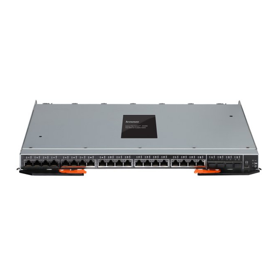
Information panel The front panel of the switch contains information LEDs, four SFP+ module port connectors, one mini-USB serial port connector, and twenty RJ-45 ports. The switch-module information panel contains the following components: Chapter 2. Installing the switch... -
Page 26: Information Leds
(LINK) and activity (TX/RX) LEDs indicate the status of the external ports. . Notes: v A yellow LED on the IBM Flex System chassis is lit when a system error or event has occurred. To identify the error or event, check the IBM Flex System management-module event log or the switch system log. -
Page 27: Port Status Leds
Switch error (!) LED This yellow LED is at the bottom of the switch on the front panel. v When this LED is lit, it indicates a POST failure or critical alert. Note: When this LED is lit, the system-error LED on the IBM Flex System chassis is also lit. - Page 28 192.168.70.122, or 192.168.70.123, depending on the switch bay where it is installed. v If you change the IP address of the switch and restart the IBM Flex System chassis, the switch maintains this new IP address as its default value.
-
Page 29: Establishing A Tcp/Ip Session Through The Management Module
Establishing a TCP/IP session through the management module To establish a TCP/IP session for the switch through the management module, complete the following steps: 1. Log on to the management module as described in the User’s Guide or Command Line Interface Reference Guide for your advanced management module. If necessary, obtain the IP address of the management module from your system administrator. -
Page 30: Configuring The Switch Through The Telnet Interface
External management External ports Description Enabled Enabled The switch can be managed through the management module, a blade server, or a management station that is connected through an external port. Data traffic is allowed on external ports. To enable management through external ports, complete the following steps: 1. -
Page 31: Configuring The Switch Through The Serial-Port Interface
For more information about configuring through the CLI, see the IBM Application Guide for the switch. Configuring the switch through the serial-port interface The mini-USB serial port provides basic communication through a terminal emulation program (such as Hyperterminal). Because messages from the power-on... -
Page 32: Initial Configuration
v Enable frames and the JavaScript program in your Web browser. The following hardware and software are required for the Web interface: v A frame-capable Web-browser program, such as Internet Explorer (version 6.0 or later), Mozilla Firefox (version 1.0.4 or later), or Netscape Navigator (version 4.7 or later) v A computer or workstation with network access to the switch To start the browser-based interface, complete the following steps:... -
Page 33: Chapter 3. Updating The Firmware And Licensing
Determining the level of switch firmware After you install the switch in the IBM Flex System chassis, make sure that the latest firmware is installed on the switch. To determine the level of the firmware that is installed, complete the following steps: 1. -
Page 34: Resetting And Restarting The Switch
all three network entities (TFTP server, management module, and switch IP addresses) are on the same subnet. Otherwise, you must use a router and configure a gateway address on the switch. Use the management-module interface to configure the IP addresses of the management module external interface (eth0) and the switch so that they are both on the same subnet as the TFTP server. -
Page 35: Acquiring Feature Licenses
Find help for the Features on Demand feature activation process v Provide feedback to IBM about the Features on Demand process Note: Your IBM ID and password are required to log into the Features on Demand website. If you are not registered with IBM, go to http://www.ibm.com/ systems/x/fod/ and click My IBM registration in the left navigation pane. - Page 36 1Gb Ethernet Scalable Switch: User's Guide...
-
Page 37: Chapter 4. Solving Problems
OK LED is lit. However, if the switch fails POST, the yellow switch error LED and the system-error LED on the IBM Flex System chassis are lit. An event is stored in the event log in the system status panel of the management module. -
Page 38: Parts Listing
Replaceable components are of three types: v Tier 1 customer replaceable unit (CRU): Replacement of Tier 1 CRUs is your responsibility. If IBM installs a Tier 1 CRU at your request, you will be charged for the installation. v Tier 2 customer replaceable unit (CRU): You may install a Tier 2 CRU yourself or request IBM to install it, at no additional charge, under the type of warranty service that is designated for your server. -
Page 39: Appendix A. Getting Help And Technical Assistance
Appendix A. Getting help and technical assistance Before you call Using the documentation Getting help and information from the World Wide Web © Copyright IBM Corp. 2012... -
Page 40: Software Service And Support
Software service and support Hardware service and support IBM Taiwan product service 1Gb Ethernet Scalable Switch: User's Guide... -
Page 41: Appendix B. Notices
Appendix B. Notices © Copyright IBM Corp. 2012... -
Page 42: Trademarks
IBM, the IBM logo, and ibm.com are trademarks of International Business Machines Corp., registered in many jurisdictions worldwide. Other product and service names might be trademarks of IBM or other companies. A current list of IBM trademarks is available on the web at "Copyright and trademark information" at http://www.ibm.com/legal/copytrade.shtml Adobe and PostScript are either registered trademarks or trademarks of Adobe Systems Incorporated in the United States and/or other countries. -
Page 43: Documentation Format
Documentation format Electronic emission notices Appendix B. Notices... - Page 44 1Gb Ethernet Scalable Switch: User's Guide...
- Page 45 Appendix B. Notices...
- Page 46 This is electromagnetic wave compatibility equipment for business (Type A). Sellers and users need to pay attention to it. This is for any areas other than home. 1Gb Ethernet Scalable Switch: User's Guide...
-
Page 47: Index
Index Ethernet switch module (continued) installation (continued) OK LED 16 procedure (continued) bay locations, IBM Flex System chassis 5 removing or replacing 9 cables for switch 9 blade server expansion card cables for switch module 10 interconnections with expansion card... - Page 48 24 updating the firmwaree 23 RJ-45 cable upgrading the switch firmware 23 connecting 11 disconnecting 12 Web site IBM Flex System documentation 7 serial console cable connecting 10 disconnecting 10 parts listing 28 SFP+ module cable, connecting 11...
- Page 50 Part Number: 88Y7927 Printed in USA (1P) P/N: 88Y7927...