
Related Manuals for Husqvarna 1030 BioClip


Summary of Contents for Husqvarna 1030 BioClip
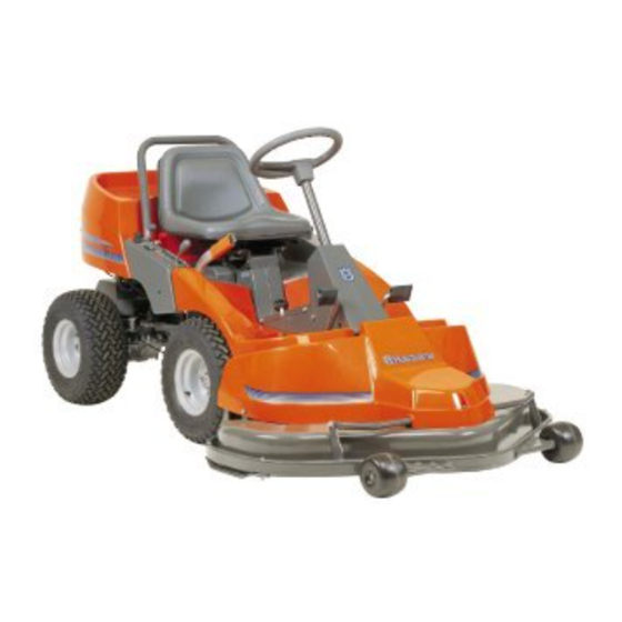
- Page 1 Rider 1030 BioClip Rider 1200 Operator´s manual Please read these instructions carefully and make sure you understand them before using the machine. 101 89 37-26...
- Page 2 Svenska –...
-
Page 3: Table Of Contents
Rider 1030 BioClip and Rider 1200 Safety instructions ... 2 Safety rules for USA ... 2 Explanation of symbols ... 4 Safety instructions ... 5 General use ... 5 Driving on slopes ... 6 Children ... 7 Maintenance ... 7 Presentation... -
Page 4: Safety Instructions
Safe operation practices for ride-on mowers IMPORTANT! This cutting machine is capable of amputating hands and feet and throwing objects. Failure to ob- serve the following safety instructions could result in serious injury or death. General operation 1. Read, understand and follow all instructions in the manual and on the machine before start- ing. - Page 5 SAFETY INSTRUCTIONS IV. Service 1. Use extra care in handling gasoline and other fuels. They are flammable and vapours are explosive. a) Use only an approved container. b) Never remove gas cap or add fuel with the engine running. Allow engine to cool before refuelling.
-
Page 6: Explanation Of Symbols
EXPLANATION OF SYMBOLS These symbols are on the machine and in the instructions. Reverse Neutral Oil pressure Cutting height Use hearing protection Sound level Warning! Rotating blades Never use the machine if persons, especially children, or animals, are in the vicinity –... -
Page 7: Safety Instructions
SAFETY INSTRUCTIONS These instructions are for your safety. Read them carefully. This symbol implies that important safety rules are applicable. This is for your safety and the operating reliability of the machine. General use: • Make yourself familiar with the controls and how to stop quickly. -
Page 8: Driving On Slopes
• Watch out for traffic when working close to a road, or crossing one. • Be careful when rounding a fixed object so that the blades do not hit it. Never drive intentionally over a foreign object. • The machine is heavy and can cause very severe crush injuries. -
Page 9: Children
SAFETY INSTRUCTIONS Do not do the following: • Avoid unnecessary turns on slopes, and if turning is necessary turn slowly and gradually, downwards if possible. • Do not cut close to edges, ditches or banks. The machine can suddenly tip over if a wheel goes over the edge of a drop or a ditch, or if a bank gives way. - Page 10 • Check the fuel level each time before using the machine, and leave space for the fuel to expand since the heat from the engine and hot sun can cause the fuel to run over. • Avoid overfilling. If petrol has been spilt on the machine wipe it up and wait until it has evapor- ated before starting the engine.
-
Page 11: Presentation
Presentation These instructions describe two machine models, Rider 1030 Bioclip and Rider 1200. Rider 1030 Bioclip and Rider 1200 are fitted with Vanguard V-Twin engines from Briggs & Stratton of 18 h.p. The cutting unit on Rider 1200 has rear ejection with a moving width of 1200 mm. -
Page 12: Throttle Control
PRESENTATION Throttle control The throttle control regulates the engine speed, and thereby also the rotation speed of the blades. To increase or reduce the engine speed the control is moved forwards or backwards. Choke lever The choke lever is used for cold starting and to give the engine a richer fuel mixture. -
Page 13: Cutting Unit
Cutting unit Rider 1030 has a Bioclip unit which cuts the grass finely by cutting it several times before it is returned to the lawn as fertiliser. The cutting unit on Rider 1200 has rear ejection, i.e. the grass cuttings are thrown out behind the cutting unit. -
Page 14: Lever For Adjustment Of Cutting Height
Lever for adjustment of the cutting height The cutting height can be adjusted to 7 different positions with the cutting height lever. To achieve an even cutting height it is important that the tyre pressures are the same on the front wheels (60 kPa). -
Page 15: Driving
Before starting • Read the safety instructions and information on the location and function of the controls before starting (see pages 5–12). • Conduct daily maintenance before starting (see maintenance schedule on page 17). • Adjust the seat to the required position. Starting the engine 1. -
Page 16: Driving The Machine
5. When the engine starts release the ignition key immediately back to neutral position. IMPORTANT INFORMATION Do not run the starter for more than about 5 seconds at a time. If the engine does not start, wait about 10 seconds before trying again. -
Page 17: Cutting Tips
3. Select the required cutting height (1–7) with the cutting height lever. 4. Push in the lock button on the lift lever and lower down the cutting unit. Cutting tips WARNING! Clear the lawn from stones and other objects which can be thrown out by the blades. -
Page 18: Stopping The Engine
WARNING! Never drive the machine on ground at an angle of more than 15°. Mow slopes upwards and downwards, never across. Avoid sudden changes in direction. Stopping the engine Preferably allow the engine to idle for a minute to obtain normal working temperature before stopping it if it has been working hard. -
Page 19: Maintenance
The following is a list of the maintenance which should be conducted on the machine. For the items which are not described in these instructions go to an authorised service workshop. Maintenance Check the engine’s oil level Check the engine’s cooling air inlet Check the fuel pump’s air filter Check the transmission’s air inlet Check the transmission’s oil level... -
Page 20: Dismantling Of The Machine Hoods
Dismantling of the machine hoods Engine hood Release the two rubber straps on the rear edge of the engine hood and lift off the hood. Front hood Dismantle the screws (1, 2 and 3) and lift off the front hood. Right-hand fender Dismantle the foot-plate (1), screws (2 and 3), and lift off the fender. -
Page 21: Checking The Engine's Oil Level
MAINTENANCE Check the engine’s oil level Check the oil level in the engine when the machine is horizontal. Dismantle the engine hood as per the description on page 18. Take out the dip stick, wipe off the oil, and insert again. -
Page 22: Checking The Transmission's Air Intake
Check the transmission’s air intake Check that the transmission’s air intake in not blocked. Check the transmission’s oil level 1. Check the transmission’s oil level by looking through the mesh on the air intake. The oil level should lie between the MIN and MAX markings on the oil canister at 20°... -
Page 23: Checking And Adjusting The Steering Wires
Checking and adjustment of the steering wires The steering is controlled by means of wires. These can in time become slack, which implies that the adjustment of the steering becomes altered. Check and adjust the steering as follows: 1. Dismantle the frame-plate by releasing the screws (two on each side). -
Page 24: Checking And Adjusting The Brakes
Checking and adjusting the brake Check that the brake is correctly adjusted by placing the machine on a slight downward slope and applying the brake. If the machine does not stand still the brake should be adjusted. The brake is adjusted as follows: 1. -
Page 25: Replacement Of Air Filter
Replacing the air filter If the engine seems to lack power or does not run smoothly this may be because the air filter is clogged. It is therefore important to replace the air filter at regular intervals (see maintenance schedule on page 17 for correct service interval). -
Page 26: Checking And Adjustment Of Cutting Unit's Ground Pressure
Checking and adjustment of the cutting unit’s ground pressure To achieve the best cutting results the cutting unit should follow the underlying surface without pressing too hard against it. The pressure is adjusted with a screw on each side of the machine. Adjusting of the cutting unit’s ground pressure is conducted as follows: 1. -
Page 27: Checking And Adjusting The Parallelism Of The Cutting Unit
Checking and adjusting the cutting unit’s parallelism To achieve good mowing results it is important that the unit is parallel with the ground. Check this as follows: 1. Place the machine on a level surface. 2. Measure the distance between the ground and the edge of the unit, at the front and back of the hood. -
Page 28: Dismantling The Cutting Unit
Dismantling the cutting unit The cutting unit can be released from the machine for cleaning or checking of the blades and screws. Dismantle the cutting unit as follows: 1. Dismantle the front hood as described on page 2. Dismantle the pull-rod (1). A tool can be used when the needle spring is removed to carefully bend out the pull-rod from its holder. -
Page 29: Changing The Oil
Changing the oil The oil should be changed for the first time after 8 hours of running time. Thereafter it should be changed every 50 hours of running time. If the engine is run hard or during high temperatures the oil should be changed every 25 running hours. -
Page 30: Replacement Of The Oil Filter
Replacement of the oil filter 1. Dismantle the engine hood as described on page 18. 2. Drain off the engine oil according to the work description “Changing of engine oil” on page 27. 3. Dismantle the oil filter. If necessary use a filter extractor. -
Page 31: Checking And Adjustment Of Throttle Wire
Checking and adjustment of the throttle wire Check that the engine responds to the throttle control and that the correct engine speed is achieved at full throttle. If necessary the following adjustment can be made: 1. Release the clamping screw and push the throttle control to full throttle position. -
Page 32: Checking The Tyre Pressure
Checking the tyre pressure The tyre pressure should be 60 kPa (0.6 kp/cm all round. To improve driving the pressure on the rear tyres can be reduced to 40 kPa (0.4 kp/cm The maximum tyre pressure is 100 kPa (1.0 kp/cm IMPORTANT INFORMATION Different tyre pressures on the front tyres will result in the blades cutting the grass at... -
Page 33: Trouble Shooting Schedule
TROUBLE SHOOTING SCHEDULE Problem Engine will not start. Starter does not pull round engine. Engine does not run smoothly. Engine seems to have no power. Engine overheats. Battery does not charge. Machine vibrates. Uneven mowing. Procedure • Fuel tank empty. •... -
Page 34: Storage
Winter storage At the end of the season the machine should immediately be put in order for storage, also if it is going to stand idle for more than 30 days. Fuel which is left to stand for long periods (30 days or more) can leave tacky deposits which can block the carburettor and interfere with the engine. -
Page 35: Wiring Diagram
1. Brake switch, hydrostat 2. Microswitch, cutting unit 3. Microswitch, seat 4. Ignition lock 5. Counter 6. Start relay 7. Engine WIRING DIAGRAM Explanation of colour abbreviations in wiring diagram. R = Red B = Blue W = White BL = Black Y = Yellow BR = Brown English –... -
Page 36: Technical Data
Note that no legal claims are valid on the basis of information in this manual. Use only genuine parts for repairs. The warranty is not valid if non genuine parts are used. – English TECHNICAL DATA Rider 1030 Bioclip, Rider 1200 Rider 1030 Bioclip 2300 mm 1120 mm... - Page 37 English –...
- Page 38 ´*2}h¶6+¨...
- Page 39 English –...
- Page 40 ´*2}h¶6+¨...