
Related Manuals for Cisco RNG200


Summary of Contents for Cisco RNG200
- Page 1 User Guide Cisco RNG200 DVR with Multi-Stream CableCARD Interface RNG200 VOL- VOL+ SELECT POWER MENU INFO EXIT LIST L AUDIO IN R VIDEO IN...
- Page 2 Notice to Installers The servicing instructions in this notice are for use by qualifi ed service personnel only. To reduce the risk of electric shock, do not perform any servicing other than that contained in the operating instructions, unless you are qualifi ed to do so. Note to System Installer For this apparatus, the coaxial cable shield/screen shall be grounded as close as practical to the point of entry of the cable...
-
Page 3: Table Of Contents
Contents Important Safety Instructions ......................iv Welcome ............................1 Safety First ........................... 1 Identify Your Set-Top ........................1 What’s in the Carton? ........................2 Additional Equipment You Might Need ..................2 Front Panel Features ........................3 Back Panel Connectors ........................ 4 Connecting the Set-Top ........................ -
Page 4: Important Safety Instructions
IMPORTANT SAFETY INSTRUCTIONS Read These Instructions Keep These Instructions Heed All Warnings Follow All Instructions Power Source Warning A label on this product indicates the correct power source for this product. Operate this product only from an electrical outlet with the voltage and frequency indicated on the product label. - Page 5 IMPORTANT SAFETY INSTRUCTIONS, continued Provide Ventilation and Select a Location Service Warnings • Do not block any ventilation openings. Install in accordance with the manufacturer’s instructions. WARNING: Avoid electric shock! Do not open • Do not place this apparatus on a bed, sofa, rug, or similar the cover of this product.
-
Page 7: Welcome
Follow the instructions in this guide to install the RNG200, to become familiar with the buttons on the front panel, and to access your cable services. Then, enjoy the features of the RNG200 and change the way you watch TV. -
Page 8: What's In The Carton
EXIT LIST L AUDIO IN R VIDEO IN • RNG200 DVR with M-Card • Quick Reference Guide • Power Cord Additional Equipment You Might Need You might need some of the cables and adapters shown below for connecting the set-top to your home entertainment devices. -
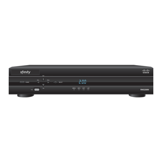
Page 9: Front Panel Features
Front Panel Features RNG200 VOL- VOL+ SELECT POWER MENU INFO EXIT LIST L AUDIO IN R VIDEO IN 7 8 9 10 T13439 1 Power Turns the DVR on and off 2 USB Connects to external USB devices (Reserved for future use) -
Page 10: Back Panel Connectors
Back Panel Connectors OPTICAL ARCHIVE OUT 1 MULTI-STREAM CABLE CARD CAUTION AUDIO DIGITAL RISK OF ELECTRIC SHOCK VIDEO VIDEO AUDIO DO NOT OPEN AVIS: RISQUE DE CHOC M-CARD SN: PKCPKPDBT ELECTRIQUE NE PAS OUVRIR M-CARD MAC: 001AC326910A 120 VAC 60Hz 4.2A 500W THIS DEVICE IS INTENDED TO BE ATTACHED TO A RECEIVER THAT IS NOT USED TO RECEIVE OVER-THE-AIR... -
Page 11: Connecting The Set-Top
Connecting the Set-Top To connect your set-top to your entertainment devices, complete these steps. Determine if your TV is HD or SD and whether it is wide screen (16:9) or standard screen (4:3). See page 11 for more information. Make the connections for your TV and VCR as follows: •... -
Page 12: Connections For An Hdtv And Vcr
Connections for an HDTV and VCR To use the set-top with an HDTV, you must make one of the following connections to view the HD content. In addition, you can make connections to a digital or analog VCR to record to a VCR tape. Refer to your TV and VCR user guides and the cabling diagrams in this guide for more detailed connection information. -
Page 13: Connections For A Standard-Defi Nition Tv And Vcr
Connections for a Standard-Defi nition TV and VCR When using the set-top with an SDTV, you must make one of the following connections to view content. Some SDTVs may not have all these connections. In addition, you can make connections to a VCR to record to a VCR tape. Refer to your TV and VCR user guides and the cabling diagrams in this guide for more detailed information. -
Page 14: View Television Programming
View Television Programming Access Services and Programs Access cable services and programs by pressing the following keys on the remote control: • Guide–Access the on-screen guide. The on-screen guide displays schedules of TV programs and other services available from your cable service provider, such as video-on-demand and pay-per-view programs. •... -
Page 15: Troubleshooting
Troubleshooting If the set-top does not perform as expected, the following tips may help. If you need further assistance, contact your service provider. No Picture • Verify that the M-Card module is installed. • Verify that the power to your TV is turned on. •... -
Page 16: Frequently Asked Questions
Frequently Asked Questions What is Digital Television? Digital television (DTV) is a huge leap forward in television technology compared to analog television that has been widely available since the 1940s. DTV is delivered and displayed using digital encoding, similar to the way a PC operates. -
Page 17: Picture Formats
Picture Formats What is the Difference Between a Standard-Screen and a Wide-Screen HDTV? The type of screen your HDTV has (wide screen or standard screen) determines how the set-top displays programs on the screen. The picture format for an HDTV is a combination of aspect ratio and screen resolution and is different for standard-screen and wide-screen HDTVs. -
Page 18: Connecting To An Hdtv With An Hdmi Connector
Connecting to an HDTV with an HDMI Connector WARNING: Electric shock hazard! Unplug all electronic devices before connecting or disconnecting any device cables to the set-top. Required cables: • 1 HDMI-to-HDMI cable RNG200 OPTICAL OPTICAL ARCHIVE ARCHIVE OUT 1 OUT 1... -
Page 19: Connecting To An Hdtv With A Dvi Connector
Electric shock hazard! Unplug all electronic devices before connecting or disconnecting any device cables to the set-top. Required cables: • 1 HDMI-to-DVI or 1 HDMI-to-HDMI cable and 1 DVI adapter • 1 audio Left/Right cable RNG200 OPTICAL OPTICAL ARCHIVE ARCHIVE OUT 1 OUT 1... -
Page 20: Connecting To An Hdtv With Component Input (Prpby)
Electric shock hazard! Unplug all electronic devices before connecting or disconnecting any device cables to the set-top. Required cables: • 1 set component video cables (PrPbY) • 1 audio Left/Right cable RNG200 OPTICAL OPTICAL ARCHIVE ARCHIVE OUT 1 OUT 1... -
Page 21: Connecting To A Home Theater System With Component Input (Prpby)
Required cables: • 3 sets component video cables (PrPbY) • 1 audio Left/Right cable • 2 coaxial digital audio cables RNG200 OPTICAL OPTICAL ARCHIVE ARCHIVE OUT 1 OUT 1 OUT 1 MULTI-STREAM CABLE CARD... -
Page 22: Connecting To A Stereo Vcr And Hdtv (Optional)
Electric shock hazard! Unplug all electronic devices before connecting or disconnecting any device cables to the set-top. Required cables: • 1 RF coaxial cable • 2 sets composite A/V cables RNG200 OPTICAL OPTICAL ARCHIVE ARCHIVE OUT 1 OUT 1 OUT 1... -
Page 23: Connecting The Set-Top In Hd Mode To An Sdtv With Component Input (Prpby)
Electric shock hazard! Unplug all electronic devices before connecting or disconnecting any device cables to the set-top. Required cables: • 1 set component video cables (PrPbY) • 1 audio Left/Right cable RNG200 OPTICAL OPTICAL ARCHIVE ARCHIVE OUT 1 OUT 1... -
Page 24: Index
Index Dashes display Outlet iv, 4 Diagrams. See Connecting the set-top to other devices Power input Digital TV, What is it Aspect ratio Display, LED DVI connector 2, 4, 6, 13 Back panel Burn-in of screen FAQs FCC compliance Formats, picture 1, 2, 4, 9 CableCARD Frequently Asked Questions. - Page 25 Index, continued Keys. See Front panel; Back panel S-Video 6, 7 Safety ii, iv-v LED Display Scan rates Screen burn-in M-Card. See Multi-Stream CableCARD resolution Multi-Stream CableCARD 1, 2, 4, 9 size SD mode 5, 17 SDTV Connections 7, 17 Picture What is it Doesn’t display...
- Page 26 Index, continued Updating software USB port VCR connection 6, 7, 16 View programs Watch TV 1, 8 Web access to product information Welcome Widescreen TV YPbPr. See PrPbY Zoom picture 8, 11...
-
Page 27: Compliance Information
If this equipment does cause harmful interference Cisco Systems, Inc. assumes no responsibility for errors or omissions to radio or television reception, which can be determined by that may appear in this guide. - Page 28 Box 465447 Lawrenceville, GA 30042 Cisco, Cisco Systems, the Cisco logo, the Cisco Systems logo, and Scientifi c Atlanta are registered trademarks or trademarks of Cisco Systems, Inc. and/or its affi liates in the U.S. and certain other countries. CableCARD and M-Card are trademarks of Cable Television Laboratories, Inc.