Honda FC600 Owner's Manual
Tiller
Hide thumbs
Also See for FC600:
- Owner's manual (60 pages) ,
- Owner's manual (60 pages) ,
- Owner's manual (60 pages)
Table of Contents
Advertisement
Advertisement
Table of Contents

Related Manuals for Honda FC600


Summary of Contents for Honda FC600
- Page 1 Owner s Manual TILLER FC600 2012 Honda Motor Co., Ltd. -All Rights Reserved...
- Page 2 The information and specifications included in this publication were in effect at the time of approval for printing. Honda Motor Co., Ltd. reserves the right, however, to discontinue or change specifications or design at any time...
- Page 3 INTRODUCTION Congratulations on your selection of a Honda tiller. We are certain you will be pleased with your purchase of one of the finest tillers on the market. We want to help you get the best results from your new tiller and to operate it safely.
- Page 4 INTRODUCTION A FEW WORDS ABOUT SAFETY Your safety and the safety of others are very important. And using this tiller safely is an important responsibility. To help you make informed decisions about safety, we have provided operating procedures and other information on labels and in this manual. This information alerts you to potential hazards that could hurt you or others.
-
Page 5: Table Of Contents
CONTENTS TILLER SAFETY ..................5 IMPORTANT SAFETY INFORMATION ..........5 SAFETY LABEL LOCATIONS..............8 CONTROLS ....................9 COMPONENT & CONTROL LOCATIONS ..........9 CONTROLS..................10 Fuel Valve ..................10 Choke Lever ..................10 Engine Switch.................. 10 Starter Grip ..................11 Throttle Lever .................. - Page 6 Carburetor Modification for High Altitude Operation......52 Emission Control System Information ..........53 Air Index ..................55 Specifications .................. 56 CONSUMER INFORMATION ..............57 Dealer Locator Information .............. 57 Honda Publications ................. 57 Customer Service Information ............58 QUICK REFERENCE INFORMATION......Inside back cover...
-
Page 7: Tiller Safety
TILLER SAFETY IMPORTANT SAFETY INFORMATION Honda tillers are designed to cultivate earth outdoors. Other uses can result in injury to the operator or damage to the tiller and other property. Most injuries or property damage can be prevented if you follow all instructions in this manual and on the tiller. - Page 8 TILLER SAFETY Fire and Burn Hazards • The exhaust system gets hot enough to ignite some materials. — Keep the tiller at least 3 feet (1 meter) away from buildings and other equipment during operation. — Keep flammable materials away from the tiller. •...
- Page 9 TILLER SAFETY Keep Shields in Place Guards and shields are designed to protect you from being hit by thrown objects and to keep you from touching hot engine parts and moving components. For your safety and the safety of others, keep all shields in place when the engine is running.
-
Page 10: Safety Label Locations
SAFETY LABEL LOCATIONS These labels warn you of potential hazards that can cause serious injury. Read them carefully. If a label comes off or becomes hard to read, contact your Honda servicing dealer for a replacement. WARNING TO AVOID SERIOUS INJURY •... -
Page 11: Controls
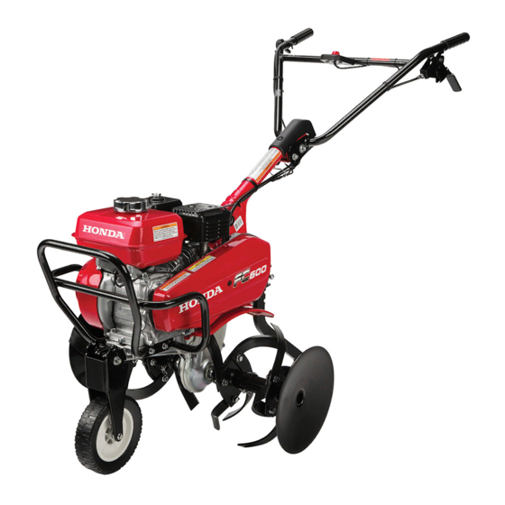
CONTROLS COMPONENT & CONTROL LOCATIONS ENGINE SWITCH FUEL TANK CAP MUFFLER HANDLEBAR FRONT WHEEL V-BELT COVER THROTTLE LEVER SPARK PLUG CAP CLUTCH LEVER AIR CLEANER COVER HANDLEBAR HEIGHT ADJUSTER STARTER DRAG BAR GRIP TRANSMISSION OIL FILLER CAP... -
Page 12: Controls
CONTROLS CONTROLS Fuel Valve The fuel valve opens and closes the connection between the fuel tank and the carburetor. FUEL VALVE The fuel valve must be in the ON position for the engine to run. After stopping the engine, turn the fuel valve to the OFF position. -
Page 13: Starter Grip
CONTROLS Starter Grip Pulling the starter grip operates the STARTER GRIP recoil starter to crank the engine for starting. Throttle Lever The throttle lever controls engine speed. THROTTLE LEVER Moving the throttle lever in the directions shown makes the engine run faster or slower. Tine speed is controlled by adjusting the throttle lever. -
Page 14: Clutch Lever
CONTROLS Clutch Lever The clutch lever engages and ENGAGED disengages the transmission that drives the tines. CLUTCH LEVER DISENGAGED Drag Bar The drag bar controls tilling depth DRAG BAR and should always be used when tilling. It enables you to compensate for the hardness of the soil. -
Page 15: Front Wheel
CONTROLS Front Wheel The front wheel is used to help move the tiller from one place to another. Lift the tiller by the handlebars to roll the tiller on the front wheel. Return the wheel to the raised position before tilling. Always stop the engine before lowering or raising the wheel. -
Page 16: Before Operation
BEFORE OPERATION ARE YOU READY TO GET STARTED? Your safety is your responsibility. A little time spent in preparation will significantly reduce your risk of injury. Knowledge Read and understand this manual. Know what the controls do and how to operate them. -
Page 17: Check The Engine
BEFORE OPERATION Do not place flammable objects close to the engine. Before beginning your pre-operation checks, be sure the tiller is on a level surface and the engine switch is in the OFF position. Check the Engine Check the oil level (see page 28). Check the air filter (see page 32). -
Page 18: Operation
OPERATION SAFE OPERATING PRECAUTIONS Before operating the tiller for the first time, please review both the TILLER SAFETY chapter and the chapter titled BEFORE OPERATION. For your safety, do not start or operate the tiller in an enclosed area such as a garage. -
Page 19: Starting The Engine
OPERATION STARTING THE ENGINE Refer to Safe Operating Precautions on page 16. Tines are sharp and spin fast. Spinning tines can cut you severely and can amputate body parts. • Wear protective footwear. • Keep your hands and feet away from the tines while the engine is running. - Page 20 OPERATION 3. Turn the engine switch to the ON position. ENGINE SWITCH 4. Move the throttle lever away from the SLOW position, about 1/3 of the way toward the FAST position. THROTTLE LEVER SLOW 5. Pull the starter grip lightly until STARTER GRIP you feel resistance, then pull briskly in the direction of the...
- Page 21 OPERATION 6. If the choke lever was moved to the CLOSED position to start the engine, gradually move it to the OPEN position as the engine warms up. CHOKE LEVER OPEN CLOSED...
-
Page 22: Operating The Controls For Tilling
OPERATION OPERATING THE CONTROLS FOR TILLING If the tines dig in but the machine will not move forward, move the handlebars from side-to-side. When turning, push down on the handlebars to bring the tiller’s weight to the rear; this will make turning easier. Handlebar Height Adjustment 10 x 85 mm HANDLEBAR... - Page 23 OPERATION Tilling Depth Adjustment DRAG BAR The drag bar is used to control the tilling depth, which can be adjusted by removing the pin and lock pin and sliding the drag bar up and down as necessary. During operation, if the machine jerks forward while tilling, press down on the handlebars.
-
Page 24: Stopping The Engine
OPERATION STOPPING THE ENGINE To stop the engine in an emergency, simply turn the engine switch to the OFF position. Under normal conditions, use the following procedure. ENGAGED 1. Release the clutch lever to the DISENGAGED position. CLUTCH LEVER DISENGAGED 2. -
Page 25: Servicing Your Tiller
Remember that your authorized Honda servicing dealer knows your tiller best and is fully equipped to maintain and repair it. To ensure the best quality and reliability, use only new, Honda Genuine parts or their equivalents for repair and replacement. -
Page 26: Maintenance Safety
SERVICING YOUR TILLER MAINTENANCE SAFETY Some of the most important safety precautions follow. However, we cannot warn you of every conceivable hazard that can arise in performing maintenance. Only you can decide whether or not you should perform a given task. Failure to properly follow maintenance instructions and precautions can cause you to be... -
Page 27: Maintenance Schedule
(1) Service every 10 operation hours or every day when used in dusty areas. (2) These items should be serviced by your servicing dealer, unless you have the proper tools and are mechanically proficient. Refer to Honda shop manual for service procedures. -
Page 28: Refueling
SERVICING YOUR TILLER REFUELING Remove the fuel tank cap and check the fuel level with the tiller on a level surface. If the fuel level is low, refuel in a well-ventilated area with the engine stopped. If the engine has been running, allow it to cool first. Never refuel the engine inside a building where gasoline fumes can reach flames or sparks. -
Page 29: Fuel Recommendations
SERVICING YOUR TILLER FUEL RECOMMENDATIONS This engine is certified to operate on unleaded gasoline with a pump octane rating of 86 or higher. Never use stale or contaminated gasoline or an oil/gasoline mixture. Avoid getting dirt or water in the fuel tank. You may use regular unleaded gasoline containing no more than 10% ethanol (E10) or 5% methanol by volume. -
Page 30: Engine Oil Level Check
SERVICING YOUR TILLER ENGINE OIL LEVEL CHECK Check the engine oil level with the tiller on a level surface and the engine stopped. 1. Remove the oil filler cap/dipstick and wipe it clean. 2. Insert and remove the dipstick without screwing it into the filler neck. Check the oil level shown on the dipstick. -
Page 31: Engine Oil Change
SERVICING YOUR TILLER ENGINE OIL CHANGE Drain the oil while the engine is warm to assure rapid and complete draining. 1. Place a suitable container below the engine to catch the used oil, and then remove the oil filler cap/dipstick, drain plug, and sealing washer. 2. -
Page 32: Engine Oil Recommendations
AMBIENT TEMPERATURE The SAE oil viscosity and service category are in the API label on the oil container. Honda recommends that you use API SERVICE category SJ or later (or equivalent) oil. -
Page 33: Servicing Your Tiller (Continued)
SERVICING YOUR TILLER TRANSMISSION OIL LEVEL CHECK Check the transmission oil level with the tiller on a level surface and the engine stopped. 1. Remove the transmission oil filler cap. The oil should be level with the lower edge of the oil filler hole. 2. -
Page 34: Air Filter Inspection
SERVICING YOUR TILLER AIR FILTER INSPECTION WING NUT 1. Unscrew the wing nut and remove the air cleaner cover. PAPER WING NUT ELEMENT Check the air filter elements to be sure they are clean and in good condition. FOAM ELEMENT 2. - Page 35 SERVICING YOUR TILLER 3. Clean both filter elements if they are to be reused. Foam element: Clean in warm soapy water, rinse and allow to dry thoroughly. Or clean in high flash point solvent and allow to dry. Dip the element in clean engine oil and squeeze out all the excess.
-
Page 36: Spark Plug Service
SERVICING YOUR TILLER SPARK PLUG SERVICE Recommended spark plug: BPR5ES (NGK) W16EPR-U (DENSO) An incorrect spark plug can cause engine damage. 1. Disconnect the spark plug cap, and remove any dirt from around the spark plug area. 2. Remove the spark plug with a 13/16-inch spark plug wrench. 3. - Page 37 SERVICING YOUR TILLER If reinstalling a used spark plug, tighten 1/8 – 1/4 turn after the spark plug seats. If installing a new spark plug, tighten 1/2 turn after the spark plug seats. A loose spark plug can overheat and damage the engine. Overtightening the spark plug can damage the threads in the cylinder head.
-
Page 38: Clutch Cable Adjustment
SERVICING YOUR TILLER CLUTCH CABLE ADJUSTMENT There should be 0.1 – 0.3 in (3 – 8 mm) of free play at the lever end. If the lever adjustment is incorrect, loosen the lock nut and turn the adjusting bolt in or out just enough to obtain the correct free play. Tighten the lock nut securely after adjustment. -
Page 39: Drive Belt Adjustment
SERVICING YOUR TILLER DRIVE BELT ADJUSTMENT 1. Stop the engine, and remove the spark plug cap. 2.4 – 2.6 in 2. Remove the 6 x 50 mm flange (60 – 65 mm) bolt from the V-belt cover and remove the V-belt cover. 3. - Page 40 SERVICING YOUR TILLER 6. After adjustment has been completed, fasten the belt stopper bolts securely. 7. Install the belt cover. After checking or adjusting the drive belt, be sure to reinstall the belt cover. The cover is designed to help shield you from the moving belt and pulleys. Contact with the moving belt or pulleys may cause you or your clothing to get caught in the moving...
-
Page 41: Sediment Cup Cleaning
SERVICING YOUR TILLER SEDIMENT CUP CLEANING 1. Move the fuel valve to the OFF position, and then remove the fuel sediment cup, O-ring, and filter. Gasoline is highly flammable and explosive. You can be burned or seriously injured when handling fuel. •... -
Page 42: Spark Arrester Service
Your engine is not factory-equipped with a spark arrester. In some areas, it is illegal to operate an engine without a spark arrester. Check local laws and regulations. A spark arrester is available from authorized Honda servicing dealers. The spark arrester must be serviced every 6 months or 100 hours to keep it functioning as designed. -
Page 43: Storage
STORAGE STORAGE PREPARATION Proper storage preparation is essential for keeping your tiller trouble free and looking good. The following steps will help to keep rust and corrosion from impairing your tiller’s function and appearance, and will make the engine easier to start when you use the tiller again. Cleaning 1. -
Page 44: Fuel
STORAGE 2. After washing the tiller, wipe dry all accessible surfaces. 3. Start the engine outdoors, and let it run until it reaches normal operating temperature to evaporate any water remaining on the engine. 4. While the engine is running, operate the clutch lever to expel water from the pulleys, belt, and other moving items. - Page 45 STORAGE The Distributor’s Limited Warranty does not cover fuel system damage or engine performance problems resulting from neglected storage preparation. You can extend fuel storage life by adding a gasoline stabilizer that is formulated for that purpose, or you can avoid fuel deterioration problems by draining the fuel tank and carburetor.
- Page 46 STORAGE Draining the Fuel Tank and Carburetor 1. Place an approved gasoline container below the carburetor, and use a funnel to avoid spilling fuel. 2. Loosen the fuel drain knob, and then move the fuel valve to the ON position. Gasoline is highly flammable and explosive.
-
Page 47: Engine Oil
STORAGE Engine Oil 1. Change the engine oil (see page 29). 2. Remove the spark plug (see page 34). 3. Pour a teaspoon (5 cc) of clean engine oil into the cylinder. 4. Gently pull the starter grip several times to distribute the oil in the cylinder. 5. -
Page 48: Storage Precautions
STORAGE STORAGE PRECAUTIONS If your tiller will be stored with gasoline in the fuel tank and carburetor, it is important to reduce the hazard of gasoline vapor ignition. Select a well ventilated storage area away from any appliance that operates with a flame, such as a furnace, water heater, or clothes dryer. -
Page 49: Transporting
TRANSPORTING BEFORE LOADING If the engine has been running, allow it to cool for at least 15 minutes before loading the tiller on the transport vehicle. A hot engine and exhaust system can burn you and can ignite some materials. Always turn the ignition switch to the OFF position. -
Page 50: Taking Care Of Unexpected Problems
Spark plug wet with fuel (flooded Dry and reinstall spark plug. engine). Start engine with throttle lever in FAST position. Fuel filter clogged, carburetor Take the tiller to an authorized malfunction, ignition malfunction, Honda servicing dealer, or refer to valves stuck, etc. the shop manual. -
Page 51: Engine Lacks Power
(p. 44). refueled with bad gasoline. Refuel with fresh gasoline (p. 26). Fuel filter clogged, carburetor Take the tiller to an authorized malfunction, ignition malfunction, Honda servicing dealer, or refer to valves struck, etc. the shop manual. -
Page 52: Poor Tilling Quality
TAKING CARE OF UNEXPECTED PROBLEMS TILLER POOR TILLING QUALITY Possible Cause Correction Engine speed is too slow for soil Move the throttle to FAST position conditions. (p. 11). Tiller is moving too fast for soil Reduce throttle speed (p. 11). conditions. -
Page 53: Technical Information
TECHNICAL INFORMATION Serial Number Locations ENGINE SERIAL NUMBER FRAME SERIAL NUMBER Record the engine and frame serial numbers in the spaces below. You will need these serial numbers when ordering parts, and when making technical or warranty inquires. (see page 58) Engine serial number:__________________________________________ Frame serial number: __________________________________________ Date purchased: ______________________________________________... -
Page 54: Carburetor Modification For High Altitude Operation
TECHNICAL INFORMATION Carburetor Modification for High Altitude Operation At high altitude, the standard carburetor air-fuel mixture will be too rich. Performance will decrease, and fuel consumption will increase. A very rich mixture will also foul the spark plug and cause hard starting. Operation at an altitude that differs from that at which this engine was certified, for extended periods of time, may increase emissions. -
Page 55: Emission Control System Information
The following instructions and procedures must be followed in order to keep the emissions from your Honda engine within the emission standards. Tampering and Altering Tampering is a violation of Federal and California law. - Page 56 • Black exhaust smoke or high fuel consumption. Replacement Parts The emission control systems on your new Honda engine were designed, built, and certified to conform with EPA and California emission regulations. We recommend the use of Honda Genuine parts whenever you have maintenance done.
-
Page 57: Air Index
TECHNICAL INFORMATION Air Index (Models sold in California) An Air Index Information hang tag/label is applied to engines certified to an emission durability time period in accordance with the requirements of the California Air Resources Board. The bar graph is intended to provide you, our customer, the ability to compare the emissions performance of available engines. -
Page 58: Specifications
TECHNICAL INFORMATION Specifications Model FC600 Type A type Description code FAMJ Dry mass [weight] 126 lbs (57 kg) Length 59.3 in (1,505 mm) Width 26.4 in (670 mm) Height 39.2 in (995 mm) Engine model GX160 Engine type 4-stroke, 1-cylinder, OHV, forced air cooled Displacement 9.9 cu-in (163 cm... -
Page 59: Consumer Information
Shop Manual This manual covers complete maintenance and overhaul procedures. It is intended to be used by a skilled technician. Available through your Honda dealer or through Helm Inc. at 1 (888) 292- 5395 or visit http://powerequipment.honda.com/support/shop-manuals Parts Catalog This manual provides complete, illustrated parts lists. Available through your Honda dealer. -
Page 60: Customer Service Information
CONSUMER INFORMATION Customer Service Information Honda Power Equipment dealership personnel are trained professionals. They should be able to answer any question you may have. If you encounter a problem that your dealer does not solve to your satisfaction, please discuss it with the dealership’s management. The Service Manager or General Manager can help. - Page 61 MEMO...
- Page 62 MEMO...
-
Page 63: Quick Reference Information
QUICK REFERENCE INFORMATION Unleaded gasoline with an ethanol content of no more than 10% and a Fuel Type pump octane rating of 86 or higher (page SAE 10 W-30, API SJ or later, for general Engine Oil Type use (page 30) Maximum oil capacity: 19.6 oz (0.58 L) Spark Plug Type... - Page 64 600.2012.05 31733720 Printed in Japan 00X31-733-7200...