Table of Contents
Advertisement
Quick Links
Advertisement
Table of Contents
Troubleshooting

Related Manuals for Cisco 7401ASR


Summary of Contents for Cisco 7401ASR
- Page 1 Cisco 7401ASR Installation and Configuration Guide Corporate Headquarters Cisco Systems, Inc. 170 West Tasman Drive San Jose, CA 95134-1706 http://www.cisco.com Tel: 408 526-4000 800 553-NETS (6387) Fax: 408 526-4100 Customer Order Number: Text Part Number: OL-5419-01 B0...
- Page 2 You can determine whether your equipment is causing interference by turning it off. If the interference stops, it was probably caused by the Cisco equipment or one of its peripheral devices. If the equipment causes interference to radio or television reception, try to correct the interference by using one or more of the following measures: •...
-
Page 3: Table Of Contents
Installing and Removing the Gigabit Interface Converter Installing and Removing a Port Adapter or Service Adapter 1-10 Replacing the SDRAM DIMM 1-11 Removing the Cover 1-12 Removing and Installing the SDRAM DIMM 1-13 Cisco 7401ASR Installation and Configuration Guide OL-5419-01 B0... - Page 4 Contents Replacing the Cover 1-14 Rack-Mounting, Tabletop Installation, and Cabling C H A P T E R Preparing to Install the Cisco 7401ASR Router Tools and Parts Required Electrical Equipment Guidelines Safety Guidelines Preventing Electrostatic Discharge Damage Electrostatic Discharge Prevention...
- Page 5 Creating Crypto Access Lists Defining Transform Sets Creating Crypto Map Entries Verifying the Configuration Troubleshooting C H A P T E R Troubleshooting Overview Problem Solving Using a Subsystems Approach Identifying Startup Problems Cisco 7401ASR Installation and Configuration Guide OL-5419-01 B0...
- Page 6 Using the show pxf interface Command Using the show pxf feature ? Command and Subcommands Using the CompactFlash Disk A P P E N D I X Hardware and Software Requirements Tools and Parts Required Cisco 7401ASR Installation and Configuration Guide OL-5419-01 B0...
- Page 7 Bit 11 and Bit 12 Bit 13 Bit 15 Displaying the Configuration Register While Running Cisco IOS Displaying the Configuration Register While Running ROM Monitor Setting the Configuration Register While Running Cisco IOS Setting the Configuration Register While Running ROM Monitor...
- Page 8 Contents Cisco 7401ASR Installation and Configuration Guide viii OL-5419-01 B0...
- Page 9 Obtaining Additional Publications and Information, page xx • Audience To use this publication, you should be familiar not only with Cisco router hardware and cabling but also with electronic circuitry and wiring practices. You should also have experience as an electronic or electromechanical technician.
-
Page 10: Preface
Terminal sessions and information the system displays are in font. screen screen font Information you must enter is in font. boldface screen boldface screen italic screen font Arguments for which you supply values are in italic screen font. Cisco 7401ASR Installation and Configuration Guide OL-5419-01 B0... - Page 11 Means reader take note. Notes contain helpful suggestions or references to materials not contained in Note this manual. Caution Means reader be careful. You are capable of doing something that might result in equipment damage or loss of data. Cisco 7401ASR Installation and Configuration Guide OL-5419-01 B0...
-
Page 12: Warning Definition
Tässä asiakirjassa esitettyjen varoitusten käännökset löydät laitteen mukana toimitetuista ohjeista. Huomautus SÄILYTÄ NÄMÄ OHJEET Huomautus Tämä asiakirja on tarkoitettu käytettäväksi yhdessä tuotteen mukana tulleen asennusoppaan kanssa. Katso lisätietoja asennusoppaasta, kokoonpano-oppaasta ja muista mukana toimitetuista asiakirjoista. Cisco 7401ASR Installation and Configuration Guide OL-5419-01 B0... - Page 13 Nota La presente documentazione va usata congiuntamente alla guida di installazione specifica spedita con il prodotto. Per maggiori informazioni, consultare la Guida all'installazione, la Guida alla configurazione o altra documentazione acclusa. Cisco 7401ASR Installation and Configuration Guide xiii OL-5419-01 B0...
- Page 14 OBS! SPARA DESSA ANVISNINGAR OBS! Denna dokumentation ska användas i samband med den specifika produktinstallationshandbok som medföljde produkten. Se installationshandboken, konfigurationshandboken eller annan bifogad ytterligare dokumentation för närmare detaljer. Cisco 7401ASR Installation and Configuration Guide OL-5419-01 B0...
-
Page 15: Terms And Acronyms
DCE—data communications equipment • DMA—direct memory access • DTE—data terminal equipment • EPROM—erasable programmable read-only memory • EEPROM—electrically erasable programmable read-only memory • Cisco 7401ASR Installation and Configuration Guide OL-5419-01 B0... - Page 16 Primary cache is closest to the processor core and has the fastest access. Secondary cache has slower access than primary cache, but faster access than tertiary cache. • PXF—Parallel eXpress Forwarding: A secondary processor used to accelerate Cisco IOS services RFI—radio frequency interference • RISC—reduced instruction set computing •...
-
Page 17: Related Documentation
Preface Related Documentation Related Documentation Your Cisco 7401ASR router and the Cisco IOS software running on it contain extensive features and functionality, which are documented in the following resources: Cisco Documentation CD-ROM package (See the “Obtaining Documentation” section on •... -
Page 18: Documentation Feedback
Use the Cisco Product Identification (CPI) tool to locate your product serial number before submitting a web or phone request for service. You can access the CPI tool from the Cisco Technical Support Website by clicking the Tools & Resources link under Documentation & Tools. Choose Cisco Product Identification Tool from the Alphabetical Index drop-down list, or click the Cisco Product Identification Tool link under Alerts &... -
Page 19: Submitting A Service Request
Cisco TAC engineer. The TAC Service Request Tool is located at this URL: http://www.cisco.com/techsupport/servicerequest For S1 or S2 service requests or if you do not have Internet access, contact the Cisco TAC by telephone. (S1 or S2 service requests are those in which your production network is down or severely degraded.) Cisco TAC engineers are assigned immediately to S1 and S2 service requests to help keep your business operations running smoothly. -
Page 20: Obtaining Additional Publications And Information
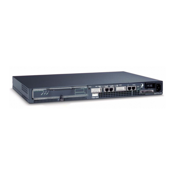
Cisco Marketplace, the company store, at this URL: http://www.cisco.com/go/marketplace/ • The Cisco Product Catalog describes the networking products offered by Cisco Systems, as well as ordering and customer support services. Access the Cisco Product Catalog at this URL: http://cisco.com/univercd/cc/td/doc/pcat/ •... - Page 21 C H A P T E R Overview and Parts Installation The Cisco 7401ASR router provides application-specific features for broadband subscriber aggregation and network application services with high processing performance. This chapter provides a quick hardware overview and options installation instructions for the Cisco 7401ASR router.
-
Page 22: Overview And Parts Installation
Chapter 1 Overview and Parts Installation Hardware Overview The following sections provide illustrations and a brief overview of the Cisco 7401ASR router: Front View, page 1-2 • • LEDs, page 1-3 • Rear View, page 1-4 • System Board, page 1-4 •... -
Page 23: Leds
LEDs LED information is in Figure 1-2 and the table below Figure 1-2. Figure 1-2 LEDs on the Cisco 7401ASR Router In the Power Up LED flashes when there is No. LED Label Color state, the LED is traffic GBIC 0 ENABLE... -
Page 24: Rear View
Cisco 7401ASR Router—Rear View Fan vent Grounding connector The rear of the Cisco 7401ASR router has five fan airflow vents and the chassis grounding connector that provides a chassis ground connection for ESD equipment or a two-hole grounding lug. (See Figure 1-3.) -
Page 25: System Management Functions
Use the Cisco 7401ASR Components List to check the contents of the Cisco 7401ASR router shipping container. Do not discard the shipping container. You need the container if you move or ship the Cisco 7401ASR router in the future. Table 1-1... -
Page 26: Installation Checklist
“Site Requirement Guidelines” section on page 2-4. To assist you with your installation and to provide a historical record of what was done by whom, photocopy the Cisco 7401ASR Router Installation Checklist, Table 1-2 on page 1-6. Indicate when each procedure or verification is completed. -
Page 27: Installing The Compactflash Disk, Gbic, And Port Adapter
You may have ordered a CompactFlash Disk, Gigabit Interface Converter (GBIC), and one of a variety of port adapters or service adapter with your Cisco 7401ASR router. You must install the CompactFlash Disk, GBIC, and port adapter service adapter. Use the installation instructions in the following sections to install or remove one of these optional parts: •... -
Page 28: Installing And Removing The Gigabit Interface Converter
• The CompactFlash Disk supports online insertion and removal (OIR). • Use the CompactFlash Disk to store your configuration files and Cisco IOS software image. • For complete information about using a CompactFlash Disk, see Appendix C, “Using the CompactFlash Disk.”... - Page 29 Overview and Parts Installation Installing the CompactFlash Disk, GBIC, and Port Adapter Class 1 LED product. Warning Figure 1-6 Inserting a GBIC into the Cisco 7401ASR Gigabit Ethernet Slot 0 Gigabit Interface Converter (GBIC) GBIC port 1 Alignment groove Plug...
-
Page 30: Installing And Removing A Port Adapter Or Service Adapter
The Cisco 7401ASR router supports OIR of the port adapter. However, if you choose to power off the router to remove or install a port adapter, turn the power switch to the off position and then remove the power cable. -
Page 31: Replacing The Sdram Dimm
Step 5 Locate the port adapter slot guides inside the Cisco 7401ASR router. They are near the top, and are recessed about one-half inch. The port adapter must slide into the slot guides under the chassis lid. Do not allow the port adapter Caution components to come in contact with the system board or the port adapter could be damaged. -
Page 32: Removing The Cover
To replace or upgrade the SDRAM DIMM, follow these instructions: Removing the Cover The Cisco 7401ASR router cover fits tightly on the chassis. Follow these instructions to remove the cover: Power off the router by turning the power switch to the off position. -
Page 33: Removing And Installing The Sdram Dimm
Figure 1-10 Removing and Replacing the DIMM Spring latch on DIMM socket Notch DIMM Step 1 Attach an ESD-preventative wrist strap between you and an unpainted router surface. Locate the DIMM. Step 2 Cisco 7401ASR Installation and Configuration Guide 1-13 OL-5419-01 B0... -
Page 34: Replacing The Cover
Replace the cover; lower it onto the chassis and push the cover toward the rear of the chassis to lock it in place. Step 2 Replace and tighten the four cover screws. Replace the Cisco 7401ASR router in the rack. See Chapter 2, “Rack-Mounting, Tabletop Installation, and Cabling” for instructions. -
Page 35: Preparing To Install The Cisco 7401Asr Router
Rack-Mounting, Tabletop Installation, and Cabling This chapter explains how to install a Cisco 7401ASR router in a rack in a general tabletop or workbench installation, how to attach cables, and how to power on the router. This chapter contains the following sections: •... -
Page 36: Tools And Parts Required
Chassis fully configured with a port adapter ~ 10.5 lb (4.76 kg) Tools and Parts Required Your Cisco 7401ASR chassis is fully assembled at the factory; no assembly is required. However, you need the following tools and equipment to install the chassis and the rack-mount and cable-management... -
Page 37: C H A P T E R 2 Rack-Mounting, Tabletop Installation, And Cabling
Chapter 2 Rack-Mounting, Tabletop Installation, and Cabling Preparing to Install the Cisco 7401ASR Router Grounding lug and wires: • A grounding lug with two number-10 screw holes with a 0.63-inch (16.002-mm) spacing – between them A wire receptacle large enough to accept a 6-AWG multistrand, copper wire –... -
Page 38: Safety Guidelines
104°F (0°C through 40°C), and keep the area around the chassis as free from dust as is practical. Planning a proper location for the Cisco 7401ASR router and the layout of your equipment rack or wiring closet is essential for successful system operation. Equipment placed too close together or inadequately ventilated can cause system overtemperature conditions. -
Page 39: Installing The Router
Cisco 7401ASR Regulatory Compliance and Safety Information document. When installing a Cisco 7401ASR router on a workbench or tabletop, ensure that the surface is clean and in a safe location and that you have considered the following: The router requires at least 3 inches (7.62 cm) of clearance at the inlet and exhaust vents (the front... -
Page 40: Rack-Mounting A Cisco 7401Asr Router
Chassis Ground Connection” section on page 2-11 for instructions. Following are the steps for installing a Cisco 7401ASR router on a workbench or tabletop: Remove any debris and dust from the tabletop or workbench, as well as the surrounding area. Also make Step 1 sure your path between the router and its new location is unobstructed. -
Page 41: Attaching The Chassis Rack-Mount And Cable-Management Brackets
This section explains how to install the rack-mount and cable-management brackets at the front and the rear of a Cisco 7401ASR router. Before installing the chassis in the rack, you must install a rack-mount bracket on each side of the front or rear of the chassis. -
Page 42: Attaching The Cable-Management Bracket
Installing the Cable-Management Bracket Cable-management bracket M4 x 20-mm screw Step 1 Align the cable-management bracket to the rack-mount bracket on the left side of the Cisco 7401ASR router. Step 2 Using a Phillips screwdriver and the screw, thread and tighten the screw to the M4 x 20-mm cable-management bracket. -
Page 43: Installing The Chassis In The Rack
“Attaching the Cable-Management Bracket” section on page 2-8 for cable-management bracket installation instructions. This completes the procedure for installing the rack-mount on a Cisco 7401ASR router for a rear rack-mount configuration. Go to the “Installing the Chassis in the Rack” section on page 2-9. -
Page 44: Two-Post Rack Installation
Chapter 2 Rack-Mounting, Tabletop Installation, and Cabling Installing the Router Two-Post Rack Installation Figure 2-6 Installing the Cisco 7401ASR Router in a Two-Post Rack ENH ANC ED Two-post or four-post rack Four 12-24 x 0.5-inch screws Screw hole for the cable-management... -
Page 45: Four-Post Rack Installation
Rack-Mounting, Tabletop Installation, and Cabling Attaching a Chassis Ground Connection Four-Post Rack Installation Figure 2-7 Installing the Cisco 7401ASR Router in a Four-Post Rack ENH ANC ED Four-post rack Four 12-24 x 0.5-inch screws Screw hole for the cable-management bracket Step 1 Make sure that the port adapter latch is in the locked position and the screw is tightened. - Page 46 • Two Phillips machine screws with locking washers—M5 (metric), 0.031-inch (0.8-mm) pitch, 0.315-inch (8-mm) length. These screws are not available from Cisco Systems; they are available from a commercial hardware vendor. • One grounding wire—6-AWG, 0.162-inch (4.115-mm) diameter, with approximately 0.108-inch (2.743-mm) insulation, for a total wire diameter of approximately 0.27 inches (6.858 mm).
-
Page 47: Connecting Port Adapter Cables
Connecting Port Adapter Cables The instructions for connecting the cables for the port adapter installed in the Cisco 7401ASR router are contained in the respective configuration note for each port adapter. For example, if you are connecting... -
Page 48: Connecting I/O Cables
If your cable was purchased from Cisco, pin 1 will be white on one connector, and pin 8 will be white on the other (a roll-over cable reverses pins 1 and 8, 2 and 7, 3 and 6, and 4 and 5). - Page 49 Pin 8 Pin 1 and pin 8 should be the same color The Cisco 7200 series routers ships with a rolled cable. Connection to a terminal or a modem will require an RJ-45-to-DB-25 adapter, and possibly a DB-25-to-DB9 adapter. Refer to...
-
Page 50: Connecting Native Gigabit Ethernet And Fast Ethernet/Ethernet Cables
Gigabit Ethernet and Fast Ethernet/Ethernet interfaces. The Cisco 7401ASR router has two Ethernet interfaces and four physical Ethernet ports, two RJ-45 (10/100 Mbps) ports and two Gigabit Ethernet (1000 Mbps) ports. Only two of the four ports can be in use at any one time. -
Page 51: Attaching The Gbic Interface Cables
Optical fiber cables are commercially available; they are not available from Cisco Systems. Attaching Multimode and Single-Mode Optical Fiber Cables If you ordered a Gigabit Interface Converter (GBIC) with your Cisco 7401ASR router, it is one of three types listed in... - Page 52 50/125-micron or 62.5/125-micron multimode fiber, you must use the mode-conditioning patch cord to prevent data transmission problems. (See the “Attaching the Mode-Conditioning Patch Cord” section on page 2-21.) Class 1 laser product. Warning Class 1 LED product. Warning Cisco 7401ASR Installation and Configuration Guide 2-18 OL-5419-01 B0...
-
Page 53: Mode-Conditioning Patch Cord Description
When an unconditioned laser source designed for operation on single-mode optical fiber is directly coupled to a multimode optical fiber cable, an effect known as differential mode delay (DMD) might result in a degradation of the modal bandwidth of the optical fiber cable. Cisco 7401ASR Installation and Configuration Guide 2-19 OL-5419-01 B0... - Page 54 At the output of the patch cord, the GBIC is compliant with the IEEE 802.3z standard for 1000BASELX. Cisco 7401ASR Installation and Configuration Guide 2-20 OL-5419-01 B0...
- Page 55 Ensure that you connect the TX and RX ports on one end of the patch cord to the RX and TX ports (respectively) on the other end. Connect TX to RX and RX to TX. This completes the procedures for connecting the I/O cables. Cisco 7401ASR Installation and Configuration Guide 2-21 OL-5419-01 B0...
-
Page 56: Attaching The Alarm Port Cable
The alarm port is used to monitor fatal or severe errors that cause Cisco IOS to crash. The alarm port is connected to a normally closed solid state relay. Cisco IOS writes to a hardware port and the relay contact opens. -
Page 57: Connecting Power
“Connecting Power” section on page 2-23 to complete the installation. Connecting Power This section provides the procedures for connecting AC-input and DC-input power to your Cisco 7401ASR router. Warning This unit might have more than one power cord. To reduce the risk of electric shock, disconnect the two power supply cords before servicing the unit. -
Page 58: Connecting Dc-Input Power
+ and – embossed on connector Step 4 Insert the –V and +V leads into the DC plug that ships with the Cisco 7401ASR router. The plug allows you to unplug the DC wires from the power supply without having to unscrew the leads. -
Page 59: Chapter 3 Starting And Configuring
After powering off the router, wait at least 30 seconds before powering it on again. This completes the procedure for connecting DC-input power. Your installation is complete. Proceed to Chapter 3, “Starting and Configuring,” to start the router and to perform a basic configuration. Cisco 7401ASR Installation and Configuration Guide 2-25 OL-5419-01 B0... - Page 60 Chapter 2 Rack-Mounting, Tabletop Installation, and Cabling Connecting Power Cisco 7401ASR Installation and Configuration Guide 2-26 OL-5419-01 B0...
-
Page 61: Functional Overview
The port adapter slot in the Cisco 7401ASR router is numbered slot 1. Port adapter slot 0 is always reserved for logical slots 10 |100|1000 on the system board. - Page 62 These addresses are not used by other devices in the network; they are specific and unique to each port. The Cisco 7401ASR router uses a specific method to assign and control the MAC addresses of its port adapters. For a description of the MAC address, see the “MAC Address”...
-
Page 63: Mac Address
Each address is reserved for a specific port and slot in the router regardless of whether a port adapter resides in that slot. The MAC address for the port adapter slot in the Cisco 7401ASR is slot 0. You can remove a port adapter and insert it into another router without causing the MAC addresses to move around the network or be assigned to multiple devices. -
Page 64: Environmental Monitoring And Reporting Functions
Starting and Configuring Functional Overview When you remove or insert a port adapter or service adapter in a Cisco 7401ASR router, the pins send signals to notify the system, which then performs as follows: Rapidly scans the system for configuration changes. -
Page 65: Reporting Functions
–13.20 Reporting Functions The Cisco 7401ASR router displays warning messages on the console if chassis interface-monitored parameters exceed a desired threshold. You can also retrieve and display environmental status reports with the show environment, show environment all, show environment last, and show environment table commands. - Page 66 These thresholds are related to those listed in Table 3-1 Table 3-2. The display also lists the shutdown threshold for the system. Following is sample output of the show environment table command for a Cisco 7401ASR router: Router# show environment table Sample Point LowCritical...
- Page 67 Power supply 2 is empty. Temperature readings: chassis inlet measured at 34C/93F chassis outlet measured at 28C/82F Voltage readings: +1.8 V (PXF) measured at +1.79 V +1.8 V (CPU) measured at +1.77 V Cisco 7401ASR Installation and Configuration Guide OL-5419-01 B0...
-
Page 68: Fan Failures
If the system does shut down because the temperature exceeded the shutdown threshold, the system displays the following message on the console screen and in the environment display when the system restarts: Queued messages: %ENVM-1-SHUTDOWN: Environmental Monitor initiated shutdown Cisco 7401ASR Installation and Configuration Guide OL-5419-01 B0... -
Page 69: Checking Conditions Prior To System Startup
Conditions.” Starting the System and Observing Initial Conditions After installing your Cisco 7401ASR router and connecting cables, start the router as follows: Step 1 At the front of the router, place the power switch on the power supply in the on (|) position. -
Page 70: Configuring A Cisco 7401Asr Router
Chapter 5, “Troubleshooting,” for troubleshooting recommendations and procedures. Configuring a Cisco 7401ASR Router You can configure your Cisco 7401ASR router using one of the procedures described in the following sections: Performing a Basic Configuration Using AutoInstall, page 3-11 • Performing a Basic Configuration Using the Setup Facility, page 3-11 •... -
Page 71: Performing A Basic Configuration Using Autoinstall
Cisco IOS Configuration Fundamentals Configuration Guide and Cisco IOS Configuration Fundamentals Command Reference for information about how AutoInstall works. Complete the following steps to prepare your Cisco 7401ASR router for the AutoInstall process: Attach the appropriate synchronous serial cable to synchronous serial interface 0 on the router. -
Page 72: Configuring Global Parameters
Copyright (c) 1986-2001 by cisco Systems, Inc. Compiled Fri 19-May-01 13:12 by Biff Image text-base:0x60008960, data-base:0x617CA000 cisco 7401ASR (NSE) processor (revision A) with 245760K/16384K bytes of memory. Processor board ID 4294967295 R7000 CPU at 375Mhz, Implementation 39, Rev 3.3, 256KB L2, 2000KB L3 Cache 1 slot ASR midplane, Version 2.0... - Page 73 Would you like to enter the initial configuration dialog? [yes]: First, would you like to see the current interface summary? [yes]: In the following example, the summary shows a Cisco 7401ASR router at first-time startup; that is, nothing is configured.
- Page 74 3-21.) If you do not save the configuration settings you created in the router using configuration mode and the setup facility, your configuration will be lost th enext time yuou load the router. Cisco 7401ASR Installation and Configuration Guide 3-14...
-
Page 75: Configuring The Native Gigabit Ethernet And Fast Ethernet/Ethernet Interfaces
Gigabit Ethernet (gbic) or Fast Ethernet/Ethernet (rj45). Changing the Media Type Step 1 To be able to use a particular media port, use Cisco IOS to select the media type. This is done by using the media-type interface command: media-type { gbic | rj45 }... -
Page 76: Configuring Port Adapter Interfaces
The show controller command is a very powerful debugging aid, especially for Cisco engineers should you need help in debugging a problem. If you have any problems with your Gigabit Ethernet interfaces, you will need to provide this information to Cisco for analysis. - Page 77 Enter the zone name and any other additional zones that are associated with your local zone: Configure AppleTalk on this interface? [no]: yes Extended AppleTalk network? [no]: yes AppleTalk starting cable range [0]: Cisco 7401ASR Installation and Configuration Guide 3-17 OL-5419-01 B0...
- Page 78 Note If additional synchronous serial interfaces are available in your system, you are prompted for their configurations as well. Cisco 7401ASR Installation and Configuration Guide 3-18 OL-5419-01 B0...
- Page 79 1 ! Turn off IPX to prevent network conflicts. interface ATM1/0 Cisco 7401ASR Installation and Configuration Guide 3-19 OL-5419-01 B0...
-
Page 80: Performing A Basic Configuration Using Global Configuration Mode
Cisco hardware. Performing a Basic Configuration Using Global Configuration Mode You can configure a Cisco 7401ASR router manually if you prefer not to use the setup facility or AutoInstall. Complete the following steps to configure the router manually: Step 1 Connect a console terminal to the console port. -
Page 81: Saving The Running Configuration To Nvram
To make advanced configuration changes after you establish the basic startup configuration for your router, refer to the modular configuration and modular command reference publications in the Cisco IOS software configuration documentation set that corresponds to the software release installed on your Cisco hardware. -
Page 82: Replacing Or Recovering A Lost Password
Understanding and working with the user interface on your router • Booting and rebooting the router • • Setting the configuration register—see the Cisco IOS Configuration Fundamentals Configuration Guide Loading configuration files or system images using remote copy protocol (rcp) or Trivial File • Transfer Protocol (TFTP) Reloading the operating system •... -
Page 83: Details Of The Password Recovery Procedure
Press Return. The user EXEC prompt is displayed as follows: Step 10 Router> Enter the enable command to enter privileged EXEC mode. Then enter the show startup-config Step 11 command to display the passwords in the configuration file as follows: Cisco 7401ASR Installation and Configuration Guide 3-23 OL-5419-01 B0... - Page 84 Step 8, or to the factory default value 0x2102 as follows: Hostname(config)# config-register 0x2102 Step 18 Press Ctrl-Z (hold down the Control key while you press Z) or enter end to exit configuration mode and return to the EXEC command interpreter. Cisco 7401ASR Installation and Configuration Guide 3-24 OL-5419-01 B0...
-
Page 85: Viewing Your System Configuration
Use the show version (or show hardware) command to display the system hardware, processor and the number of interfaces installed, the software version, the names and sources of configuration files, and the boot images. The following sample output of the show version command shows a Cisco 7401ASR running Cisco IOS Release 12.2(1)DD: Router# show version Cisco Internetwork Operating System Software IOS (tm) 7400 Software (C7400-JS-M), Version 12.2(V99.1) - Page 86 Use the show diag command to determine what type of Fast Ethernet/Ethernet port is active or what type of port adapter is installed in your Cisco 7401ASR router. You can also use the show diag slot command to display information about the port adapter slot.
-
Page 87: Performing Complex Configurations
Performing Complex Configurations After you have installed your Cisco 7401ASR router hardware, checked all external connections, turned on the system power, allowed the system to boot up, and minimally configured the system, you might need to perform more complex configurations, which are beyond the scope of this publication. - Page 88 Chapter 3 Starting and Configuring Performing Complex Configurations Cisco 7401ASR Installation and Configuration Guide 3-28 OL-5419-01 B0...
-
Page 89: Chapter 4 Configuring The Vpn Acceleration Module
Overview, page 4-1 Configuration Tasks, page 4-1 • Overview The VAM provides encryption services for Cisco 7401ASR routers. You must configure IPSec on the router for the VAM to provide encryption services. There are no interfaces to configure on the VAM. Note This chapter contains basic configuration information for enabling encryption and IPSec tunneling services. -
Page 90: Using The Exec Command Interpreter
{1 | 2} Specifies the Diffie-Hellman group identifier. For detailed information on creating IKE policies, refer to the “Configuring Internet Key Exchange Security Protocol” chapter in the Security Configuration Guide publication. Cisco 7401ASR Installation and Configuration Guide OL-5419-01 B0... -
Page 91: Configuring Ipsec
For detailed information on configuring access lists, refer to the “Configuring IPSec Network Security” chapter in the Security Configuration Guide publication. Cisco 7401ASR Installation and Configuration Guide OL-5419-01 B0... -
Page 92: Defining Transform Sets
ESP Authentication Transform Transform Description Transform Description Transform Description ah-md5-hmac AH with MD5 esp-3des ESP with 168-bit Triple esp-md5-hmac ESP with MD5 (HMAC variant) DES encryption (HMAC variant) authentication algorithm authentication algorithm algorithm Cisco 7401ASR Installation and Configuration Guide OL-5419-01 B0... -
Page 93: Creating Crypto Map Entries
Lists multiple transform me6] sets in order of priority (highest priority first). Step 5 Exits crypto map configuration mode. Step 6 Repeat these steps to create additional crypto map entries as required. Cisco 7401ASR Installation and Configuration Guide OL-5419-01 B0... -
Page 94: Verifying The Configuration
Enter the show crypto ipsec sa [map map-name | address | identity | detail | interface] command to Step 3 view information about IPSec security associations. Router# show crypto ipsec sa interface: Ethernet0 Crypto map tag: router-alice, local addr. 172.21.114.123 local ident (addr/mask/prot/port): (172.21.114.123/255.255.255.255/0/0) Cisco 7401ASR Installation and Configuration Guide OL-5419-01 B0... - Page 95 For a detailed description of the information displayed by the show commands, refer to the “IP Security Encryption” chapter of the Security Command Reference publication. For more information on the VAM, see the VPN Acceleration Module Installation and Configuration Guide. Cisco 7401ASR Installation and Configuration Guide OL-5419-01 B0...
- Page 96 Chapter 4 Configuring the VPN Acceleration Module Configuration Tasks Cisco 7401ASR Installation and Configuration Guide OL-5419-01 B0...
-
Page 97: Chapter 5 Troubleshooting
This section describes the troubleshooting methods used in this chapter and describes how the Cisco 7401ASR router is divided into subsystems for more efficient problem solving. If you are unable to easily solve the problem, contact a customer service representative for assistance and further instructions. -
Page 98: Problem Solving Using A Subsystems Approach
System startup successful. — — In addition to following the subsystems approach to troubleshooting, Cisco Registered Direct users can access troubleshooting tools at http://www.cisco.com/kobayashi/support/tac/tools_az.shtml. Problem Solving Using a Subsystems Approach The key to solving problems with the system is isolating the problem to a specific subsystem. The first step in solving startup problems is to compare what the system is doing to what it should be doing. -
Page 99: Identifying Startup Problems
The STATUS LED should come on. As the system boots to ROM monitor state, the STATUS LED • is amber. The STATUS LED turns green when the system boots to the Cisco IOS state. If the system does not boot properly, call your local service representative. -
Page 100: Troubleshooting The Power Subsystem
Power off, and reboot the system. Check to be sure amber STATUS LED turning the STATUS LED green. you are using the correct Cisco IOS release. If comes on. Cisco IOS does not boot, and the green STATUS LED is not displayed, contact a service representative. -
Page 101: Troubleshooting The Cooling Subsystem
Contact a service representative. Cisco 7401ASR Installation and Configuration Guide OL-5419-01 B0... -
Page 102: Troubleshooting The I/O Subsystem
Troubleshooting the I/O Subsystem The procedures in this section assume that you have not made changes to your configuration file. If the Cisco 7401ASR router I/O LEDs do not go on as expected (see the “Identifying Startup Problems” section on page... -
Page 103: Upgrading The Boot Helper (Boot Loader) Image
The boot helper (boot loader) image resides in Flash memory and contains a subset of the Cisco IOS software. This image is used to boot your router from the network or to load Cisco IOS images onto the router. This image is also used if the system cannot find a valid system image. -
Page 104: Pxf Troubleshooting Information
PXF Troubleshooting Information Note The VPN Acceleration Module (VAM) is not compatible with the PXF processor. Cisco IOS Statistics Not Supported by PXF Some standard Cisco IOS statistics are not supported in the PXF path, including: • Subinterface counters •... - Page 105 Router# show interfaces serial 0/0 1567 packets input, 0 bytes, 22 no buffer 22 input errors, 0 CRC, 0 frame, 0 overrun, 22 ignored, 0 abort Cisco 7401ASR Installation and Configuration Guide OL-5419-01 B0...
- Page 106 Router# fair-queue policy-map policy9 class class-default fair-queue 16 queue-limit 20 Cisco 7401ASR Installation and Configuration Guide 5-10 OL-5419-01 B0...
-
Page 107: Appendix
A P P E N D I X Specifications This appendix provides system and component specifications for the Cisco 7401ASR router. The following topics are found in this appendix: • System Specifications, page A-1 Software Requirements, page A-2 • Processor Specifications, page A-3 •... -
Page 108: Software Requirements
• Cisco IOS Release 12.2(4)B • Cisco IOS Release 12.2(9)YE To check the minimum software requirments of Cisco IOS software with the hardware installed on • your router, Cisco maintains the Software Advisor tool on Cisco.com. This tool does not verify whether modules within a system are compatible, but it does provide the minimum IOS requirements for individual hardware modules or components. -
Page 109: Processor Specifications
1 128-MB DIMM MEM-7400ASR-128MB= 256 MB 1 256-MB DIMM MEM-7400ASR-256MB= 512 MB 1 512- MB DIMM MEM-7400ASR-512MB= Table A-5 CompactFlash Disk Configuration Memory Size Product Number 64 MB MEM-COMP-FLD64M= 128 MB MEM-COMP-FLD128M= Cisco 7401ASR Installation and Configuration Guide OL-5419-01 B0... -
Page 110: Gigabit Ethernet Gbic Configurations And Port And Cabling Specifications
IEEE 802.3z interfaces compliant with the 1000BASEX standard. Note The GBIC is a separately orderable part and does not ship installed in your Cisco 7401ASR router. You must install the GBIC before you connect the cables to it. -
Page 111: Gbic-Sx Or Ws-G5484
IEEE 802.3z 1000BASELX standard. However, their higher optical quality allows them to reach 10 km over single-mode fiber (SMF) versus the 3.1 miles (5 km) specified in the standard. Cisco 7401ASR Installation and Configuration Guide OL-5419-01 B0... -
Page 112: Gbic-Zx Or Ws-G5487
Fiber-optic cables are commercially available; they are not available from Cisco Systems. Fast Ethernet/Ethernet RJ-45 Port Pinouts The Cisco 7401ASR router has RJ-45 ports for the two Fast Ethernet/Ethernet connections. The RJ-45 ports support IEEE 802.3 (Ethernet) and IEEE 802.3u (Fast Ethernet) interfaces compliant with 10BASET and 100BASETX specifications. - Page 113 3 TxD+ 3 RxD+ 3 RxD+ 6 RxD– 6 TxD– 6 RxD– 6 RxD– Straight-through cable pinout, Ethernet port to a hub or repeater Crossover cable pinout, Ethernet port to a Ethernet port Cisco 7401ASR Installation and Configuration Guide OL-5419-01 B0...
-
Page 114: Console And Auxiliary Port Signals And Pinouts
(Receive Line Signal Detect) Clear To Send (tracks RTS) 1. RING is not supported on Cisco-supplied adapters. To use this pin, you must create a customized cable. 2. Pin 7 can be used as a DCD input for connection to a modem. The RJ-45-to-DB-25F adapter maps DCD to this pin when used with a straight-through cable. -
Page 115: Alarm Port
This port is a switch so that the cable connector can be inserted in either orientation. Lithium Battery Caution This caution is required although the Cisco 7401ASR router has no internal field replaceable units. Caution Danger of explosion if battery is incorrectly replaced. - Page 116 Appendix A Specifications Lithium Battery Caution Cisco 7401ASR Installation and Configuration Guide A-10 OL-5419-01 B0...
-
Page 117: Appendix
Using show Commands Use the global show version or show c7400 commands to obtain information about the hardware and software installed on your router. Examples of each follow. Cisco 7401ASR Installation and Configuration Guide OL-5419-01 B0... -
Page 118: Using The Show Version Command
Using the show version Command Use the show version command to display the configuration of the system hardware and the software version. The following example of the show version command provides information about a Cisco 7401ASR router: Router# show version Cisco Internetwork Operating System Software IOS (tm) 7400 Software (C7400-JS-M), Version 12.2... -
Page 119: Using The Show C7400 Command
Following are five specific show pxf commands and several subcommands. Included in this section are examples for each command. • show pxf accounting ? show pxf accounting summary • show pxf accounting interface • show pxf crash • • show pxf info Cisco 7401ASR Installation and Configuration Guide OL-5419-01 B0... -
Page 120: Using The Show Pxf Accounting ? Command And Subcommands
>tx credits: delayed credits: >holdq enqueues: requeue drops: >interrupts: pending read bytes: 0 >L2TP tunnel read: session stats: > Interface Pkts In Chars In Pkts Out Chars Out Punted Dropped Et0/0 Gi0/0 Fa1/0 Cisco 7401ASR Installation and Configuration Guide OL-5419-01 B0... -
Page 121: Using The Show Pxf Crash Command
TBuf addr 4:005E6800 TBuf sblock1 4:8078A374 TBuf sblock0 4:804FD600 TBuf addr 5:005E6800 TBuf sblock1 5:8078A374 TBuf sblock0 5:804FD600 TBuf addr 6:005E6800 TBuf sblock1 6:8078A374 TBuf sblock0 6:804FD600 TBuf addr 7:005E6800 TBuf sblock1 7:8078A374 TBuf sblock0 7:804FD600 Cisco 7401ASR Installation and Configuration Guide OL-5419-01 B0... -
Page 122: Using The Show Pxf Info Command
Using the show pxf feature ? Command and Subcommands The following is an example of the feature-specific show pxf feature ? command with sample output: Router# show pxf feature ? PXF CEF info PXF NAT info Cisco 7401ASR Installation and Configuration Guide OL-5419-01 B0... - Page 123 Router# show pxf feature nat stat NAT translation processing information total nat entries = 0x1000, entries (used, free) = (0x7, 0xFF9) untranslated flows:0x7022D translated flows:0x1030 icmp extendable flows:0x0 noop alloc miss:0x0 entry alloc miss:0x0 entry delete miss:0x0 Cisco 7401ASR Installation and Configuration Guide OL-5419-01 B0...
- Page 124 Appendix B PXF Information Using the show pxf Commands Cisco 7401ASR Installation and Configuration Guide OL-5419-01 B0...
-
Page 125: Appendix
• • 128 MB, Product ID: MEM-COMP-FLD128M= The minimum Cisco IOS releases for the Cisco 7401ASR CompactFlash Disks are the following: Cisco IOS Release 12.2 DX, Cisco IOS Release 12.2(1)DD, Cisco IOS Release 12.2(4)B, and Cisco IOS Release 12.2(9) YE. -
Page 126: Product Description
The CompactFlash Disk is only supported on systems with the Cisco IOS File System feature, and the Note Cisco IOS File System feature is supported in Cisco IOS Release 12.0(1) or later releases of 12.0. In general, CompactFlash Disk functionality requires Cisco IOS Release 12.0(2) or a later release of 12.0. -
Page 127: Compatibility Requirements
This section discusses CompactFlash Disk compatibility and use between supported systems. In order to boot a Cisco IOS software image from the CompactFlash Disk, when the system is executing from the ROM monitor software image, your ROM monitor software image and your boot image must be from one of the minimum Cisco IOS releases listed in the “Hardware and Software Requirements”... -
Page 128: Boot Environment Variables
Configuration register is 0x100 Following are explanations for each of these boot environment variables: BOOT variable—Points to the Cisco IOS software image that you want to boot; you set it in • configuration mode. The default software image is the CISCOxxx image (where xxx is a filename assigned by the system, if you do not enter a specific filename). -
Page 129: Sample Upgrade Process
Copy the Cisco IOS Release 12.x software image from onboard Flash memory to the CompactFlash Disk. Step 4 Change the boot variables in your configuration file to point to the new Cisco IOS image in your CompactFlash Disk. (See the preceding section, “Boot Environment Variables,”... -
Page 130: Software Command Overview
CompactFlash Disk and related file systems. For a discussion of additional command arguments, refer to the Cisco IOS Configuration Fundamentals Command Reference document, in the chapter “File Management Commands.”... -
Page 131: Using Software Commands
Appendix C Using the CompactFlash Disk Working with a CompactFlash Disk Table C-2 CompactFlash Disk-Related Software Commands for the Cisco 7401ASR (continued) Command and Arguments Purpose delete [disk0:]filename Deletes a file. Allows you to delete any file you designate, where filename designates the name of the file. - Page 132 Sectors per Cylinder is the number of sectors in each cylinder. • Sector Size is the number of bytes in each sector. • Total Sectors is the total number of sectors on the CompactFlash Disk. • Cisco 7401ASR Installation and Configuration Guide OL-5419-01 B0...
-
Page 133: Using The Pwd Command
CompactFlash Disk, proceed carefully. If you want to save data that is currently on your CompactFlash Disk, copy the data to a TFTP server or to another CompactFlash Cisco 7401ASR Installation and Configuration Guide OL-5419-01 B0... -
Page 134: Using The Mkdir Command
Disk on another router before you format the new CompactFlash Disk. A CompactFlash Disk that was shipped as part of a configured system contains a CompactFlash Disk-compatible Cisco IOS software image; therefore, you do not need to format it to use it in the system in which it was shipped. -
Page 135: Using The Rmdir Command
Find the file you want to delete: Step 1 System# dir Directory of disk0:/ drw- May 10 1998 09:54:53 fun1 48755200 bytes total (48742912 bytes free) Step 2 Delete the file fun1: System# delete disk0:fun1 Cisco 7401ASR Installation and Configuration Guide C-11 OL-5419-01 B0... -
Page 136: Enabling Booting From A Compactflash Disk
Enable the boot system flash disk0:myfile command using the config-register command with the Step 2 hexadecimal value shown in the following example: System(config)# config-reg 0x2102 This command, with the hexadecimal value 0x2102, results in the following: Cisco 7401ASR Installation and Configuration Guide C-12 OL-5419-01 B0... -
Page 137: Making A Compactflash Disk-Based Software Image The Bootable Software Image
Making a CompactFlash Disk-Based Software Image the Bootable Software Image This section explains how to make a CompactFlash Disk-based Cisco IOS software image a bootable image. After you copy a software image to the CompactFlash Disk, use the following series of commands to make the image bootable (the file named new.image in this example). - Page 138 Appendix C Using the CompactFlash Disk Working with a CompactFlash Disk Cisco 7401ASR Installation and Configuration Guide C-14 OL-5419-01 B0...
-
Page 139: Appendix
The following information is found in this appendix: Configuration Bit Meanings, page D-1 • • Displaying the Configuration Register While Running Cisco IOS, page D-5 Displaying the Configuration Register While Running ROM Monitor, page D-5 • Setting the Configuration Register While Running Cisco IOS, page D-6 •... -
Page 140: Bits
Stays at the system bootstrap prompt (ROM monitor) on a reload or power cycle Boots the boot helper image as a system image Full boot process, which loads the Cisco IOS image into Flash memory Specifies a default filename for booting over the network from a TFTP server The boot field specifies a number in binary. -
Page 141: Bit 6
The server creates a default filename as part of the automatic configuration processes. To form the boot filename, the server starts with Cisco and links the octal equivalent of the boot field number, a dash, and the image name. -
Page 142: Bit 8
The default setting for bit 13 is 0. If bit 13 is set, the system boots the boot helper image found in boot flash memory without any retries. Cisco 7401ASR Installation and Configuration Guide OL-5419-01 B0... -
Page 143: Displaying The Configuration Register While Running Cisco Ios
Displaying the Configuration Register While Running Cisco IOS The configuration register can be viewed by using the show version or show hardware command. The following is sample output of the show version command from a Cisco 7401ASR router. Router# show version Cisco Internetwork Operating System Software IOS (tm) 7400 Software (C7400-JS-M), Version 12.2(V99.1) -
Page 144: Setting The Configuration Register While Running Cisco Ios
Appendix D Configuration Register Information Setting the Configuration Register While Running Cisco IOS IP broadcasts do not have network numbers Boot default ROM software if network boot fails 12-11 Console speed is 9600 baud IP broadcasts with ones Do not use secondary bootstrap... - Page 145 You must reset or power cycle for new config to take effect rommon 2 > Cisco 7401ASR Installation and Configuration Guide OL-5419-01 B0...
- Page 146 Appendix D Configuration Register Information Setting the Configuration Register While Running ROM Monitor Cisco 7401ASR Installation and Configuration Guide OL-5419-01 B0...
-
Page 147: I N D E X
GBIC LX/LH distance 2-18 pinout and signals installing power supply filler plates 1-11 lithium battery port adapter insertion 1-11 cd command banner, system chassis boot helper image airflow boot loader image Cisco 7401ASR Installation and Configuration Guide IN-1 OL-5419-01 B0... - Page 148 3-15 show startup-config 3-21, 3-22, 3-23 enable 3-20, 3-23 show version 3-25, B-1 enable password speed 3-24 3-15 enable secret commands, mkdir 3-24 C-10 encryption CompactFlash Disk format configurations group specification Cisco 7401ASR Installation and Configuration Guide IN-2 OL-5419-01 B0...
- Page 149 Fast Ethernet/Ethernet interfaces 3-15 native Gigabit Ethernet interfaces 3-15 reviewing changes 3-21 setup facility 3-11 EEPROM synchronous serial interfaces 3-18 MAC address using configuration mode 3-20 electrical equipment guidelines electrostatic discharge verifying Cisco 7401ASR Installation and Configuration Guide IN-3 OL-5419-01 B0...
- Page 150 2-14 format disk command installation brackets on the chassis chassis in a rack chassis on a tabletop (general installation) GBIC checking shipping container cable specifications connecting port adapter cables 2-13 installation Cisco 7401ASR Installation and Configuration Guide IN-4 OL-5419-01 B0...
- Page 151 I/O ports LEDs configuring 3-14 negotiation auto command 3-15 no ip pxf command no negotiation auto command 3-15 nonvolatile random-access memory See NVRAM rack-mount and cable-management normal status level Cisco 7401ASR Installation and Configuration Guide IN-5 OL-5419-01 B0...
- Page 152 2-13 ip pxf logical interface numbering no ip pxf slot numbering show pxf accounting ? troubleshooting 5-3, 5-6 show pxf accounting interface ports show pxf accounting summary alarm show pxf crash Cisco 7401ASR Installation and Configuration Guide IN-6 OL-5419-01 B0...
- Page 153 Simple Network Management Protocol interface summary (example) 3-13 See SNMP System Configuration Dialog (example) 3-13 site ambient temperature setup facility site requirements configuration 3-11 guidelines shipping container slot/port numbers for interfaces Cisco 7401ASR Installation and Configuration Guide IN-7 OL-5419-01 B0...
- Page 154 3-18 danger system banner ESD wrist strap 1-12 grounded, shielded Ethernet/Fast Ethernet cables 2-16 Intra-building lightning protection 2-16 laser radiation tabletop installation power cords 2-23 temperature power disconnect 1-11 ambient site Cisco 7401ASR Installation and Configuration Guide IN-8 OL-5419-01 B0...
- Page 155 Index safety information 1-1, 2-4 SELV circuits 2-17 trained service personnel 1-11 warning status level environmental monitor weight of system workbench installation Cisco 7401ASR Installation and Configuration Guide IN-9 OL-5419-01 B0...