Cisco Catalyst 2940 Overview Manual
Hide thumbs
Also See for Catalyst 2940:
- Manual (94 pages) ,
- Regulatory compliance and safety information manual (29 pages) ,
- Supplementary manual (18 pages)
Table of Contents
Advertisement
Overview
This chapter provides information about these topics:
•
•
•
•
•
Setting up the Switch
See the Catalyst 2940 Switch Getting Started Guide for instructions on initially configuring your
Catalyst switch by using the Express Setup. Also covered in the getting started guide are switch
management options, basic rack-mounting procedures, port and module connections, power connection
procedures, and troubleshooting help. For instructions on setting up your switch by using the
command-line interface (CLI), see
Setup Program."
Features
The Catalyst 2940 switches are a family of Ethernet switches that you can use to connect workstations
and other network devices, such as servers, routers, and other switches. All models of the switch are
cluster-capable.
See the switch software configuration guide for examples that show how you might deploy the switches
in your network.
These are the switch features:
•
OL-6157-01
Setting up the Switch, page 1-1
Features, page 1-1
Front-Panel Description, page 1-2
Rear-Panel Description, page 1-9
Management Options, page 1-11
Hardware
–
Catalyst 2940-8TT-S switch—Eight 10/100 Ethernet ports and one Gigabit Ethernet
10/100/1000 port.
–
Catalyst 2940-8TF-S switch—Eight 10/100 Ethernet ports, one 100BASE-FX port, and one
small-form-factor pluggable (SFP) module slot. The Cisco SFP modules that are supported by
this switch include the1000BASE-LX, 1000BASE-SX, Coarse Wavelength Division
Multiplexing (CDWM) fiber-optic modules, and the 1000BASE-T copper module.
C H A P T E R
Appendix C, "Configuring the Switch with the CLI-Based
Catalyst 2940 Switch Hardware Installation Guide
1
1-1
Advertisement
Table of Contents

Related Manuals for Cisco Catalyst 2940


Summary of Contents for Cisco Catalyst 2940
-
Page 1: Setting Up The Switch
Appendix C, “Configuring the Switch with the CLI-Based Setup Program.” Features The Catalyst 2940 switches are a family of Ethernet switches that you can use to connect workstations and other network devices, such as servers, routers, and other switches. All models of the switch are cluster-capable. -
Page 2: Front Panel Description
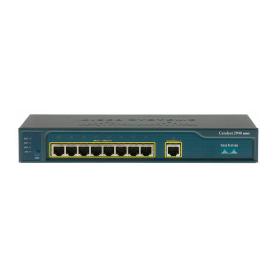
STA T DP LX SP D MO DE C at al y st 2 9 4 0 10 0B as e- SE RI ES SF P 10/100 Ethernet ports 100BASE-FX port SFP module slot Catalyst 2940 Switch Hardware Installation Guide OL-6157-01... -
Page 3: Port Numbering
(that is, the fastest line speed that both devices support and full-duplex transmission, if the attached device supports it) and configures itself accordingly. 10/100/1000 Port The 10/100/1000 port on the Catalyst 2940-8TT-S switch uses RJ-45 connectors and twisted-pair cabling. The port can connect to these devices: •... -
Page 4: 100Base-Fx Port
Appendix B, “Connectors and Cables.” The 10/100/1000 port on the Catalyst 2940-8TT-S switch can be explicitly set to operate at full- or half-duplex at 10 or 100 Mbps. The port is restricted to full-duplex mode when it is set at 1000 Mbps. -
Page 5: Sfp Modules
(copper) cable. This module can provide a Gigabit Ethernet connection of up to 100 meters through a Category 5 cable. Use only Cisco SFP modules on the Catalyst 2940-8TF-S switch. Each SFP module has an internal serial EEPROM that is encoded with security information. This encoding provides a way for Cisco to identify and validate that the SFP module meets the requirements for the switch. -
Page 6: Cable Guard
The Cisco CWDM SFPs operate on single-mode fiber. The SFPs support both Gigabit Ethernet as well as fiber channel (1 Gigabit and 2 Gigabit) links. For more information about Cisco CWDM SFPs, see the Cisco CWDM SFP Transceiver Compatibility Matrix at this URL: http://www.cisco.com/en/US/products/hw/modules/ps4999/products_device_support_table09186a00803bf095.html... - Page 7 Each port has a port status LED, also called a port LED. These LEDs display information about the individual ports. When you change the port mode, the meanings of the port LED colors change. Table 1-6 explains how to interpret these colors. Catalyst 2940 Switch Hardware Installation Guide OL-6157-01...
- Page 8 Port is operating at 100 Mbps. Flashing green Port is operating at 1000 Mbps. SFP modules Port is operating at 10 Mbps. Green Port is operating at 100 Mbps. Flashing green Port is operating at 1000 Mbps. Catalyst 2940 Switch Hardware Installation Guide OL-6157-01...
-
Page 9: Rear Panel Description
AC power connector to an AC power outlet. The switch accessory kit includes an L-shaped AC power cord. Table 1-7 lists the spare L-shaped AC power cords that you can order from your Cisco sales representative. Table 1-7 Spare L-Shaped Power Cords Type... -
Page 10: Console Port
You can connect a switch to a PC through the console port by using a RJ-45-to-DB-9 adapter cable. If you want to connect a switch to a terminal, you need to provide an RJ-45-to-DB-25 female DTE adapter. You can order a kit (part number ACS-DSBUASYN=) with that adapter from Cisco. For console-port and adapter-pinout information, see the “Cable and Adapter Specifications”... -
Page 11: Management Options
You can use Network Assistant to manage and monitor switch clusters or standalone devices. For more information, see the Getting Started with Cisco Network Assistant guide and the Network Assistant online help. - Page 12 Chapter 1 Overview Management Options Catalyst 2940 Switch Hardware Installation Guide 1-12 OL-6157-01...