Cisco Catalyst 3750G Getting Started Manual
Integrated wireless lan controller switch
Hide thumbs
Also See for Catalyst 3750G:
- Configuration manual (40 pages) ,
- Configuration manual (1204 pages)
Table of Contents
Advertisement
Catalyst 3750G Integrated Wireless LAN Controller Switch
Getting Started Guide
INCLUDING LICENSE AND WARRANTY
1
About this Guide
2
Taking Out What You Need
3
Running Express Setup
4
Managing the Switch
5
Preparing the Wireless LAN Controller for Operation
6
Planning Switch Stacks
7
Rack-Mounting
8
In Case of Difficulty
9
Obtaining Documentation
10
Documentation Feedback
Getting Started
Guide
Advertisement
Table of Contents
Troubleshooting

Related Manuals for Cisco Catalyst 3750G


Summary of Contents for Cisco Catalyst 3750G
- Page 1 Getting Started Guide Catalyst 3750G Integrated Wireless LAN Controller Switch Getting Started Guide INCLUDING LICENSE AND WARRANTY About this Guide Taking Out What You Need Running Express Setup Managing the Switch Preparing the Wireless LAN Controller for Operation Planning Switch Stacks...
-
Page 2: About This Guide
When using the online publications, refer to the documents that match the Cisco IOS software version running on the switch. The software version is on the Cisco IOS label on the switch rear panel. For translations of the warnings that appear in this publication, see the Regulatory Compliance and Safety Information for the Catalyst 3750 Switch that accompanies this guide. -
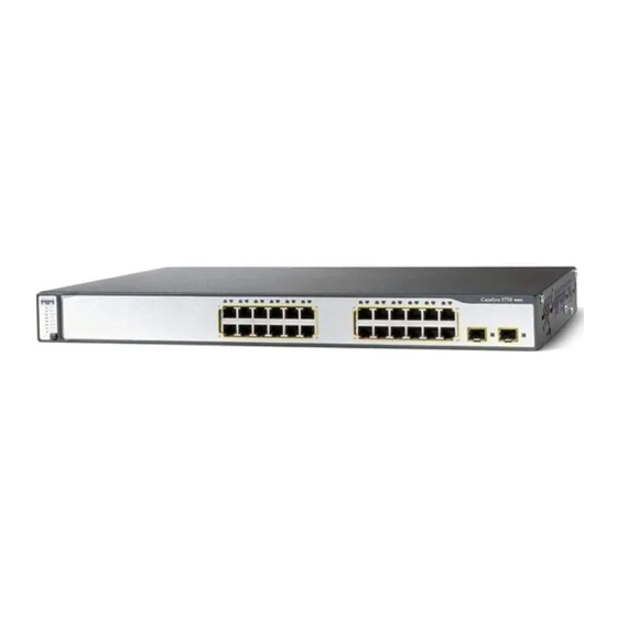
Page 3: Shipping Box Contents
375 0G ST ACK Wi rele ss SERI ES PoE -24 LA N Co ntro ller Catalyst 3750G Integrated Wireless LAN Controller switch Two 19-inch mounting brackets Four number-12 Phillips machine screws Four number-8 Phillips truss-head screws 0.5-meter, 1-meter or 3-meter... -
Page 4: Equipment That You Supply To Run Express Setup
POST. Verify that POST has completed by confirming that the SYST LED remains green. If the Step 4 switch fails POST, the SYST LED turns amber. POST errors are usually fatal. Call Cisco Systems immediately if your switch fails POST. - Page 5 Press and hold the Mode button for Step 5 3 seconds. When all of the LEDs above the Mode button turn green, release the Mode button. If the LEDs above the Mode button begin to blink after you press the SY ST button, release it.
- Page 6 The Express Setup page appears. If it does not appear, see the “In Case of Difficulty” Step 11 section on page 34 for help. Enter this information in the Network Settings fields: Step 12 • In the Management Interface (VLAN ID) field, the default is 1. Enter a new VLAN ID only if you want to change the management interface through which you manage the switch and to which you assign IP information.
- Page 7 In the Wireless Controller Settings area (see the Figure in Step 11), the stack number Step 13 displays the stack-member number of the switch. Enter this information: • In the Management Interface (VLAN ID) field, the default is 0. Enter a new VLAN ID only if you want to change the management interface through which you manage the controller and to which you assign IP information.
- Page 8 (Optional) You can enter the Optional Settings information now or enter it later by using Step 14 the device manager interface: • In the Host Name field, enter a name for the switch. The host name is limited to 31 characters; embedded spaces are not allowed. •...
-
Page 9: Managing The Switch
Downloading Cisco Network Assistant Cisco Network Assistant is a software program that you download from Cisco.com and run on your PC. It offers advanced options for configuring and monitoring multiple devices, including switches, switch clusters, switch stacks, routers, and access points. Network Assistant is free—there is no charge to download, install, or use it. -
Page 10: Command Line Interface
Refer to the Network Assistant online help and the getting started guide for more information. Command-Line Interface You can enter Cisco IOS commands and parameters through the CLI. Access the CLI either by connecting your PC directly to the switch console port or through a Telnet session from a remote PC or workstation. -
Page 11: Using The Configuration Wizard To Configure The Controller
Preparing the Wireless LAN Controller for Operation Follow these major steps to prepare the integrated wireless LAN controller for operation. • Using the Configuration Wizard to Configure the Controller • Logging into the Controller • Verifying Interface Settings and Port Operation •... - Page 12 Enter the management IP address of the switch (which you set in Step 12 of the Express Step 4 Setup) in the web browser, and press Enter. The Catalyst 3750 Device Manager page appears. Under Contents, click Controller Device Manager. Step 5 When prompted for a username and password, enter admin in each field.
- Page 13 In the System Name field, enter the system name, which is the name that you want to Step 7 assign to the controller. You can enter up to 32 ASCII characters. In the User Name and Password fields, enter the administrative username and password Step 8 for this controller.
- Page 14 Click Next. The Management Interface Configuration page appears. Step 12 Enter the VLAN identifier zero (0) if the VLAN ID set on the switch management interface Step 13 is 1. If you entered a VLAN ID other than 1 on the switch management interface (see Step 12 of the Running Express Setup section), enter the same VLAN ID for the controller.
- Page 15 Click Next. The Miscellaneous Configuration page appears. Step 15...
- Page 16 From the LWAPP Transport Mode drop-down box, choose Layer 3. The controller Step 16 operates only in Layer 3 mode. (Optional) In the RF Mobility Domain Name field, enter the name of the mobility group/ Step 17 RF group to which you want the controller to belong. Although the name that you enter here is assigned to both the mobility group and the RF group, these groups are not identical.
- Page 17 Enter the IP addresses of the primary and the optional secondary DHCP servers that Step 21 supply IP addresses to the controller AP-manager interface. If the AP-manager interface is on the same subnet as the management interface, the AP-manager interface uses the same DHCP server IP address as the management interface.
- Page 18 Click Next. The WLAN Policy Configuration page appears. Step 25 In the WLAN SSID field, enter the network name or service set identifier (SSID). This is Step 26 the default SSID that the access points use when they join a controller. Under General Policies, check the DHCP Address Assignment Required check box to Step 27 make clients request an IP address from a DHCP server, or uncheck this check box to allow...
- Page 19 Click Next. The RADIUS Server Configuration page appears. Step 29 To configure a RADIUS server now, enter the IP address, the shared secret, and the Step 30 communication port of the RADIUS server, and click Apply. Otherwise, click Skip. The IEEE 802.11 Configuration page appears.
-
Page 20: Logging Into The Controller
Check or uncheck the Auto RF check box to enable or disable the controller radio resource Step 32 management (RRM) auto-RF feature. The auto-RF feature enables the controller to automatically form an RF group with other controllers. The group dynamically elects a leader to optimize RRM parameter settings, such as channel and send power assignments, for the group. -
Page 21: Verifying Interface Settings And Port Operation
Link aggregation (LAG) is always enabled for the integrated wireless LAN controller and cannot be disabled. LAG bundles all of the controller distribution system ports into a single IEEE 802.3ad port channel. See the Cisco Wireless LAN Controller Configuration Guide 4.0 or later for more information. -
Page 22: Connecting Access Points
For the integrated wireless LAN controller, access points can operate only in Layer 3 Lightweight Access Point Protocol (LWAPP) mode. You have prepared the controller for basic operation. See the Cisco Wireless LAN Controller Configuration Guide, Release 4.0 or later, for information on configuring the controller to meet the... -
Page 23: Powering Considerations
If you do not specify the length of the StackWise cable, the 0.5-meter cable is supplied. If you require the 1-meter cable or 3-meter cable, you can order it from your Cisco supplier. For cable numbers, see the Catalyst 3750 Switch Hardware Installation Guide. -
Page 24: Cabling Considerations
These illustrations show the recommended Catalyst 3750 switch stack configurations with redundant StackWise cabling connections for optimized stack bandwidth. For more configuration examples, see the Catalyst 3750 Switch Hardware Installation Guide on Cisco.com. Vertical Stacking In this example, the stack uses the 0.5-meter StackWise cable to make redundant connections. -
Page 25: Side-By-Side Stacking
Rack-Mounting This section covers basic 19-inch rack-mounting and switch port connections. For additional cabling information, see the Catalyst 3750 Switch Hardware Installation Guide on Cisco.com. Equipment That You Supply You need to supply a number-2 Phillips screwdriver to rack-mount the switch. -
Page 26: Before You Begin
Before You Begin When determining where to install the switch, verify that these guidelines are met: • Airflow around the switch and through the • Cabling is away from sources of electrical vents is unrestricted. noise, such as radios, power lines, and fluorescent lighting fixtures. -
Page 27: Installation Warning Statements
This section includes the basic installation warning statements. Translations of these warning statements appear in the Regulatory Compliance and Safety Information for the Catalyst 3750 Switch document that shipped with the switch and is also available on Cisco.com. Warning Only trained and qualified personnel should be allowed to install, replace, or service this equipment. - Page 28 Warning This equipment must be grounded. Never defeat the ground conductor or operate the equipment in the absence of a suitably installed ground conductor. Contact the appropriate electrical inspection authority or an electrician if you are uncertain that suitable grounding is available. Statement 1024 Warning If a redundant power system (RPS) is not connected to the switch, install an RPS connector cover on the back of the switch.
-
Page 29: Attaching The Brackets
Attaching the Brackets Use four Phillips flat-head screws to attach the long side of the brackets to wireless controller LAN switches in one of three mounting positions. SYS T MAS TR ST A T DUP LX Ca tal yst SPE ED 37 50 G ST ACK Wi rel ess... -
Page 30: Rack-Mount The Switch
Rack-Mount the Switch Use the black Phillips machine screw to attach the cable guide to the left or right bracket. Use the four number-12 Phillips machine screws to attach the brackets to the rack. Cable guide SYS T MAS TR ST A T DUP LX Ca tal yst... -
Page 31: Connect The Stackwise Cables
Insert the other end of the cable into the connector of the other switch, and secure the screws tightly. Caution Removing and inserting the StackWise cable can shorten its useful life. Do not remove and insert the cable more often than is absolutely necessary. Always use a Cisco-approved StackWise cable to connect the switches. Note... -
Page 32: Connect To The Switch Ports
The automatic medium-dependent interface crossover (auto-MDIX) feature is enabled by Note default on switches running Cisco IOS Release 12.2(18)SE or later. When the auto-MDIX feature is enabled, the switch detects the required cable type for copper Ethernet connections and configures the interfaces accordingly. Therefore, you can use either a crossover or a straight-through cable for connections to a copper 10/100, 10/100/1000, or 1000BASE-T SFP module port on the switch, regardless of the type of device on the other end of the connection. -
Page 33: Install The Sfp Modules And Connect To The Ports
14 X 24 X SFP module port For a list of supported modules, see the release notes on Cisco.com. For detailed instructions on installing, removing, and connecting to SFP modules, see the documentation that came with the SFP module. Removing and inserting an SFP module can shorten its useful life. Do not remove and Caution insert SFP modules more often than is absolutely necessary. -
Page 34: In Case Of Difficulty
In Case of Difficulty If you experience difficulty, help is available in this section and also on Cisco.com. This section includes Express Setup troubleshooting, how to reset the switch, how to access help online, and where to find more information. -
Page 35: Resetting The Switch
• Did you wait 30 seconds after you connected If not, wait 30 seconds, re-enter 10.0.0.1 in the the switch and the PC before you entered the browser, and press Enter. IP address in your browser? • Did you enter the wrong address in the If yes, re-enter 10.0.0.1 in the browser, and press browser, or is there an error message? Enter. -
Page 36: Troubleshooting The Wireless Controller
You can troubleshoot the controller by using the show platform wireless-controller privileged EXEC command. It displays information about the internal wireless controller in a Catalyst 3750G Integrated Wireless LAN Controller Switch. You can use it to determine the stack number of a switch or switches in the stack that contain the integrated wireless LAN controller. -
Page 37: Obtaining Documentation
• Release Notes for the Catalyst 3750 Switch (not orderable but available on Cisco.com) Release Notes for the Catalyst 3750G Integrated Wireless LAN Controller Switch (not orderable but • available on Cisco.com) • Catalyst 3750 Switch Software Configuration Guide ( not orderable but available on Cisco.com ). -
Page 38: Product Documentation Dvd
The DVD enables you to access multiple versions of installation, configuration, and command guides for Cisco hardware and software products. With the DVD, you have access to the same HTML documentation that is found on the Cisco website without being connected to the Internet. -
Page 39: Documentation Feedback
You can rate and provide feedback about Cisco technical documents by completing the online feedback form that appears with the technical documents on Cisco.com. You can submit comments about Cisco documentation by using the response card (if present) behind the front cover of your document or by writing to the following address:... -
Page 40: Reporting Security Problems In Cisco Products
Technical Support & Documentation website on Cisco.com features extensive online support resources. In addition, if you have a valid Cisco service contract, Cisco Technical Assistance Center (TAC) engineers provide telephone support. If you do not have a valid Cisco service contract, contact your reseller. -
Page 41: Cisco Technical Support & Documentation Website
Cisco engineer. The TAC Service Request Tool is located at this URL: http://www.cisco.com/techsupport/servicerequest For S1 or S2 service requests, or if you do not have Internet access, contact the Cisco TAC by telephone. (S1 or S2 service requests are those in which your network is down or severely degraded.) Cisco engineers are assigned immediately to S1 and S2 service requests to help keep your business operations running smoothly. -
Page 42: Definitions Of Service Request Severity
Cisco products that are sold through channel partners. It is updated twice a year and includes the latest Cisco offerings. To order and find out more about the Cisco Product Quick Reference Guide, go to this URL: http://www.cisco.com/go/guide... - Page 43 URL: http://www.cisco.com/packet • iQ Magazine is the quarterly publication from Cisco Systems designed to help growing companies learn how they can use technology to increase revenue, streamline their business, and expand services. The publication identifies the challenges facing these companies and the technologies to help solve them, using real-world case studies and business strategies to help readers make sound technology investment decisions.
-
Page 44: Cisco Limited Lifetime Hardware Warranty Terms
Your formal Warranty Statement, including the warranties and license agreements applicable to Cisco software, is available on Cisco.com. Follow these steps to access and download the Cisco Information Packet and your warranty and license agreements from Cisco.com. - Page 45 Duration of Hardware Warranty A Cisco product hardware warranty is supported for as long as the original end user continues to own or use the product, provided that the fan and power supply warranty is limited to five (5) years. In the event of a discontinuance of product manufacture, the Cisco warranty support is limited to five (5) years from the announcement of the discontinuance.
- Page 48 Slovakia • Slovenia • South Africa • Spain • Sweden • Switzerland • Taiwan • Thailand • Turkey • Ukraine • United Kingdom • United States • Venezuela • Vietnam • Zimbabwe CCVP, the Cisco logo, and Welcome to the Human Network are trademarks of Cisco Systems, Inc.; Changing the Way We Work, Live, Play, and Learn is a service mark of Cisco Systems, Inc.;...