Cisco Catalyst 2960 Hardware Installation Manual
Hide thumbs
Also See for Catalyst 2960:
- Configuration manual (2288 pages) ,
- Software configuration manual (980 pages) ,
- Command reference manual (800 pages)
Table of Contents
Advertisement
Quick Links
Catalyst 2960 Switch Hardware
Installation Guide
February 2008
THE SPECIFICATIONS AND INFORMATION REGARDING THE PRODUCTS IN THIS MANUAL ARE SUBJECT TO
CHANGE WITHOUT NOTICE. ALL STATEMENTS, INFORMATION, AND RECOMMENDATIONS IN THIS
MANUAL ARE BELIEVED TO BE ACCURATE BUT ARE PRESENTED WITHOUT WARRANTY OF ANY KIND,
EXPRESS OR IMPLIED. USERS MUST TAKE FULL RESPONSIBILITY FOR THEIR APPLICATION OF ANY
PRODUCTS.
Americas Headquarters
Cisco Systems, Inc.
170 West Tasman Drive
San Jose, CA 95134-1706
USA
http://www.cisco.com
Tel: 408 526-4000
800 553-NETS (6387)
Fax: 408 527-0883
Text Part Number: OL-7075-05
Advertisement
Table of Contents

Related Manuals for Cisco Catalyst 2960


Summary of Contents for Cisco Catalyst 2960
- Page 1 Catalyst 2960 Switch Hardware Installation Guide February 2008 THE SPECIFICATIONS AND INFORMATION REGARDING THE PRODUCTS IN THIS MANUAL ARE SUBJECT TO CHANGE WITHOUT NOTICE. ALL STATEMENTS, INFORMATION, AND RECOMMENDATIONS IN THIS MANUAL ARE BELIEVED TO BE ACCURATE BUT ARE PRESENTED WITHOUT WARRANTY OF ANY KIND, EXPRESS OR IMPLIED.
- Page 2 OR ITS SUPPLIERS HAVE BEEN ADVISED OF THE POSSIBILITY OF SUCH DAMAGES. CCVP, the Cisco logo, and Welcome to the Human Network are trademarks of Cisco Systems, Inc.; Changing the Way We Work, Live, Play, and Learn is a service mark of Cisco Systems, Inc.;...
-
Page 3: Table Of Contents
System LED 1-13 RPS LED 1-13 Port LEDs and Modes 1-14 Dual-Purpose Port LEDs 1-17 Cable Guard for the Catalyst 2960-8TC-L, 2960G-8TC-L, and 2960PD-8TT-L Switches 1-17 Rear Panel Description 1-17 Power Supplies 1-18 Internal Power Supply Connector 1-18 Cisco RPS Connectors... - Page 4 Guidelines for Particulate Matter Installation Guidelines Verifying Package Contents Verifying Switch Operation Installing the Switch Rack-Mounting Removing Screws from the Switch Attaching Brackets to the Catalyst 2960 Switch Mounting the Switch in a Rack 2-11 Attaching the Cable Guide 2-12 Wall-Mounting 2-12...
- Page 5 Connector and Cable Specifications A P P E N D I X Connector Specifications 10/100/1000 Ports Connecting to 10BASE-T- and 100BASE-TX-Compatible Devices Connecting to 1000BASE-T Devices SFP Module Ports Dual-Purpose Ports Console Port Catalyst 2960 Switch Hardware Installation Guide OL-7075-05...
- Page 6 Accessing the CLI Through the Console Port Connecting to the Console Port Starting the Terminal Emulation Software Connecting to a Power Source Entering the Initial Configuration Information IP Settings Completing the Setup Program N D E X Catalyst 2960 Switch Hardware Installation Guide OL-7075-05...
- Page 7 This guide is for the networking or computer technician responsible for installing the Catalyst 2960 switch, hereafter known as the switch. We assume that you are familiar with the concepts and terminology of Ethernet and local area networking. If you are interested in more training and education in these areas, learning opportunities including training courses, self-study options, seminars, and career certifications programs are available on the Cisco Training &...
-
Page 8: Related Documentation
SAVE THESE INSTRUCTIONS The safety warnings for this product are translated into several languages in the Regulatory Compliance and Safety Information for the Catalyst 2960 Switch that ships with the product. The EMC regulatory statements are also included in that guide. - Page 9 For information on obtaining documentation, obtaining support, providing documentation feedback, security guidelines, and also recommended aliases and general Cisco documents, see the monthly What's New in Cisco Product Documentation, which also lists all new and revised Cisco technical documentation, at this URL: http://www.cisco.com/en/US/docs/general/whatsnew/whatsnew.html...
- Page 10 Preface Catalyst 2960 Switch Hardware Installation Guide OL-7075-05...
-
Page 11: Chapter 1 Product Overview
C H A P T E R Product Overview The Catalyst 2960 switch—also referred to as the switch—is an Ethernet switch to which you can connect devices such as workstations, Cisco Wireless Access Points, Cisco IP Phones, and other network devices including servers, routers, and other switches. - Page 12 44 10/100/1000BASE-T Ethernet ports and 4 dual-purpose ports The Catalyst 2960-8TC-L, Catalyst 2960G-8TC-L, and Catalyst 2960PD-8TT-L switches are smaller than the other Catalyst 2960 switches. They can be mounted with a magnet, have security lock slots, and do not have a fan. See Chapter 3, “Switch Installation (8-Port Switches),”...
-
Page 13: Front Panel Description
Some Catalyst 2960 switches have a redundant power system (RPS) connector for an optional Cisco RPS 2300 or Cisco RPS 675 redundant power system that operates on AC input and supplies backup DC power to the switch. See the compatibility matrix documents for the RPS systems on Cisco.com for more information about switch support for the RPS models. -
Page 14: Catalyst 2960-24-S, 2960-24Tc-S, And 2960-48Tc-S Switches
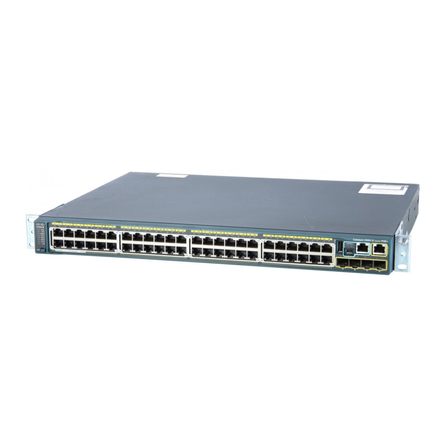
Catalyst 2960-24-S, 2960-24TC-S, and 2960-48TC-S Switches The 10/100 ports on the Catalyst 2960-24-S switch are numbered as follows: The first member of the pair (port 1) is above the second member (port 2), port 3 is above port 4, and so on. See Figure 1-1. -
Page 15: 2960-48Tt-L Switches
10/100 PoE ports 2 Dual-purpose ports The Catalyst 2960-24TC-L and Catalyst 2960-48TC-L switches have dual-purpose ports, that is, 10/100/1000 ports 1 and 2 can use either the SFP module or the RJ-45 connector for that port, but not both. Use the software to set the connector type for these ports. For more information about the dual-purpose port, see the “Dual-Purpose Port”... -
Page 16: Catalyst 2960G-24Tc-L And Catalyst 2960G-48Tc-L Switches
Chapter 1 Product Overview Front Panel Description The Catalyst 2960-24LT-L, Catalyst 2960-24TT-L, and Catalyst 2960-48TT-L switches have two 10/100/1000 uplink ports, numbered 1 and 2. Ports 1 to 8 on the Catalyst 2960-24LT-L switch are PoE ports. See Figure 1-7,... -
Page 17: Catalyst 2960 Switch 8-Port Switches
Figure 1-11 Catalyst 2960G-48TC-L Switch Front Panel 10/100/1000 ports 2 Dual-purpose ports Catalyst 2960 Switch 8-Port Switches These sections describe the Catalyst 2960 8-port switches: • Catalyst 2960PD-8TT-L Switch, page 1-7 Catalyst 2960-8TC-L Catalyst 2960G-8TC -L Switches, page 1-8 •... -
Page 18: Catalyst 2960-8Tc-L Catalyst 2960G-8Tc -L Switches
100BASE-TX traffic requires a Category 5 or higher cable. 10BASE-T traffic can use Category 3 or Category 4 cables. When you connect the switch to workstations, servers, routers, and Cisco IP Phones, be sure that the cable is a straight-through cable. When you connect the switch to switches or hubs, use a crossover cable. -
Page 19: 10/100/1000 Ports
Statement 1072 The 10/100 ports on the Catalyst 2960-24PC-L and ports 1 to 8 of the 10/100 ports on the Catalyst 2960-24LT-L switches provide PoE support for devices that are compliant with IEEE 802.3af. -
Page 20: Sfp Module Slots
The Auto setting is the default. However, when you select the Never setting, the port does not provide power even if a Cisco IP phone or an access point is connected to it. Cisco enhanced power negotiation allows some powered devices, such as the Cisco 7970G IP Phone, to operate in high-power mode on Catalyst 2960 PoE switches. -
Page 21: Dual-Purpose Port
IEEE 802.3af). (See Figure 1-15.) Through an external AC power adapter that connects to the back of the switch. This external power adapter (PWR-A=) is not included with the switch, but you can order it from your Cisco representative. (See Figure 1-16.) -
Page 22: Leds
The switch software configuration guide describes how to use the CLI to configure and to monitor individual switches and switch clusters. The Catalyst 2960-24PC-L and Catalyst 2960-24LT-L switches have a PoE LED. The Catalyst 2960-8TC-L, 2960G-8TC-L, 2960PD-8TT-L, 2960-24-S, 2960-24TC-S, and 2960-48TC-S switches do not have an RPS LED. -
Page 23: System Led
The RPS LED shows the RPS status. Table 1-3 lists the LED colors and their meanings. Note The Catalyst 2960-8TC-L, 2960G-8TC-L, 2960PD-8TT-L, 2960-24-S, 2960-24TC-S, and 2960-48TC-S switches do not have an RPS LED. Catalyst 2960 Switch Hardware Installation Guide 1-13... -
Page 24: Port Leds And Modes
The internal power supply in a switch has failed, and the RPS is providing power to the switch (redundancy has been allocated to this device). For more information about the Cisco RPS 2300 or the Cisco RPS 675, see the related hardware installation guide for that power system. - Page 25 Even if PoE mode is not selected, the PoE LED still shows PoE problems when they are detected. Table 1-6 lists the PoE mode LED colors and their meanings. The PoE LED applies only to Catalyst 2960 switches that support PoE.
- Page 26 PoE faults are caused when noncompliant cabling or powered devices are connected to a PoE port. Use only standard-compliant cabling to connect Cisco pre-standard IP Phones or wireless access points or IEEE 802.3af-compliant devices to PoE ports. You must remove from the network the cable or device that causes a PoE fault.
-
Page 27: Dual-Purpose Port Leds
CBLGRD-C2960G-8TC: Cisco Catalyst 2960G-8TC switch Rear Panel Description The rear panels on the Catalyst 2960 switches have all or some of these features: an RJ-45 console port, a fan exhaust, an RPS connector, and an AC power connector (see Figure 1-19.) These are the... -
Page 28: Power Supplies
Note 2960PD-8TT-L, 2960-24-S, 2960-24TC-S, and 2960-48TC-S switches. Connect the switch and the Cisco RPS 2300 or the Cisco RPS 675 to the same AC power source. See the Cisco redundant power systems (RPS) compatibility matrix documents on Cisco.com for more information about which RPS are supported on each of the Catalyst 2960 switches. -
Page 29: Cisco Rps 2300 Connector
It automatically senses when the power supply of a connected switch fails and provides power to the failed switch, preventing loss of network traffic. The Cisco RPS 2300 has two output levels: –52 V and 12 V. The total maximum output power depends on the installed power-supply modules. -
Page 30: Security Slots
Management Options Security Slots The Catalyst 2960-8TC-L, 2960G-8TC-L, and 2960PD-8TT-L switches have security slots on the left and right side panels. You can install an optional cable lock, such as the type that is used to secure a laptop computer, to secure either or both sides of the switch. -
Page 31: Network Configurations
You can fully configure and monitor the switch and switch cluster members from the CLI. You can access the CLI either by connecting your management station directly to the switch console port or by using Telnet from a remote management station. See the Catalyst 2960 Switch Command Reference on Cisco.com for more information. - Page 32 Chapter 1 Product Overview Management Options Catalyst 2960 Switch Hardware Installation Guide 1-22 OL-7075-05...
-
Page 33: Switch Installation (24- And 48-Port Switches)
Chapter 3, “Switch Installation (8-Port Switches).” The instructions in this chapter for connecting to the switch ports and for installing and connecting to the small form-factor pluggable (SFP) modules apply to all Catalyst 2960 switches, including the 8-port switches. Read the topics and perform the procedures in this order: •... -
Page 34: C H A P T E R 2 Switch Installation (24- And 48-Port Switches)
These warnings are translated into several languages in the Regulatory Compliance and Safety Information for the Catalyst 2960 Switch document that ships with the switch. To prevent the switch from overheating, do not operate it in an area that exceeds the maximum Warning recommended ambient temperature of 113°F (45°C). -
Page 35: Statement 371-Power Cable And Ac Adapter
This equipment must be grounded. Never defeat the ground conductor or operate the equipment in the Warning absence of a suitably installed ground conductor. Contact the appropriate electrical inspection authority or an electrician if you are uncertain that suitable grounding is available. Statement 1024 Catalyst 2960 Switch Hardware Installation Guide OL-7075-05... -
Page 36: Guidelines For Particulate Matter
Warning Guidelines for Particulate Matter Cisco Ethernet Switches are equipped with cooling mechanisms, such as fans and blowers. However, these fans and blowers can draw dust and other particles, causing contaminant buildup inside the chassis, which can result in a system malfunction. -
Page 37: Installation Guidelines
• International Electrotechnical Commission (IEC) IP-20 • This precaution applies to all Catalyst 2960 switches except for the Catalyst 2960-8TC, 2960G-8TC, and 2960PD-8TT-L switches. Installation Guidelines This section does not apply to the Catalyst 2960-8TC, 2960G-8TC, and 2960PD-8TT-L switches. For information applicable to those switches, see Chapter 3, “Switch Installation (8-Port Switches).”... -
Page 38: Verifying Package Contents
Switch Installation (24- and 48-Port Switches) Preparing for Installation Verifying Package Contents This section does not apply to the Catalyst 2960-8TC, 2960G-8TC, and 2960PD-8TT-L switches. For information applicable to those switches, see Chapter 3, “Switch Installation (8-Port Switches).” Carefully remove the contents from the shipping container, and look at each item for damage. If any item is missing or damaged, contact your Cisco representative or reseller for support. -
Page 39: Verifying Switch Operation
If a switch fails POST, the System LED turns amber. POST failures are usually fatal. Call Cisco technical support representative if your switch fails POST. After a successful POST, disconnect the power cord from the switch. Install the switch in a rack, on a wall, on a table, or on a shelf as described in the “Installing the Switch”... -
Page 40: Rack-Mounting
An optional bracket kit that is not included with the switch is required to install the switch in a 24-inch rack. You can order a kit that contains the 24-inch rack-mounting brackets and hardware from Cisco by using part number RCKMNT-1RU=. - Page 41 Follow the same steps to attach the second bracket to the opposite side. Figure 2-2 Attaching Brackets for 19-Inch Racks to a Catalyst 2960 Switch, Front Panel Forward S Y S T R P S...
- Page 42 Switch Installation (24- and 48-Port Switches) Installing the Switch Figure 2-5 Attaching Brackets for 24-Inch Racks to a Catalyst 2960 Switch, Rear Panel Forward Phillips flat-head screws Figure 2-6 Attaching Brackets for 19-Inch Telco Racks to a Catalyst 2960 Switch...
- Page 43 Power on the switch. See the “Verifying Switch Operation” section on page 2-7. • Connect to a 10/100 or 10/100/1000 port, and run Express Setup. See the Catalyst 2960 Switch • Getting Started Guide for instructions. Connect to the front-panel ports. See the “Connecting to the 10/100 and 10/100/1000 Ports”...
-
Page 44: Attaching The Cable Guide
MOD E Cable guide screw Wall-Mounting This section does not apply to the Catalyst 2960-8TC, 2960G-8TC, and 2960PD-8TT-L switches. For information applicable to those switches, see Chapter 3, “Switch Installation (8-Port Switches).” To install the switch on a wall, follow the instructions in these sections: •... -
Page 45: Attaching The Brackets To The Switch For Wall-Mounting
If an RPS is not connected to the switch, install an RPS connector cover on the back of the switch. Warning Statement 265 Figure 2-11 Attaching the RPS Connector Cover on the Catalyst 2960 Switch CO NS OL Phillips pan-head screws RPS connector... -
Page 46: Mounting The Switch On A Wall
If a redundant power system (RPS) is not connected to the switch, install an RPS connector cover on the back of the switch. Statement 265 Figure 2-12 Mounting the Switch on a Wall User-supplied screws Catalyst 2960 Switch Hardware Installation Guide 2-14 OL-7075-05... -
Page 47: Table- Or Shelf-Mounting
You can use any combination of SFP modules. Refer to the Catalyst 2960 switch release notes for the list of SFP modules that the Catalyst 2960 switch supports. Each SFP module must be of the same type as the SFP module on the other end of the cable, and the cable must not exceed the stipulated cable length for reliable communications. -
Page 48: Installing Sfp Modules Into Sfp Module Slots
Installing and Removing SFP Modules stipulations for SFP module connections. Use only Cisco SFP modules on the Catalyst 2960 switch. Cisco SFP modules and the Catalyst 2960 switch support the Quality ID feature. Only SFP modules with the Quality ID feature are supported. -
Page 49: Removing Sfp Modules From Sfp Module Slots
If the module has a bale-clasp latch, pull the bale out and down to eject the module. If the bale-clasp latch is obstructed and you cannot use your index finger to open it, use a small, flat-blade screwdriver or other long, narrow instrument to open the bale-clasp latch. Catalyst 2960 Switch Hardware Installation Guide 2-17 OL-7075-05... -
Page 50: Connecting To The 10/100 And 10/100/1000 Ports
To prevent electrostatic-discharge (ESD) damage, follow your normal board and component handling Caution procedures. When connecting to workstations, servers, routers, and Cisco IP Phones, connect a straight-through Step 1 cable to an RJ-45 connector on the front panel. (See Figure 2-16.) When connecting to switches or... -
Page 51: Connecting To Sfp Modules
For instructions about how to install or remove an SFP module, see the “Installing and Removing SFP Modules” section on page 2-15. For instructions on how to connect to a dual-purpose port, see the “Connecting to a Dual-Purpose Port” section on page 2-22. Catalyst 2960 Switch Hardware Installation Guide 2-19 OL-7075-05... -
Page 52: Connecting To Fiber-Optic Sfp Modules
If the LED is off, the target device might not be turned on, there might be a cable problem, or there might be problem with the adapter installed in the target device. See Chapter 4, “Troubleshooting,” solutions to cabling problems. If necessary, reconfigure and restart the switch or target device. Step 5 Catalyst 2960 Switch Hardware Installation Guide 2-20 OL-7075-05... -
Page 53: Connecting To 1000Base-T Sfp Modules
If the LED is off, the target device might not be turned on, there might be a cable problem, or there might be problem with the adapter installed in the target device. See Chapter 4, “Troubleshooting,” solutions to cabling problems. If necessary, reconfigure and restart the switch or target device. Step 4 Catalyst 2960 Switch Hardware Installation Guide 2-21 OL-7075-05... -
Page 54: Connecting To A Dual-Purpose Port
• Start the Network Assistant application, which is described in the Getting Started with Cisco Network Assistant guide. Through this GUI, you can configure and monitor a switch cluster or an individual switch. - Page 55 Use the CLI from the console to configure the switch as a member of a cluster or as an individual switch. See the Catalyst 2960 Switch Software Configuration Guide and the Catalyst 2960 Switch Command Reference on Cisco.com for information on using the CLI with a Catalyst 2960 switch. •...
- Page 56 Chapter 2 Switch Installation (24- and 48-Port Switches) Where to Go Next Catalyst 2960 Switch Hardware Installation Guide 2-24 OL-7075-05...
- Page 57 It also describes how to install the switch. The installation information in this chapter is specific to the Catalyst 2960-8TC-L, Catalyst 2960G-8TC-L, and Catalyst 2960PD-8TT-L switches. For installation information applicable to the other Catalyst 2960 switches, see Chapter 2, “Switch Installation (24- and 48-Port Switches).”...
-
Page 58: Preparing For Installation
• If the rack is provided with stabilizing devices, install the stabilizers before mounting Statement 1006 or servicing the unit in the rack. Catalyst 2960 Switch Hardware Installation Guide OL-7075-05... -
Page 59: Installation Guidelines
Installation of the equipment must comply with local and national electrical codes. Statement 1074 Warning Installation Guidelines This section is specific to the Catalyst 2960 8-port switches. For information applicable to the other Catalyst 2960 switches, see Chapter 2, “Switch Installation (24- and 48-Port Switches).”... -
Page 60: Equipment That You Supply
1000BASE-ZX SFP module at each end of the link. Equipment That You Supply This section is specific to the Catalyst 2960 8-port switches. For information applicable to the other Catalyst 2960 switches, see Chapter 2, “Switch Installation (24- and 48-Port Switches).”... -
Page 61: Verifying Package Contents
Installing the Catalyst 2960 8-port switches in a 19-inch rack requires an optional bracket kit that is not included with the switch. You can order a kit containing the 19-inch rack-mounting brackets and hardware from Cisco. -
Page 62: Verifying Switch Operation
“Installing the Switch” section on page 3-6. Installing the Switch This section is specific to the Catalyst 2960 8-port switches. For information applicable to the other Catalyst 2960 switches, see Chapter 2, “Switch Installation (24- and 48-Port Switches).” This section describes these installation procedures: Desk- or Shelf-Mounting (without Mounting Screws), page 3-6 •... -
Page 63: Desk- Or Shelf-Mounting (With Mounting Screws)
Appendix C, “Configuring the Switch with the CLI-Based Setup Program.” Desk- or Shelf-Mounting (with Mounting Screws) This section is specific to the Catalyst 2960 8-port switches. For information applicable to the other Catalyst 2960 switches, see Chapter 2, “Switch Installation (24- and 48-Port Switches).”... - Page 64 Do not stack switches or place switches side-by-side unless they are separated on all sides with at least 3 inches (7.6 cm) of clearance from each other. Do not place any items on the top of the switch. Catalyst 2960 Switch Hardware Installation Guide OL-7075-05...
-
Page 65: Under The Desk- Or Shelf-Mounting (With Mounting Screws)
Switch with the CLI-Based Setup Program.” Under the Desk- or Shelf-Mounting (with Mounting Screws) This section is specific to the Catalyst 2960 8-port switches. For information applicable to the other Catalyst 2960 switches, see Chapter 2, “Switch Installation (24- and 48-Port Switches).”... - Page 66 Place the switch onto the mounting screws, and slide the switch forward until it locks in place, as shown Step 7 Figure 3-4. We strongly recommend that you allow at least 3 inches (7.6 cm) of clearance around the Note ventilation openings to prevent airflow restriction and overheating. Catalyst 2960 Switch Hardware Installation Guide 3-10 OL-7075-05...
- Page 67 “Connecting to a Dual-Purpose Port” section on page 2-22 to complete the installation. For configuration instructions about using the CLI setup program, go to Appendix C, “Configuring the Switch with the CLI-Based Setup Program.” Catalyst 2960 Switch Hardware Installation Guide 3-11 OL-7075-05...
-
Page 68: Wall-Mounting (With Mounting Screws)
Switch Installation (8-Port Switches) Installing the Switch Wall-Mounting (with Mounting Screws) This section is specific to the Catalyst 2960 8-port switches. For information applicable to the other Catalyst 2960 switches, see Chapter 2, “Switch Installation (24- and 48-Port Switches).” The steps in this section show how to mount the switch with the front panel facing down (as shown in... - Page 69 Power on the switch. See the “Verifying Switch Operation” section on page 3-6. Connect to a 10/100 or 10/100/1000 port, and run Express Setup. See the switch getting started guide for instructions. Catalyst 2960 Switch Hardware Installation Guide 3-13 OL-7075-05...
-
Page 70: Magnet Mounting
Appendix C, “Configuring the Switch with the CLI-Based Setup Program.” Magnet Mounting This section is specific to the Catalyst 2960 8-port switches. For information applicable to the other Catalyst 2960 switches, see Chapter 2, “Switch Installation (24- and 48-Port Switches).”... -
Page 71: Rack-Mounting
Chapter 2, “Switch Installation (24- and 48-Port Switches).” Installing the Catalyst 2960 8-port switches in a 19-inch rack requires an optional bracket kit that is not included with the switch. You can order a kit containing the 19-inch rack-mounting brackets and hardware from Cisco. -
Page 72: Mounting The Switch In A 19-Inch Rack
Switch with the CLI-Based Setup Program.” Wall-Mounting (with Rack-Mount Brackets) To install the Catalyst 2960 8-port switches in a 19-inch rack requires an optional bracket kit that is not included with the switch. You can order a kit containing the 19-inch rack-mounting brackets and hardware from Cisco. - Page 73 “Connecting to a Dual-Purpose Port” section on page 2-22 to complete the installation. For configuration instructions about using the CLI setup program, go to Appendix C, “Configuring the Switch with the CLI-Based Setup Program.” Catalyst 2960 Switch Hardware Installation Guide 3-17 OL-7075-05...
-
Page 74: Where To Go Next
• switch. See the Catalyst 2960 Switch Software Configuration Guide and the Catalyst 2960 Switch Command Reference on Cisco.com for information on using the CLI with a Catalyst 2960 switch. Start an SNMP application such as the CiscoView application. •... -
Page 75: Chapter 4 Troubleshooting
You can also get statistics from the browser interface, from the command-line interface (CLI), or from a Simple Network Management Protocol (SNMP) workstation. See the software configuration guide, the switch command reference guide on Cisco.com, or the documentation that came with your SNMP application for details. -
Page 76: Verify Switch Post Results
LED blinks amber. If POST fails, the system LED remains amber. If POST completes successfully, the system LED rapidly blinks green. POST failures are usually fatal. Contact your Cisco technical support representative if your switch does Note not pass POST. -
Page 77: Ethernet And Fiber Cables
Transceiver Module Port Issues Use only Cisco small form-factor (SFP) modules on the switch. Each Cisco module has an internal serial EEPROM that is encoded with security information. This encoding provides a way for Cisco to identify and validate that the module meets the requirements for the switch. -
Page 78: Ping The End Device
A manually set speed or duplex parameter is different from the manually set speed or duplex • parameter on the connected port. A port is set to autonegotiate, and the connected port is set to full duplex with no autonegotiation. • Catalyst 2960 Switch Hardware Installation Guide OL-7075-05... -
Page 79: Autonegotiation And Nic Cards
Setup as described in the switch getting started guide that is included with the switch. You can also configure the switch by using the CLI setup procedure described in Appendix C, “Configuring the Switch with the CLI-Based Setup Program.” Catalyst 2960 Switch Hardware Installation Guide OL-7075-05... -
Page 80: Locating The Switch Serial Number
Chapter 4 Troubleshooting Locating the Switch Serial Number Locating the Switch Serial Number If you contact Cisco Technical Assistance, you need to know the serial number of your switch. See Figure 4-1 through Figure 4-3 to locate the serial number on your switch. You can also use the show version command to get the serial number. - Page 81 Chapter 4 Troubleshooting Locating the Switch Serial Number Figure 4-3 Serial Number Location on the Catalyst 2960-8TC-L, Catalyst 2960G-8TC-L, and Catalyst 2960PD-8TT-L Switches SN: XXXNNNNXXXX Catalyst 2960 Switch Hardware Installation Guide OL-7075-05...
- Page 82 Chapter 4 Troubleshooting Locating the Switch Serial Number Catalyst 2960 Switch Hardware Installation Guide OL-7075-05...
-
Page 83: Appendix
A P P E N D I X Connector and Cable Specifications This appendix describes the Catalyst 2960 switch ports and the cables and adapters that you use to connect the switch to other devices and includes these sections: Connector Specifications, page A-1 •... -
Page 84: Connecting To 1000Base-T Devices
X or when both ports do not have an X. Figure A-1 10/100/1000 Port Pinouts Label 4 5 6 7 8 TP0+ TP0- TP1+ TP2+ TP2- TP1- TP3+ TP3- Catalyst 2960 Switch Hardware Installation Guide OL-7075-05... -
Page 85: A P P E N D I X A Connector And Cable Specifications
Connector and Cable Specifications Connector Specifications SFP Module Ports The Catalyst 2960 switch uses SFP modules for fiber-optic and copper uplink ports. See the Catalyst 2960 switch release notes for a list of supported SFP modules. Figure A-2 Fiber-Optic SFP Module LC Connector Warning Invisible laser radiation may be emitted from disconnected fibers or connectors. -
Page 86: Console Port
Cisco. For console port and adapter pinout information, see Table A-2 Table A-3. Cable and Adapter Specifications These sections describe the cables and adapters used with Catalyst 2960 switches: SFP Module Cable Specifications, page A-4 • Two Twisted-Pair Cable Pinouts, page A-6 •... - Page 87 4. 1000BASE-ZX SFP modules can send data up to 62 miles (100 km) by using dispersion-shifted SMF or low-attenuation SMF; the distance depends on the fiber quality, the number of splices, and the connectors. Catalyst 2960 Switch Hardware Installation Guide OL-7075-05...
-
Page 88: Two Twisted-Pair Cable Pinouts
Router or PC 1 TPO+ 1 TP1+ 2 TPO- 2 TP1- 3 TP1+ 3 TPO+ 6 TP1- 6 TPO- 4 TP2+ 4 TP3+ 5 TP2- 5 TP3- 7 TP3+ 7 TP2+ 8 TP3- 8 TP2- Catalyst 2960 Switch Hardware Installation Guide OL-7075-05... -
Page 89: Crossover Cable And Adapter Pinouts
(See Figure A-9.) Figure A-9 Identifying a Crossover Cable Pin 1 on one connector and pin 1 on the other connector should be different colors. Pin 1 Pin 1 Catalyst 2960 Switch Hardware Installation Guide OL-7075-05... -
Page 90: Adapter Pinouts
The RJ-45-to-DB-25 female DTE adapter is not supplied with the switch. You can order a kit (part number Note ACS-DSBUASYN=) containing this adapter from Cisco. Table A-3 Console Port Signaling Using a DB-25 Adapter Switch Console RJ-45-to-DB-25 Console Port (DTE) Terminal Adapter Device Signal DB-25 Pin Signal Catalyst 2960 Switch Hardware Installation Guide OL-7075-05... -
Page 91: Appendix
A P P E N D I X Technical Specifications These tables list the technical specifications for the Catalyst 2960 switches: Table B-1 on page B-1, Environmental Specifications for All Catalyst 2960 Switches • Table B-2 on page B-2, Catalyst 2960-24-S, Catalyst 2960-24TC-S, and Catalyst 2960-48TC-S •... - Page 92 Power rating 0.470 KVA (Catalyst 2960-24PC-L) 0.175 KVA (Catalyst 2960-24LT-L) Power over Ethernet 15.4 W per port maximum, 370 W switch maximum (Catalyst 2960-24PC-L switch) 15.4 W per port maximum, 124 W switch maximum (Catalyst 2960-24LT-L switch) Physical Dimensions Weight 12 lb (5.44 kg) (Catalyst 2960-24PC-L switch)
- Page 93 Appendix B Technical Specifications Table B-4 Catalyst 2960-24TC-L and Catalyst 2960-24TT-L Switch Specifications (continued) Physical Dimensions Weight 8 lb (3.63 kg) Dimensions (H x D x W) 1.73 x 9.3 x 17.5 in. (4.39 x 23.62 x 44.45 cm) Table B-5...
- Page 94 3 lb (1.4 kg) Dimensions (H x D x W) 1.73 x 6.4 x 10.6 in. (4.4 x 16.3 x 26.9 cm) (Catalyst 2960-8TC-L and Catalyst 2960PD-8TT-L) 1.73 x 8.1 x 10.6 in. (4.4 x 20.5 x 26.9 cm) (Catalyst 2960G-8TC-L) 1.
-
Page 95: Appendix
Ethernet port of the switch to the Ethernet port of your PC or workstation. To put the switch into Express Setup mode, follow the steps described in the Catalyst 2960 Switch Getting Started Guide for powering on the switch and using Express Setup. -
Page 96: Accessing The Cli Through The Console Port
Follow these steps to connect the PC or terminal to the switch: Using the supplied RJ-45-to-DB-9 adapter cable, insert the RJ-45 connector into the console port on the Step 1 rear of a switch, as shown in Figure C-1. Catalyst 2960 Switch Hardware Installation Guide OL-7075-05... -
Page 97: Starting The Terminal Emulation Software
Configure the baud rate and character format of the PC or terminal to match these console port default Step 3 characteristics: 9600 baud • 8 data bits • 1 stop bit • No parity • None (flow control) • Catalyst 2960 Switch Hardware Installation Guide OL-7075-05... -
Page 98: Connecting To A Power Source
Step 2 Note If you are connecting the switch to a Cisco redundant power system (RPS), refer to the documentation that shipped with your RPS. As the switch powers on, it begins the power-on self test (POST), a series of tests that runs automatically to ensure that the switch functions properly. -
Page 99: Completing The Setup Program
Configure the interface by entering the switch IP address and subnet mask and pressing Return. The IP address and subnet masks shown below are examples. Configuring interface vlan1: Configure IP on this interface? [yes]: yes IP address for this interface: 10.4.120.106 Subnet mask for this interface [255.0.0.0]: 255.0.0.0 Catalyst 2960 Switch Hardware Installation Guide OL-7075-05... - Page 100 After you complete the setup program, the switch can run the default configuration that you created. If you want to change this configuration or want to perform other management tasks, use one of these tools: Command-line interface (CLI) • Network Assistant (for one or more switches) • Catalyst 2960 Switch Hardware Installation Guide OL-7075-05...
- Page 101 Telnet. For configuration information, see the switch software configuration guide or the switch command reference. To use the Network Assistant, see the Getting Started with Cisco Network Assistant guide on Cisco.com. Catalyst 2960 Switch Hardware Installation Guide...
- Page 102 Appendix C Configuring the Switch with the CLI-Based Setup Program Entering the Initial Configuration Information Catalyst 2960 Switch Hardware Installation Guide OL-7075-05...
-
Page 103: I N D E X
10/100/1000 ports 1-8 to 1-9, 2-18 autonegotiation 1-8 to 1-9 auto-MDIX 1-9, 2-18, 2-21, A-1, A-3, C-2 autonegotiation troubleshooting pinouts See also connectors and cables circuit protection warning Cisco enhanced power negotiation 1-10 Catalyst 2960 Switch Hardware Installation Guide IN-1 OL-7075-05... - Page 104 1000BASE-T SFP module clearance 2-5, 3-4 ports 2-21 description 1-3 to 1-16 crossover cable pinout, four twisted-pair, 1000BASE-T dual-purpose ports 1-11 ports LEDs 1-12 to 1-16 SFP module ports 1-10 Catalyst 2960 Switch Hardware Installation Guide IN-2 OL-7075-05...
- Page 105 2-3, 3-2 installing SFP modules 2-16 to 2-17 Network Assistant described 1-20 to configure switch 2-22, 3-18 jewelry removal warning 2-2, 3-2 network configuration examples noise, electrical 2-5, 3-4 no user-serviceable parts warning Catalyst 2960 Switch Hardware Installation Guide IN-3 OL-7075-05...
- Page 106 2-7 to 2-15, 3-6 to 3-17 product disposal warning 2-4, 3-3 high-powered devices 1-10 1-15 on Catalyst 2960-24PC-L and 24LT-L switches warning 2-2, 3-2 rack-mounting 2-8 to 2-11, 3-15 to 3-16 port and interface troubleshooting rack-mounting warning 2-3, 2-8, 3-2, 3-15...
- Page 107 10/100 ports grounded equipment 2-3, 3-3 SunNet Manager 1-21 installation 2-2, 3-1 switch powering on 2-7, 3-6 installation instructions 2-3, 3-2 system LED 1-13 jewelry removal 2-2, 3-2 lightning activity 2-3, 3-2 Catalyst 2960 Switch Hardware Installation Guide IN-5 OL-7075-05...
- Page 108 2-3, 2-8, 3-2, 3-15 product disposal 2-4, 3-3 rack-mounting 2-3, 2-8, 3-2, 3-15 read the wall-mounting instructions restricted access area 2-2, 2-14 stacking the chassis 2-2, 3-2 trained and qualified personnel Catalyst 2960 Switch Hardware Installation Guide IN-6 OL-7075-05...