Brother MFC620CN Service Manual
Hide thumbs
Also See for MFC620CN:
- Network user's manual (71 pages) ,
- User manual (230 pages) ,
- Software user's manual (175 pages)

Related Manuals for Brother MFC620CN


Summary of Contents for Brother MFC620CN
- Page 1 FACSIMILE EQUIPMENT SERVICE MANUAL MODELS: MFC620CN/425CN MFC420CN /410CN MFC215C/210C FAX2440C DCP315CN/310CN DCP120C/117C/115C/110C Confidential...
- Page 2 © Copyright Brother 2004-2005 All rights reserved. No part of this publication may be reproduced in any form or by any means without permission in writing from the publisher. Specifications are subject to change without notice. Confidential...
- Page 3 Preface This Service Manual is intended for use by service personnel and details the specifications, construction, theory of operation, and maintenance for the Brother machines noted on the front cover. It includes information required for troubleshooting and service--disassembly, reassembly, and lubrication--so that service personnel will be able to understand equipment function, repair the equipment in a timely manner and order spare parts as necessary.
- Page 4 Customizing codes customize firmware for individual models, enabling the common firmware to be used for various models. They come with the firmware data provided by Brother Industries. Appendix 4...
- Page 5 This appendix views a sample of the event log file. Selecting Start | Program | Brother | MFL-Pro Suite model name | Installation Diagnostics reads out the event log file. This manual describes the models and their versions destined for major countries. The specifications and functions are subject to change depending upon each destination.
- Page 6 SAFETY PRECAUTIONS To use the machine safely Please refer to these instructions for later reference and before attempting any maintenance. WARNING There are high voltage electrodes inside the Do not handle the plug with wet hands. Doing this might cause an electrical shock. machine.
- Page 7 WARNING Use caution when installing or modifying telephone lines. Never touch telephone wires or terminals that are not insulated unless the telephone line has been disconnected at the wall jack. Never install telephone wiring during a lightning storm. Never install a telephone wall jack in a wet location. This product must be installed near an AC power outlet that is easily accessible.
- Page 8 Do not use for outdoor. There may be an Don’t apply external force on the AC cord. ignition or electrical shock. This might cause a fire. Do not connect AC cord to extension wire. It Do not connect plug to multi socket. It might cause the fire.
- Page 9 Choosing a location Place your MFC on a flat, stable surface that is free of vibration and shocks, such as a desk. Put the MFC near a telephone wall jack and a standard, grounded AC power outlet. Choose a location where the temperature remains between 50°F and 95°F (10°C and 35°C).
- Page 10 CHAPTER PARTS NAMES & FUNCTIONS Confidential...
- Page 11 CHAPTER 1 PARTS NAMES & FUNCTIONS This chapter contains external views and names of components and describes their functions. Information about the keys on the control panel is included to help you check operation or make adjustments. CONTENTS OUTLINE ......................... 1-1 CONTROL PANEL ......................
-
Page 12: Outline
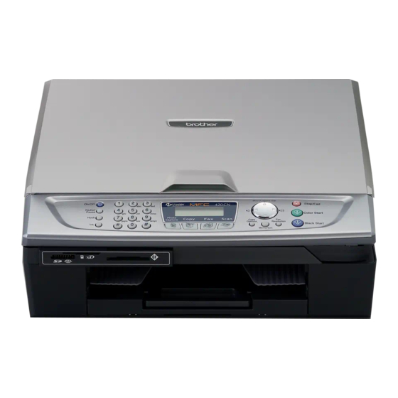
(5) Scanner cover (Scanner unit) (2) Paper tray (4) External telephone line jack (3) Telephone line jack Rear view (8) LAN cable connector* (9) Jam clear cover (7) USB interface connector *Provided on the MFC620CN/425CN/420CN/410CN and DCP315CN/310CN 1 - 1 Confidential... -
Page 13: Confidential
Document cover: Open to place the document (original) on the and FAX2440C) scanner glass. USB interface connector Connect the USB cable here. LAN cable connector Connect the LAN cable here. (MFC620CN/425CN/420CN/410CN and DCP315CN/DCP310CN) Jam clear cover Open to remove paper jammed inside the machine. 1 - 2 Confidential... - Page 14 1.2 CONTROL PANEL MFC620CN FAX2440C 1 - 3 Confidential...
- Page 15 Lets you listen to voice messages stored in memory. Also, lets you record telephone calls. 4. Mode keys Erase PhotoCapture (MFC620CN only) Lets you delete voice messages, all fax messages or all messages. Lets you access the PhotoCapture Center™ mode.
- Page 16 It also lets you dial stored numbers black and white. by pressing # and a two-digit number. Also for MFC620CN, lets you start a scanning operation. (Color or mono, depending on the scanning setting on your PC) Press to scroll backward to a menu selection.
- Page 17 MFC210C 1 - 6 Confidential...
- Page 18 1. Redial/Pause 5. Mode keys Redials the last number you called. It also inserts a PhotoCapture pause in auto dial numbers. Lets you access the PhotoCapture Center™ mode. 2. Hook Copy Press before dialing if you want to make sure a Lets you access Copy mode.
- Page 19 9. Color Start 12. Liquid Crystal Display (LCD) Lets you start sending faxes or making copies in full Displays messages on the screen to help you set up color. and use your MFC. The LCD examples in this guide are for models with a two-line display. There may be Also lets you start a scanning operation.
- Page 20 Ink absorber box Main PCB ASSY Lower cover Paper tray Hook switch PCB* Handset MJ/PS shield MJ PCB mount* Handset* Power supply * MFC620CN U.S.A./Canadian models and FAX2440C ** MFC620CN/425CN/420CN/DCP120C and FAX2440C *** MFC410CN/215C/210C andDCP315CN/310CN/117C/ 115C/110C 1 - 9 Confidential...
-
Page 21: Specifications
CHAPTER SPECIFICATIONS Confidential... -
Page 22: Table Of Contents
CHAPTER 2 SPECIFICATIONS This chapter lists the specifications of each model, which enables you to make a comparison of different models. CONTENTS GENERAL........................2-1 2.1.1 General Specifications..................2-1 2.1.2 Paper Specifications .................... 2-3 2.1.3 Printable Area ...................... 2-6 SPECIFICATIONS LIST ....................2-7 Confidential... -
Page 23: General
2.1 GENERAL 2.1.1 General Specifications The details below describe the MFC620CN. For the rest of the models, please refer to the 2.2 SPECIFICATION LIST. 16 MB Memory Capacity Up to 10 sheets Automatic Document Feeder (ADF) 100 sheets (20 lb.) - Page 24 Dimensions (W x D x H) MFC620CN U.S.A./Canadian models: 438 x 347 x 165 mm (17.3 x 13.7 x 6.5 inches) 454 x 455 x 165 mm (17.9 x 17.9 x 6.5 inches) (with paper tray and document stopper opened) 17.9"...
-
Page 25: Paper Specifications
2.1.2 Paper Specifications Recommended Paper Brother Paper Paper Type Item Paper Type Item Letter Plain BP60PL A4 Plain BP60PL Letter Glossy BP60GLL A4 Glossy BP60GLL Letter Inkjet (Photo Matte) BP60ML A4 Inkjet (Photo Matte) BP60ML Transparencies: 3M Transparency Film Paper Type and Size for Each Operation... - Page 26 Paper Weight, Thickness and Capacity Paper Type Weight Thickness No. of sheets Cut Sheet Plain Paper 64 to 120 g/m 0.08 to 0.15 mm (17 to 32 lb) (0.003" to 0.006") Inkjet Paper 64 to 200 g/m 0.08 to 0.25 mm (17 to 53 lb) (0.003"...
- Page 27 Do not use paper or envelopes: that are damaged, curled, wrinkled, or irregularly shaped that are extremely shiny or highly textured that were previously printed by a printer that cannot be arranged uniformly when stacked that are made with a short grain Do not use envelopes: that are of a baggy construction that are embossed (have raised writing on them)
-
Page 28: Printable Area
2.1.3 Printable Area The printable area depends on the settings in the application you are using. The figures below show the unprintable areas on cut sheet paper and envelopes. Cut Sheet Paper Envelopes unprintable area Paper (1) Top (2) Bottom (3) Left (4) Right 3 mm.(0.12in.) -
Page 29: Specifications List
2.2 SPECIFICATIONS LIST MFC210C/MFC420CN/MFC410CN (1/14) ASIA/OCE/CHN ASIA/OCE/CHN MFC-410CN MFC-410CN MFC-210C MFC-210C MFC-210C MFC-420CN Model name GENERAL Print Engine BH3 (KKCMY) BH3 (KKCMY) BH3 (KKCMY) BH3 (KKCMY) BH3 (KKCMY) BH3 (KKCMY) 74 nozzles/line 74 nozzles/line 74 nozzles/line 74 nozzles/line 74 nozzles/line 74 nozzles/line Technology Inkjet... - Page 30 100 (80 gsm) 100 (80 gsm) 100 (80 gsm) Output Paper Capacity (sheets) Optional Paper Tray (sheets) Brother Paper (for Plain,Glossy and LTR Plain / A4 Plain / A4 Plain / LTR Plain / A4 Plain / A4 Plain /...
- Page 31 (3/14) ASIA/OCE/CHN ASIA/OCE/CHN MFC-210C MFC-210C MFC-210C MFC-420CN MFC-410CN MFC-410CN Model name Dimensions with Carton (WxDxH)(mm) W 420 x W 500 x W 500 x W 420 x W 500 x W 500 x D 200 x H 380 D 200 x H 450 D 200 x H 450 D 200 x H 380 D 200 x H 450...
- Page 32 (4/14) ASIA/OCE/CHN ASIA/OCE/CHN MFC-210C MFC-210C MFC-210C MFC-420CN MFC-410CN MFC-410CN Model name LIST/REPORT Activity Report/Jour-l Yes (up to Yes (up to Yes (up to Yes (up to Yes (up to Yes (up to Report 200) 200) 200) 200) 200) 200) Transmission Verification Yes (in Menu Yes (in Menu Yes (in Menu...
- Page 33 (5/14) ASIA/OCE/CHN ASIA/OCE/CHN MFC-210C MFC-210C MFC-210C MFC-420CN MFC-410CN MFC-410CN Model name SUPPLIES/ OPTIONS Bundled Ink (Life / Yield) BK:500pages BK:500pages BK:500pages BK:500pages BK:500pages BK:500pages (Normal 5%) (Normal 5%) (Normal 5%) (Normal 5%) (Normal 5%) (Normal 5%) C/M/Y:400pag C/M/Y:400pag C/M/Y:400pag C/M/Y:400pag C/M/Y:400pag C/M/Y:400pag es(Normal 5%)
- Page 34 Kong only) Kong only) COLOR FAX Modem Speed(bps) 14,400(Fax) 14,400(Fax) 14,400(Fax) 14,400(Fax) 14,400(Fax) 14,400(Fax) Transmission Speed(sec.) Approx.6 Approx.6 Approx.6 Approx.6 Approx.6 Approx.6 (Brother#1,MM (Brother#1,MM (Brother#1,MM (Brother#1,MM (Brother#1,MM (Brother#1,MM ITU-T Group Coding Method Mono:MH/MR/ Mono:MH/MR/ Mono:MH/MR/ Mono:MH/MR/ Mono:MH/MR/ Mono:MH/MR/ MMR, MMR, MMR,...
- Page 35 Kong only) Kong only) COLOR FAX Modem Speed(bps) 14,400(Fax) 14,400(Fax) 14,400(Fax) 14,400(Fax) 14,400(Fax) 14,400(Fax) Transmission Speed(sec.) Approx.6 Approx.6 Approx.6 Approx.6 Approx.6 Approx.6 (Brother#1,MM (Brother#1,MM (Brother#1,MM (Brother#1,MM (Brother#1,MM (Brother#1,MM ITU-T Group Coding Method Mono:MH/MR/ Mono:MH/MR/ Mono:MH/MR/ Mono:MH/MR/ Mono:MH/MR/ Mono:MH/MR/ MMR, MMR, MMR,...
- Page 36 (8/14) ASIA/OCE/CHN ASIA/OCE/CHN MFC-210C MFC-210C MFC-210C MFC-420CN MFC-410CN MFC-410CN Model name COLOR PRINTER Color/Mono Color Color Color Color Color Color Resolution(dpi) up to up to up to up to up to up to 1200x6000 dpi 1200x6000 dpi 1200x6000 dpi 1200x6000 dpi 1200x6000 dpi 1200x6000 dpi Speed(ppm) Simple...
- Page 37 (9/14) ASIA/OCE/CHN ASIA/OCE/CHN MFC-210C MFC-210C MFC-210C MFC-420CN MFC-410CN MFC-410CN Model name Print Paper Margin (upper, lower, left, right) Borderless Borderless Borderless Borderless Borderless Borderless ON:0, 0, 0,0* ON:0, 0, 0,0* ON:0, 0, 0,0* ON:0, 0, 0,0* ON:0, 0, 0,0* ON:0, 0, 0,0* OFF:3,3,3,3mm/0.
- Page 38 (10/14) ASIA/OCE/CHN ASIA/OCE/CHN MFC-210C MFC-210C MFC-210C MFC-420CN MFC-410CN MFC-410CN Model name Paper Handling Size Letter/Legal/A Letter/Legal/A Letter/Legal/A Letter/Legal/A Letter/Legal/A Letter/Legal/A (Paper Tray) 4/A5/10x15cm 4/A5/10x15cm 4/A5/10x15cm 4/A5/10x15cm 4/A5/10x15cm 4/A5/10x15cm (4"W x6"H) (4"W x6"H) (4"W x6"H) (4"W x6"H) (4"W x6"H) (4"W x6"H) Paper Handling Size (2nd Tray) Paper Handling Size...
- Page 39 MESSAGE CENTER ICM Recording Time Toll Saver Memo/Recording Conversation OGM (MC/TAD,F/T) User Recording OGM TIME( MC/TAD, F/T ) PC FAX Supplier Brother Brother Brother Brother Brother Brother Color/Mono Mono Mono Mono Mono Mono Mono Sending Receiving...
- Page 40 (12/14) ASIA/OCE/CHN ASIA/OCE/CHN MFC-410CN MFC-410CN MFC-210C MFC-210C MFC-210C MFC-420CN Model name PHOTO CAPTURE CENTER Acceptable Media Card & Size SmartMedia SmarMedia SmartMedia SmartMedia SmartMedia SmartMedia (3.3V):4MB- (3.3V):4MB- (3.3V):4MB- (3.3V):4MB- (3.3V):4MB- (3.3V):4MB- 128MB 128MB 128MB 128MB 128MB 128MB Compact Flash Compact Flash Compact Flash Compact Flash Compact Flash...
- Page 41 (13/14) ASIA/OCE/CHN ASIA/OCE/CHN MFC-210C MFC-210C MFC-210C MFC-420CN MFC-410CN MFC-410CN Model name Media Format DPOF, Exif, DPOF, Exif, DPOF, Exif, DPOF, Exif, DPOF, Exif, DPOF, Exif, Image Format Photo Print: Photo Print: Photo Print: Photo Print: Photo Print: Photo Print: Print by PCC JPEG JPEG JPEG...
- Page 42 Remote Remote Setup) Setup) Setup) Network Management - (MIB-II as - (MIB-II as - (MIB-II as well as Brother well as Brother well as Brother private MIB) private MIB) private MIB) Network reset (in LAN Menu) (in LAN Menu) (in LAN Menu)
- Page 43 MFC620CN/DCP110C/DCP310CN (1/14) ASIA/OCE/CHN ASIA/OCE/CHN MFC620CN MFC620CN MFC620CN DCP-110C DCP-110C DCP- 310CN Model name GENERAL Print Engine BH3 (KKCMY) BH3 (KKCMY) BH3 (KKCMY) BH3 (KKCMY) BH3 (KKCMY) BH3 (KKCMY) 74 nozzles/line 74 nozzles/line 74 nozzles/line 74 nozzles/line 74 nozzles/line 74 nozzles/line...
- Page 44 100 (80 gsm) 100 (80 gsm) 100 (80 gsm) Output Paper Capacity (sheets) Optional Paper Tray (sheets) Brother Paper (for Plain,Glossy and LTR Plain / A4 Plain / A4 Plain / A4 Plain / A4 Plain / A4 Plain /...
- Page 45 (3/14) ASIA/OCE/CHN ASIA/OCE/CHN MFC620CN MFC620CN MFC620CN DCP-110C DCP-110C DCP- 310CN Model name Dimensions with Carton (WxDxH)(mm) W 552 x W 500 x W 500 x W 500 x W 500 x W 500 x D 225 x H 450 D 225 x H 450...
- Page 46 (4/14) ASIA/OCE/CHN ASIA/OCE/CHN MFC-620CN MFC-620CN MFC-620CN DCP-110C DCP-110C DCP-310CN Model name LIST/REPORT Activity Report/Jour-l Yes (up to Yes (up to Yes (up to Report 200) 200) 200) Transmission Verification Yes (in Menu Yes (in Menu Yes (in Menu Report Table) Table) Table) Cover page...
- Page 47 (5/14) ASIA/OCE/CHN ASIA/OCE/CHN DCP-110C DCP-110C DCP- 310CN MFC620CN MFC620CN MFC620CN Model name SUPPLIES/ OPTIONS Bundled Ink (Life / Yield) BK:500pages BK:500pages BK:500pages BK:500pages BK:500pages BK:500pages (Normal 5%) (Normal 5%) (Normal 5%) (Normal 5%) (Normal 5%) (Normal 5%) C/M/Y:400pag C/M/Y:400pag C/M/Y:400pag...
- Page 48 (6/14) ASIA/OCE/CHN ASIA/OCE/CHN MFC620CN MFC620CN MFC620CN DCP-110C DCP-110C DCP- 310CN Model name Handset Volume yes(2steps+A mplify) Speaker Volume Yes (3 steps + Yes (3 steps + Yes (3 steps + OFF) OFF) OFF) Ring Volume Yes (3 steps + Yes (3 steps +...
- Page 49 Pages Pages Pages (ITU-T Test Chart Memory Transmission UP to 480 UP to 480 UP to 480 Pages Pages Pages (Brother Chart/ MMR) ECM (Error Correction Mode) Error Re-Transmission Yes (130 Yes (130 Yes (130 Broadcasting (Speed+ locations) locations) locations)
- Page 50 (8/14) ASIA/OCE/CHN ASIA/OCE/CHN MFC620CN MFC620CN MFC620CN DCP-110C DCP-110C DCP- 310CN Model name COLOR PRINTER Color/Mono Color Color Color Color Color Color Resolution(dpi) up to up to up to up to up to up to 1200x6000 dpi 1200x6000 dpi 1200x6000 dpi...
- Page 51 (9/14) ASIA/OCE/CHN ASIA/OCE/CHN MFC620CN MFC620CN MFC620CN DCP-110C DCP-110C DCP- 310CN Model name Print Paper Margin (upper, lower, left, right) Borderless Borderless Borderless Borderless Borderless Borderless ON:0, 0, 0,0* ON:0, 0, 0,0* ON:0, 0, 0,0* ON:0, 0, 0,0* ON:0, 0, 0,0* ON:0, 0, 0,0* OFF:3,3,3,3mm/0.
- Page 52 (10/14) ASIA/OCE/CHN ASIA/OCE/CHN MFC620CN MFC620CN MFC620CN DCP-110C DCP-110C DCP- 310CN Model name Paper Handling Size Letter/Legal/A Letter/Legal/A Letter/Legal/A Letter/Legal/A Letter/Legal/A Letter/Legal/A (Paper Tray) 4/A5/100x150 4/A5/100x150 4/A5/100x150 4/A5/100x150 4/A5/100x150 4/A5/100x150 mm(4"Wx6H") mm(4"Wx6H") mm(4"Wx6H") mm(4"Wx6H") mm(4"Wx6H") mm(4"Wx6H") Paper Handling Size (2nd Tray)
- Page 53 (11/14) ASIA/OCE/CHN ASIA/OCE/CHN MFC620CN MFC620CN MFC620CN DCP-110C DCP-110C DCP- 310CN Model name Scan speed (Mono/Color) Maximum Maximum Maximum Maximum Maximum Maximum *@100dpi 3.54/5.58 3.54/5.58 3.54/5.58 3.54/5.58 3.54/5.58 3.54/5.58 second second second second second second @Letter_size @Letter_size @Letter_size @Letter_size @Letter_size @Letter_size Maximum.
- Page 54 (12/14) ASIA/OCE/CHN ASIA/OCE/CHN MFC620CN MFC620CN MFC620CN DCP-110C DCP-110C DCP- 310CN Model name PHOTO CAPTURE CENTER Acceptable Media Card & Size SmartMedia SmartMedia SmartMedia SmartMedia SmartMedia SmartMedia (3.3V):4MB- (3.3V):4MB- (3.3V):4MB- (3.3V):4MB- (3.3V):4MB- (3.3V):4MB- 128MB 128MB 128MB 128MB 128MB 128MB Compact Flash...
- Page 55 (13/14) ASIA/OCE/CHN ASIA/OCE/CHN MFC-620CN MFC-620CN MFC-620CN DCP-110C DCP-110C DCP-310CN Model name Media Format DPOF, Exif, DPOF, Exif, DPOF, Exif, DPOF, Exif, DPOF, Exif, DPOF, Exif, Image Format Photo Print: Photo Print: Photo Print: Photo Print: Photo Print: Photo Print: Print by PCC JPEG JPEG JPEG...
- Page 56 Setup) Setup) Setup) Setup) Network Management - (MIB-II as - (MIB-II as - (MIB-II as - (MIB-II as well as Brother well as Brother well as Brother well as Brother private MIB) private MIB) private MIB) private MIB) Network reset...
- Page 57 FAX2440C FAX-2440C FAX-2440C Model name GENERAL Print Engine BH3 (KKCMY) BH3 (KKCMY) 74 nozzles/line 74 nozzles/line Technology Inkjet Inkjet Scanning Method CPU Speed RISC 128MHz RISC 128MHz Back up Clock 1 hour 1 hour Operating Environment 5 - 35 (20-33) 5 - 35 (20-33) Temperature degrees...
- Page 58 Yes (10) Yes (10) Paper Capacity (sheets) 100 (80 gsm) 100 (80 gsm) Output Paper Capacity (sheets) Optional Paper Tray (sheets) Brother Paper (for Plain,Glossy and LTR Plain / A4 Plain / Inkjet) LTR Glossy/ A4 Glossy/ LTR Inkjet A4 Inkjet...
- Page 59 FAX2440C FAX2440C Model name Dimensions with Carton W 552 x W 552 x (WxDxH)(mm) D 225 x H 450 D 225 x H 450 Dimensions without W 438 x W 438 x Carton (WxDxH) * tray is D 347 x H 165 D 347 x H 165 not opened (mm) Dimensions without...
- Page 60 FAX-2440C FAX-2440C Model name LIST/REPORT Activity Report/Jour-l Yes (up to Yes (up to Report 200) 200) Transmission Verification Yes (in Yes (in Report Reports menu) Reports menu) Cover page Help List Yes (in Yes (in Reports menu) Reports menu) Call Back Message Caller ID List Yes(in CallerID...
- Page 61 FAX2440C FAX2440C Model name SUPPLIES/ OPTIONS Bundled Ink (Life / Yield) BK:500pages BK:500pages (Normal 5%) (Normal 5%) C/M/Y:400pag C/M/Y:400pag es(Normal 5%) es(Normal 5%) Supply Ink Cartridge (Life BK:500pages BK:500pages / Yield) (Normal 5%) (Normal 5%) C/M/Y:400pag C/M/Y:400pag es(Normal 5%) es(Normal 5%) Supply Ink Cartridge (Life BK:900pages BK:900pages...
- Page 62 USA ) Yes (U.K.(BT Distinctive Ringing Call Sign), Den. only) COLOR FAX Modem Speed(bps) 14,400(Fax) 14,400(Fax) Transmission Speed(sec.) Approx.6 Approx.6 (Brother#1,MM (Brother#1,MM ITU-T Group Coding Method Mono:MH/MR/ Mono:MH/MR/ MMR, MMR, Color:JPEG Color:JPEG Fax/Tel Switch Yes (by H/S or Yes (by H/S or S.Phone key)
- Page 63 Up to 250 Memory Transmission Pages Pages (ITU-T Test Chart UP to 300 UP to 300 Memory Transmission Pages Pages (Brother Chart/ MMR) ECM (Error Correction Mode) Error Re-Transmission Yes (136 Yes (136 Broadcasting (Speed+ locations) locations) OneTouch+Manual) Manual Broadcasting...
- Page 64 FAX2440C FAX2440C Model name Web DL Web DL COLOR PRINTER Option Option Color/Mono Color Color Resolution(dpi) up to up to 1200x6000 dpi 1200x6000 dpi Speed(ppm) Simple 20/15ppm 20/15ppm (Mono/Color: (Mono/Color: 600x150 dpi) 600x150 dpi) First print out time (from READY mode) Warm up Time ( from SLEEP mode ) Emulation...
- Page 65 FAX-2440C FAX-2440C Model name Print Paper Margin (upper, Borderless Borderless lower, left, right) ON:0, 0, 0,0* ON:0, 0, 0,0* OFF:0.12, 0.12, OFF:0.12, 0.12, 0.12, 0.12, 0,12"/3,3,3,3mm** 0,12"/3,3,3,3mm** * Borderless For * Borderless For /LTR/A6/Photo(4x6 /LTR/A6/Photo(4x6 "/102x152mm), "/102x152mm), Indexcard(5x8"/12 Indexcard(5x8"/12 7x203mm), Photo 7x203mm), Photo (3.5x5"/89x127mm (3.5x5"/89x127mm...
- Page 66 FAX2440C FAX2440C Model name Paper Handling Size Letter/Legal/A Letter/Legal/A (Paper Tray) 4/A5/100x150 4/A5/100x150 mm(4"Wx6"H) mm(4"Wx6"H) Paper Handling Size (2nd Tray) Paper Handling Size (Manual Slots) Paper Handling Size (MP) Media Type (Paper Tray) Plain, Inkjet, Plain, Inkjet, Glossy, Glossy, Transparency Transparency Media Type (2nd Tray) Media Type (Manual...
- Page 67 Conversation OGM (MC/TAD,F/T) User Recording OGM TIME( MC/TAD, F/T ) (20second) (20second) Web DL Web DL PC FAX Option Option Supplier Brother Brother Color/Mono Mono Mono Sending Receiving Protocol Compliance Broadcasting up to 50 up to 50 Support OS Version...
- Page 68 DCP115C/DCP120C 2 - 4 6 Confidential...
- Page 69 2 - 4 7 Confidential...
- Page 70 2 - 4 8 Confidential...
- Page 71 2 - 4 9 Confidential...
- Page 72 2 - 5 0 Confidential...
- Page 73 2 - 5 1 Confidential...
- Page 74 2 - 5 2 Confidential...
- Page 75 2 - 5 3 Confidential...
- Page 76 2 - 5 4 Confidential...
- Page 77 DCP315CN/MFC215C/MFC425CN 2 - 5 5 Confidential...
- Page 78 2 - 5 6 Confidential...
- Page 79 2 - 5 7 Confidential...
- Page 80 2 - 5 8 Confidential...
- Page 81 Yes (B&W only Yes (B&W only /not color) /not color) 2 - 5 9 Confidential...
- Page 82 2 - 6 0 Confidential...
- Page 83 2 - 6 1 Confidential...
- Page 84 2 - 6 2 Confidential...
- Page 85 2 - 6 3 Confidential...
- Page 86 2 - 6 4 Confidential...
-
Page 87: Theory Of Operation
CHAPTER THEORY OF OPERATION Confidential... - Page 88 CHAPTER 3 THEORY OF OPERATION This chapter gives an overview of the scanning and printing mechanisms as well as the sensors, actuators, and control electronics. It aids in understanding the basic principles of operation as well as locating defects for troubleshooting. CONTENTS OVERVIEW ........................
-
Page 89: Overview
- Carriage PCB with motor head flat cables - Carriage motor - Ink refill ASSY - Maintenance unit Handset ADF unit - ADF motor * MFC620CN U.S.A./Canadian models and FAX2440C ** MFC620CN and FAX2440C *** MFC620CN/425CN/420CN/DCP120C and FAX2440C **** MFC620CN/425CN/420CN/410CN Confidential... -
Page 90: Mechanical Components
3.2 MECHANICAL COMPONENTS This machine consists of the following mechanisms and uses three* motors, two encoders, various sensors, and a head thermistor. *Four motors are used in MFC620CN/425CN/420CN/DCP120C and FAX2440C. MFC620CN/425CN/420CN/ /DCP120C and FAX2440C CANNER MECHANI M PRINTING MECHANI M... - Page 91 Other Models SCANNER MECHANISM PRINTING MECHANISM (Front) Ink jet printing and head maintenance (head cap) mechanisms Paper pulling-in and Paper feeding and registration mechanisms ejecting mechanisms (Viewed from the left) SCANNER MECHANISM PRINTING MECHANISM (Front) Carriage drive mechanism Head maintenance mechanism (Head cap, purge, air vent, and head wiper) Confidential...
- Page 92 - Scanner open sensor - Registration sensor - Paper width (media) sensor - Ink cartridge sensors - Large-volume ink cartridge sensor (FAX2440C) - Purge cam switch - Hook switch sensor (MFC620CN U.S.A./Canadian models and FAX2440C) Thermistor - Head thermistor (See Section 3.2.3.)
-
Page 93: Scanner Mechanism
This mechanism consists of the document cover, the scanner unit (scanner cover), and the automatic document feeder (ADF)*. * MFC620CN/425CN/420CN/DCP120C and FAX2440C only. The scanner unit consists of a scanner top cover, CIS unit, CIS drive assembly, and scanner base. - Page 94 Document front sensor actuator Document pull-in roller Separation pad ADF motor Output document support Document feed roller Document Document Document tray guide roller Document cover (Right) Pinch rollers Document front sensor Document rear sensor actuator Document rear sensor Document separation roller Models with ADFs offer two types of scanning: ADF scanning and flat-bed scanning.
- Page 95 (1) ADF scanning: Document moves across stationary CIS unit (MFC620CN/425CN/420CN/DCP120C and FAX2440C only) Placing a document face down in the document tray activates the document front sensor, switching to ADF scanning. The CIS drive mechanism (details below) operates for each scanning command executed. The CIS unit first moves to the white-level reference film for white level compensation and then to the ADF scanning position.
-
Page 96: Printing Mechanism
3.2.2 Printing Mechanism 3.2.2.1 Paper pulling-in, registration, feeding and ejecting mechanisms These mechanisms are driven by a single paper feed motor located at the left of the engine unit via a gear train. (See the illustration on the next page.) The following illustration is a cross-sectional view of the machine viewed from the right. - Page 97 First, the paper feed motor rotates counterclockwise (when viewed from the output gear side). The motor rotation passes to the PF roller gear L and, via the ejection idle gear, the ejection roller gear to rotate the paper feed and ejection rollers in the reverse direction. At the right end of the paper feed roller is the PF roller gear R which is always engaged with the clutch gear and the idle gear L.
- Page 98 The outer circumference of the PF roller gear L functions as a 300 dpi (0.084 mm pitch) encoder disk which the PF encoder sensor uses to generate a signal indicating the gear rotation speed--in other words, the paper feed roller speed--to the controller for use in controlling paper feed position and speed.
-
Page 99: Ink Supply And Ink Jet Mechanism
3.2.2.2 Ink supply and ink jet mechanism [ 1 ] Overview The ink supply and ink-jet mechanism consists of the head/carriage unit, four ink cartridges, ink refill assembly, and ink supply tubes. The head/carriage unit scans the surface of the recording paper, jetting out ink supplied through the ink supply tubes onto the paper to produce images. -
Page 100: 2 ] Features
[ 2 ] Features A distinct feature of this machine is the use of ink supply tubes between the ink cartridges and the head/carriage unit. Relieving the head/carriage unit of the task of carrying heavy ink cartridges back and forth across the page, the approach generally adopted by other ink-jet printers, offers the following advantages. -
Page 101: 3 ] Head/Carriage Unit
[ 3 ] Head/carriage unit The head/carriage unit consists of a front end (ink-jet head) and a back end (buffer and air vent unit). The front end consists of metal plates laminated together and etched to form ink flow channels. (See illustration.) Piezoelectric ceramic actuators generate the spray pressure. - Page 102 Front end components and their main roles - Piezoelectric plate Applying a voltage stretches the plate, serving as the actuator for spraying ink. Consisting of thin piezoelectric plates laminated together, this plate can be driven even by a low voltage. - Filter This removes foreign matter from the ink.
- Page 103 Front end ASSY A’ Laminated electrode Channel Piezoelectric plate Nozzle plate Manifold Damper A - A’ 3-15 Confidential...
- Page 104 Back end Shutoff valve Damper ASSY (Color) Air vent unit (A part of head/carriage unit) Air vent rods Air vent cap (A part of maintenance unit) Damper ASSY (Black) Back end components and their main roles - Damper assembly This has two roles: dampening the ink pressure fluctuations** in the tubes as the carriage moves and collecting air bubbles that result from pressure changes on the ink.
- Page 105 Damping Without damping, ink pressure fluctuations directly affect the size of ink-jet head droplets, risking lower print quality. The damper structure for black differs from that for the colors (C, M, and Y) because black has twice nozzles used for each color, meaning higher ink flow rates and bigger pressure fluctuations. - Color dampers The three color damper assemblies each have two chambers.
- Page 106 Air bubble growth Liquid ink contains trace amounts of air. The amount varies with the pressure on the ink because increasing the pressure raises the ink's ability to absorb air from its surroundings and lowering the pressure forces the ink to give up some of this air. The ink pressure fluctuations generated by the piezoelectric ceramic actuators repeatedly expand and contract any air bubbles, causing them to gradually grow larger as the ink pressure changes repeatedly expand and contract them.
- Page 107 What's so bad about air bubble growth? Pressure fluctuations do not affect the volume of a liquid (ink), but Boyle's Law says that the volume of a gas (air) varies with the pressure on it. The main issue with air bubbles in the ink flow path is their damping effect, absorbing the pressure from the piezoelectric ceramic actuators and thus degrading ink-jet performance.
-
Page 108: 4 ] Ink Cartridges
"Pigment-based ink" Previous Brother machines used only dye-based inks. This one switches to a pigment-based ink for black only, reducing fuzziness from print character outlines, boosting resolution for black dots, and producing clearer images on plain paper. - Page 109 Ink cartridge components and their main roles - Disc valve S A plastic needle in the refill base opens this valve to supply air to the ink cartridge. Removing the ink cartridge closes this valve to prevent leakage due to ink backflow. - Disc valve D A plastic needle in the refill base opens this valve to allow ink to flow out of the ink cartridge.
-
Page 110: 5 ] Ink Refill Assembly
[ 5 ] Ink refill assembly Ink tube joints Ink cartridge base Cartridge clamp springs Ink refill base Ink cartridge joints Ink cartridge sensors Ink cartridge base Polyurethane foam 3-22 Confidential... - Page 111 Air flow path Ink flow path Ink refill assembly components and their main roles - Ink refill base This holds the ink cartridges and feeds ink from them to the ink supply tubes. - Cartridge clamp springs These force the ink cartridges into close contact with the ink cartridge joint to prevent ink leakage.
-
Page 112: 6 ] Ink Supply Tubes
[ 6 ] Ink supply tubes These are made of an elastomer providing a highly impermeable barrier against air ingress and drying out of the ink during extended periods of nonuse. This material is also soft and highly flexible to better withstand the sharp and frequent bending associated with high-speed head operation repeatedly over extended periods. -
Page 113: Head Maintenance Mechanism
3.2.2.3 Head maintenance mechanism [ 1 ] Maintenance mechanism components The head maintenance mechanism consists of the maintenance unit and the ink absorber box. (See the illustration below.) The maintenance unit has the following functions. - Locking the head/carriage unit - Capping the head nozzles to prevent them from drying up (See page 3-27.) - Page 114 - Planetary arm This switches power to the tube pump and pump switching unit depending on the direction of paper feed motor rotation. - Bevel gear This transmits the power from the clutch gear to the planetary arm. - Tube pump A roller squeezes the ink drain tubes looped inside, forcing their contents toward the ink absorber box and creating negative pressure.
-
Page 115: 3 ] Head Capping Mechanism
[ 3 ] Head capping mechanism When the power is off or the machine is not printing, this mechanism fits the head caps tightly over the print head to prevent the head nozzles from drying up and to keep dust off the print nozzle surface. -
Page 116: 4 ] Purge Mechanism
[ 4 ] Purge mechanism This mechanism draws its power from the paper feed motor on the left side of the main chassis. Gears between paper feed motor and maintenance unit As described in Section 3.2.2.1, the motor drives the PF roller gear L that rotates the paper feed roller. - Page 117 When the head/carriage unit travels from the left to right to reach the purge position, a tab on the carriage rear panel pushes the purge lever to the right (left in the illustration). The clutch gear spring pushes the clutch gear to the right, away from idle gear L, to mesh with the purge gear. At the purge position, therefore, the maintenance unit transmits the paper feed motor rotation to the bevel gear.
- Page 118 Switching arm assembly inside maintenance unit When the paper feed motor is driving the maintenance unit, counterclockwise (when viewed from the output gear side) rotation drives the purge cam; clockwise rotation, the tube pump. Main drain tube Air vent tube Purge cam Purge bevel gear Pump switching unit...
- Page 119 (1) Carriage lock Driving the purge cam pushes the carriage lock up and down. During the purge operation, the carriage lock pops out and locks the head/carriage unit to align ink-jet units with the mating head caps. After the purge operation, but before cleaning with the head wiper starts, the purge cam pulls in the carriage lock and releases the head/carriage unit.
- Page 120 (3) Head wiper After the purge operation, the purge cam pushes up the head wiper, wiping off any ink remaining on the head nozzle surface as the head/carriage unit moves from right to left. Maintenance unit Head wiper Purge cam (4) Switching pump The pump switching unit switches the negative pressure from the pump between the black head nozzles, the color head nozzles, and the air vent rod unit.
- Page 121 (5) Removing air Another position of the purge cam shifts the slide cams, producing vertical motion of the air vent rods. Pushing up the air vent rods opens the shut-off valves inside the air vent unit of the head/carriage unit. Simultaneously adding negative pressure from the tube pump expels air trapped in the manifolds.
- Page 122 Purge types, ink used, purge counts, and purge trigger keys Keys to trigger the purge, to be followed by Black Purge Start key Purge Types Description Ink Used Counts (See Note 2.) (See Note 1 for the DCP315CN/310CN /120C/115C/110C.) Normal purge This purge operation removes Black: 0.3 mL Black: 15...
- Page 123 (Note 1) To enter a numerical code on models having no numerical keypad, press the key several times to display the numerical code to be entered on the LCD and then press the Set key. After that, press the Mono Start key. 3-35 Confidential...
- Page 124 Ink cartridge capacities Ink cartridge type Contents Usable portion Spare cartridges Black ink cartridge High volume type* 30.3 mL Approx. 29.2 mL Low volume type 18.0 mL Approx. 16.9 mL Color ink cartridges 11.3 mL Approx. 10.5 mL Initial cartridges Black ink cartridge 21.5 mL Approx.
-
Page 125: Carriage Drive Mechanism
3.2.2.4 Carriage drive mechanism The head/carriage unit, which integrates the print head unit and carriage, is supported and guided by the CR guide rail and CR support chassis. The CR timing belt (1/25.4 inch pitch) transmits the carriage motor rotation to the carriage. Clockwise motor rotations move the carriage to the right; counterclockwise ones to the left. - Page 126 Adjusting print head angle relative to carriage For optimal image printing, the print head nozzle array must be perpendicular to the head/carriage unit's line of travel. Manufacturing limitations, however, make perfect alignment impossible during mass production. The angle must be adjusted at the individual machine level. The following describes this adjustment mechanism's components and their roles.
-
Page 127: Sensors And Actuators
(FAX2440C) Hook switch sensor On the hook switch PCB in Photosensor (MFC620CN U.S.A./Canadian models the lower cover and FAX2440C) • The document front sensor detects whether there is a document in the ADF. • The document rear sensor detects the leading and trailing edges of document pages, indicating to the control circuitry the point at which to start reading and when page scanning is complete. - Page 128 • There are four ink cartridge sensors, one for each color. The sensor actuator inside the ink cartridge usually blocks the light path to indicate the presence of ink. When ink runs low (near- empty), the arm moves out of the beam, activating the sensor. The same signal also indicates whether there is an ink cartridge present.
- Page 129 *FAX2440C **MFC620CN USA/Canadian models and FAX2440C (MFC620CN/425CN/420CN/ DCP120C and FAX2440C) Sensors and Actuators Locations 3-41 Confidential...
-
Page 130: Control Electronics
The following illustration shows the hardware components for this machine. The corresponding wiring diagram appears in Appendix MFC620CN/425CN/420CN/410CN and DCP/315CN/310CN Not provided on the DCP315CN/310CN/120C/117C/115C /110C FAX2440C MFC620CN U.S.A./Canadian models and FAX2440C MFC620CN/425CN/420CN DCP120Cand FAX2440C Not provided on the FAX2440C. MFC620CN/FAX2440C Machine Components 3-42 Confidential... - Page 131 CHAPTER TRANSFER OF DATA LEFT IN THE MACHINE TO BE SENT FOR REPAIR Confidential...
- Page 132 CHAPTER 4 TRANSFER OF DATA LEFT IN THE MACHINE TO BE SENT FOR REPAIR This chapter describes how to transfer data left in the machine to be sent for repair. The service personnel should instruct end users to follow the transfer procedure given in this chapter if the machine at the user site cannot print received data due to the printing mechanism defective.
-
Page 133: Transferring Received Fax Data
4.1 TRANSFERRING RECEIVED FAX DATA When the machine at the user site requires to be repaired, unplugging the power cord from the wall socket for sending the machine for repair will lose received FAX data if unprinted and left in the machine. - Page 134 (8) Enter the telephone number of the receiver machine and press the Menu/Set key again. NOTE: Be sure to type the telephone number with the numerical keys. No one-touch dialing is allowed in this procedure. The machine displays the "ACCEPTED" for approx. two seconds and starts dialing to transfer data.
- Page 135 Cover page sample Job number Total number of pages to be transferred Station ID registered in the sender equipment FAX number of the sender equipment Telephone number of the sender equipment Transfer start date Model code Boot ROM info ROM info Serial number End page sample Job number...
- Page 136 CHAPTER DISASSEMBLY/REASSEMBLY AND LUBRICATION Confidential...
- Page 137 Control Panel ASSY ..................5-24 5.1.7 Upper Cover....................... 5-26 5.1.8 Hook Switch Actuator and Hook Switch PCB (MFC620CN/620CN New U.S.A./ Canadian models and FAX2440C/2440C New) ..........5-27 5.1.9 Head/Carriage Unit .................... 5-29 5.1.9.1 Old Type of Head/Carriage Unit ..............5-29 5.1.9.2 New Type of Head/Carriage Unit...............
- Page 138 5.1.13 MJ/PS Shield Box, MJ PCB* and Power Supply PCB........5-53 5.1.14 Ink Absorber Box ....................5-55 5.1.15 Engine Unit and Maintenance Unit ..............5-57 5.1.16 Components on the Engine Unit................ 5-59 5.1.17 Routing of the Harnesses and Flat Cables............5-71 LUBRICATION ......................
-
Page 139: Disassembly/Reassembly
5.1 DISASSEMBLY/REASSEMBLY Safety Precautions To prevent the creation of secondary problems by mishandling, observe the following precautions during maintenance work. (1) Before replacing parts or units, unplug the power cord and telephone line. In particular, when having access to the power supply inside the machine, make sure that the power cord is unplugged from the electrical outlet;... -
Page 140: Tightening Torque
0.39 ±0.1 (4 ±1) Paper feed motor Screw, bind M3x3 0.39 ±0.1 (4 ±1) Provided on the MFC620CN/425CN/420CN/DCP120C and FAX2440C. The number of screws enclosed with parentheses is for the MFC215C/210C and DCP115C/117C/110C/. Provided on the MFC620CN/425CN/420CN/410CN, FAX2440C and DCP315CN/310CN/120C. -
Page 141: Preparation
- the handset mount (by pulling the tab and sliding the handset mount in the direction of the arrow shown below)*. (3) Remove memory cards if inserted in the machine. *MFC620CN U.S.A./Canadian models and FAX2440C Paper tray Telephone line cord... -
Page 142: Disassembly Flowchart
Disassembly Flowchart Confidential... - Page 143 Attach a piece of black adhesive tape. (3) Plug the power cord into an electrical outlet. MFC620CN/245CN/420CN/410CN/215C/210C and FAX2440C (4) Press the Menu/Set and Black Start keys. Next press the key four times to make the machine enter the maintenance mode.
- Page 144 (6) Make the head/carriage unit travel to the head replacement position (with Function code 63) by pressing the 6, 3 and * keys. For details, refer to Chapter 8, Section 8.5.13 "Travel Check of the Head/Carriage Unit and Initial Setup Mode." (7) Unplug the power cord from the electrical outlet.
-
Page 145: Jam Clear Cover
5.1.2 Jam Clear Cover (1) Press the two latches inwards and pull the jam clear cover out of the machine. Latch Latch Jam clear cover Confidential... -
Page 146: Document Cover (Mfc410Cn/215C/210C/210C New And Dcp310Cn/115C/117C/110C/110C New)
5.1.3 Document Cover (MFC410CN/215C/210C and DCP315CN/310CN/115C/117C/110C) For the MFC620CN/425CN/420CN/DCP120C and FAX2440C, remove the automatic document feeder (ADF) & document cover ASSY in Section 5.1.5 after separating the scanner cover from the machine in Section 5.1.4. Do not remove the document cover in the disassembly jobs except when replacing it. Performing disassembly jobs with the document cover being set prevents the scanner glass from getting scratched or damaged. -
Page 147: Scanner Cover (Scanner Unit)
MFC410CN/215C/210C and DCP315CN/310CN/115C/117C/110C: The document cover has been removed from the scanner cover in Section 5.1.3. MFC620CN/425CN/420CN/DCP120C and FAX2440C: The scanner cover still has the ADF & document cover ASSY whose removal procedure is described in Section 5.1.5. (1) Open the scanner cover to the left until it locks. - Page 148 (3) Open the scanner cover further. (4) Insert the tip of a flat screwdriver into the slot provided in the front end of the harness cover and slide the harness cover to the front. (5) Release the four latches of the CIS flat cable cover and lift it up. CIS flat cable cover Latches Scanner cover...
- Page 149 (6) MFC620CN/425CN/420CN/410CN, FAX2440C and DCP315CN/310CN/120C Disconnect the following cables and harnesses from the main PCB. - the CIS flat cable, - the panel-main harness, - the CIS motor harness, and - the ADF harness* Release the grounding wire by removing the screw*.
- Page 150 MFC215C/210C and DCP115C/117C/110C Disconnect the following cables and harnesses from the main PCB. - the CIS flat cable, - the panel-main harness, and - the CIS motor harness Cable guide Scanner cover (Scanner unit) "X" Press here. Panel-main harness CIS motor harness Main PCB �CIS flat cable (Front)
- Page 151 (8) Open the scanner cover at approx. 80° and pull it to the left and off the machine. NOTE: When replacing the scanner cover, remove the ferrite core from the CIS motor harness of the old scanner cover and set it to that of the new scanner cover. Wind the CIS motor harness round the ferrite core by one turn.
- Page 152 (10) Turn the scanner cover stopper upright and remove it from the upper cover by pressing the front and rear locks. Scanner cover stopper� � Upper cover� � Reassembling Notes • When replacing the scanner cover: Please refer to the Rating Label on the right. If the model can be determined by the character “Z”...
-
Page 153: Adf & Document Cover Assy
5.1.5 ADF & Document Cover ASSY (MFC620CN/425CN/420CN/DCP120C and FAX2440C) (1) As shown below, press the hatched section on the left edge of the scanner cover outwards to provide enough gap and pull out the ADF harness, CIS motor harness, and grounding wire from the cable guide. - Page 154 < Disassembly of the ADF & document cover ASSY > ADF cover ASSY 1) Slightly warp the ADF cover ASSY and remove it from the bosses provided on the front and rear side of the ADF & document cover ASSY. Hole ADF cover ASSY Hole...
- Page 155 3) Remove the ADF pull-in piece and its spring from the ADF cover. ADF cover ADF pull-in piece ADF pull-in spring 4) Remove the separation pad from the ADF cover. ADF cover Separation pad Confidential 5-17...
- Page 156 Document stopper and document ejection films 5) Remove the document stopper. 6) Remove the document ejection films. NOTE: Once removed, the document ejection films will become unusable and new parts will have to be put back in. Document stopper Document ejection films ADF &...
- Page 157 Document guides (F and R) 8) Remove the screw from the document guide gear. Take the document guide gear and its spring out of the document cover. 9) As shown below, slide each of the document guides F and R inwards ( ), pull down the bottom end ( ), slide it inwards further, and take it up ( ).
- Page 158 Document front and rear sensor actuators 10) Lightly press the locking arm for each of the document front and rear sensor actuators, slide the actuator towards the locking arm, and remove it in the direction of the arrow shown below. The actuator springs also come off.
- Page 159 ADF motor and document feed roller 11) Take the ADF harness and grounding wire out of the harness guide provided on the ADF unit. 12) Remove the screw that secures the grounding wire and ADF motor together. 13) Remove the screw from the ADF motor and disconnect the ADF harness from the motor. 14) Remove the pawl bushing from the front end of the document feed roller shaft and remove the document feed roller gear from the read end.
- Page 160 Document front and rear sensors, document pull-in roller, and document separation roller 15) Remove the two screws and take the ADF reinforcement plate off the ADF unit. 16) Remove the document front and rear sensors by unhooking the three latches each. Disconnect the ADF harness from each sensor.
- Page 161 Reassembling Notes • Route the ADF harness (consisting of the ADF motor harness and document front and rear sensor harnesses) on the ADF unit as shown below. Routing of the document rear sensor harness (of the ADF harness) Document rear sensor (Front) Document front sensor Routing of the document front...
-
Page 162: Control Panel Assy
5.1.6 Control Panel ASSY (1) Turn the scanner cover (scanner unit) upside down, push the left side outwards, and take out the panel-main harness. (2) Remove the three screws from the underside of the scanner cover. (3) Pull up the rear end of the control panel ASSY and take it off the scanner cover. 5-24 Confidential... - Page 163 4) Press the two "Y" latches inwards to release the scanner open sensor actuator. The actuator spring also comes off. 5) MFC620CN/FAX2440C: Remove the microphone from the control panel. 6) Pull the locking arms outward and take out the LCD while pulling the LCD flat cable gently.
-
Page 164: Upper Cover
5.1.7 Upper Cover (1) Remove the four screws from the upper cover. (2) Release the five retainers provided on the upper cover and lift up the upper cover. Retainer Upper cover Taptite, bind B M4x12 Retainer Retainers Lower cover Retainer Reassembling Notes •... -
Page 165: Hook Switch Actuator And Hook Switch Pcb (Mfc620Cn/620Cn New U.s.a./Canadian Models And Fax2440C/2440C New)
5.1.8 Hook Switch Actuator and Hook Switch PCB (MFC620CN/620CN New U.S.A./Canadian models and FAX2440C/2440C New) (1) Pull the hook switch actuator outwards, turn it counterclockwise to release it from the boss, and take it up and out of the lower cover. - Page 166 (2) Disconnect the hook switch harness from the main PCB. (3) Insert the tip of a flat screwdriver through the square cutout provided in the bottom of the machine, release the latch to the front, and lift up the hook switch PCB. Confidential 5-28...
-
Page 167: Head/Carriage Unit
5.1.9 Head/Carriage Unit During disassembly jobs, except when removing the ink refill ASSY or engine unit (including the maintenance unit), leave the head/carriage unit and all four ink cartridges in the machine. Before removing the head/carriage unit, ink refill ASSY or engine unit, you need to replace the current ink cartridges with dummy ones and drain ink from the ink refill ASSY and head/carriage unit (see Section... - Page 168 Removing the head cover (2) Unlatch the head cover from the head/carriage unit and pull it up. Head cover Latches Latches Head/carriage unit Ejection idle gear Confidential 5-30...
- Page 169 Releasing the head flat cables from the head joint (3) Disconnect the head flat cables 1 and 2 from the main PCB and pull them out to the rear through the opening provided in the lower cover as shown below. NOTE: Take care not to drop the flat core from the head flat cables.
- Page 170 Removing the head joint from the head/carriage unit (5) While turning up the head flat cables, pull the joint leaf spring to the right to release the head joint. (6) Pull the head joint up and off the head/carriage unit, taking care not to contaminate the head flat cables with ink remaining on the section where the head joint was mounted.
- Page 171 Removing the head/carriage unit and CR timing belt NOTE: During the removal or installation job for the head/carriage unit, take care not to contaminate the CR encoder strip or PF encoder disk with grease applied to the head/carriage unit. NOTE: Do not disassemble the old type of the head/carriage unit. Always handle it together with the carriage PCB and head flat cables.
- Page 172 (12) A head/carriage unit is assigned a property code that represents the properties unique to that head/carriage unit. The property code is printed on a property label that is attached to the carriage-head flat cable and the machine. When you remove the head/carriage unit and store it separately from the machine, remove the property label from the machine and store it together with the head/carriage unit.
- Page 173 NOTE: When storing the head/carriage unit for a long period, be sure to put an air buffer cap on the head/carriage unit and store the unit in the head casing, as shown below. Leaving the head/carriage unit out of the casing will cause the print nozzles and ink supply ports to dry up, resulting in a damaged head.
- Page 174 5) Route the head flat cable 1 as shown on page 5-31 and secure it to the lower cover with the double-sided adhesive tape attached in 1) above. 6) Attach the FFC support film to the head flat cable 2 as shown below, bend it at the right-hand position to fit it into section "a"...
-
Page 175: New Type Of Head/Carriage Unit
5.1.9.2 New Type of Head/Carriage Unit Draining the ink from the ink supply tubes and moving the head/carriage unit to the head replacement position (Refer to Section 5.1.1.) (1) Make sure that: - the ink in the ink refill ASSY and head/carriage unit has been drained, - all four ink cartridges have been replaced with protective cartridges, - the head/carriage unit is placed in the head replacement position, and - the power cord is unplugged from the electrical outlet. - Page 176 Removing the carriage PCB and head flat cables (3) Disconnect the head flat cables 1 and 2 from the main PCB and pull them out to the rear through the opening provided in the lower cover as shown below. NOTE: Take care not to drop the flat core from the head flat cables. (4) Slide the FFC support to the rear and lightly pull up the cable clamp to release the support from the cable clamp.
- Page 177 (7) Pull up the front edge of the carriage PCB to release the rear edge from the two latches provided on the head/carriage unit. Then lift the carriage PCB up and out of the head/carriage unit. Carriage PCB Flat core Latches Head/carriage unit Cable clamp on the head joint...
- Page 178 Removing the head joint (8) Pull the joint leaf spring to the right to release the head joint. (9) Pull the head joint up and off the head/carriage unit. Remove the head joint rubber (that is a part of the head/carriage unit but may be attached to the head joint) and put it on a clean vinyl sheet while taking care not to contaminate it.
- Page 179 Removing the head/carriage unit and CR timing belt NOTE: During the removal or installation job for the head/carriage unit, take care not to contaminate the CR encoder strip or PF encoder disk with grease applied to the head/carriage unit. (10) While pressing the idle pulley to the right, remove the CR timing belt from the carriage motor pulley and idle pulley.
- Page 180 (14) A head/carriage unit is assigned a property code that represents the properties unique to that head/carriage unit. The property code is printed on a property label that is attached to the carriage-head flat cable and the machine. When you remove the head/carriage unit and store it separately from the machine, remove the property label from the machine and store it together with the head/carriage unit.
- Page 181 NOTE: When storing the head/carriage unit for a long period, be sure to put an air buffer cap on the head/carriage unit and store the unit in the head casing, as shown below. Leaving the head/carriage unit out of the casing will cause the print nozzles and ink supply ports to dry up, resulting in a damaged head.
- Page 182 6) Fit the FFC support to the head joint, sliding it along the joint's cable clamp. 7) Route the head flat cable 1 as shown on page 5-38 and secure it to the lower cover with the double-sided adhesive tape attached in 1) above. 8) Mount the head cover.
-
Page 183: Backup Battery (Mfc620Cn/620Cn New/Fax2440C/2440C New)
5.1.10 Backup Battery (MFC620CN,FAX2440C) (1) Disconnect the battery harness from the main PCB. (2) Release the ink supply tubes routed on the lower cover from the tube guides. NOTE: Releasing those tubes makes it easy to release the battery harness from the hook provided on the lower cover since the battery harness is routed beneath those tubes. - Page 184 Reassembling Notes • Route the battery harness (MFC620CN,FAX2440C) and large-volume ink cartridge harness (FAX2440C) beneath the ink supply tubes as shown below. 5-46 Confidential...
-
Page 185: Ink Refill Assy
5.1.11 Ink Refill ASSY (1) Take the ink supply tubes routed on the lower cover out of the machine. (2) Press the latch provided on the front side of the ink cartridge base inwards with a flat screwdriver and lift the ink cartridge base up and out of the lower cover. NOTE: Inside the ink cartridge base is an ink absorber foam that may be stained with ink. -
Page 186: Media Module Cover And Main Pcb
Observing this sequence prevents harnesses and flat cables from getting crushed or damaged by screws or screwdrivers. The following procedure is for the MFC620CN/MFC425CN/420CN/410CN,FAX2440C and DCP315CN/310CN/120C. In the MFC215C/210C and DCP117C/115C/110C, the number of screws and the shapes of the main PCB and its shield differ. - Page 187 (5) Disconnect the following harnesses and flat cables from the main PCB. CAUTION: Do not remove the screws from the main PCB before disconnecting harnesses and flat cables. MFC620CN /420CN/410CN, FAX2440C and DCP310CN - Power supply harness (4-pin) - PF motor/sensor PCB harness (7-pin)
- Page 188 MFC215C/210C/210C New and DCP117C/115C/110C - Power supply harness (4-pin) - PF motor/sensor PCB harness (7-pin) - Carriage motor harness (2-pin) - MJ-main harness 1 (2-pin)* - Speaker harness (2-pin) - Head flat cable 1 (17-pin) - Head flat cable 2 (19-pin) *Not provided on the DCP117C/115C/110C.
- Page 189 MFC425CN and DCP315CN/120C - Power supply harness (4-pin) - PF motor/sensor PCB harness (7-pin) - Carriage motor harness (2-pin) - MJ-main harness 1 (2-pin)* - Speaker harness (2-pin) - Head flat cable 1 (17-pin) - Head flat cable 2 (19-pin) (6) Remove four screws (three "d"...
- Page 190 ain PCB "e" SDAA enclosure "d" "d" "c" ain PCB film "d" Thermal conductor ain PCB shield frame rubber Ink cartridge/purge cam switch harness Lower cover NOTE: Screw tightening orde r First tighten screws "d" and "e" and then screw "c." Power supply harness J-line harness (2-pin) J-main harness 1 (2-pin)
- Page 191 • If the main PCB is replaced, attach the thermal conductor rubber removed from the old PCB to a new one as specified below. NOTES: Thermal conductor rubber is used on the models MFC620CN/425NC/420CN/205C/210C, FAX2440C of Europe, Asia and Oceania.
-
Page 192: Mj/Ps Shield Box, Mj Pcb* And Power Supply Pcb
5.1.13 MJ/PS Shield Box, MJ PCB* and Power Supply PCB *Not provided on the DCP315CN/310CN/120C/117C/115C/110C (1) Remove the two screws. (2) Insert the tip of a flat screwdriver through square cutout "x" and push boss "X" inwards to release the MJ/PS shield box. 5-54 Confidential... - Page 193 (3) Remove screw "a" from the MJ shield and take it off the lower MJ/PS shield. (4) Remove the power supply shield. (5) Remove five screws ("c" and "d1" through "d4" screws) from the grounding terminal and power supply PCB. (6) Remove screw "b"...
-
Page 194: Ink Absorber Box
5.1.14 Ink Absorber Box (1) Pull out the two tubes (main drain tube and opening tube to the atmospheric air) from the ink absorber box. NOTE: Pinch the end of the main drain tube with a clip to prevent drained ink from leaking and the machine from getting stained with leaked ink. - Page 195 • If you replace the ink absorber box (without replacing the main PCB), you need to reset the purge counter in the EEPROM to zero according to the procedure below. MFC620CN/425CN/420CN/410CN/215C/210C and FAX2440C 1) Press the Menu/Set and Black Start keys. Next press the key four times to make the machine enter the maintenance mode.
-
Page 196: Engine Unit And Maintenance Unit
5.1.15 Engine Unit and Maintenance Unit During disassembly jobs, except when removing the ink refill ASSY or engine unit (including the maintenance unit), leave the head/carriage unit and all four ink cartridges in the machine. Before removing the head/carriage unit, ink refill ASSY or engine unit, you need to replace the current ink cartridges with dummy ones and drain ink from the ink refill ASSY and head/carriage unit (see Section... - Page 197 Removing the maintenance unit and related parts (2) Remove two screws, "e" from the top of the engine unit and "f" from the right side of the maintenance unit. (3) Remove the maintenance unit. (4) Unlatch the purge cam switch from the maintenance unit. (5) Remove the purge-related parts from the engine unit as shown below.
-
Page 198: Components On The Engine Unit
5.1.16 Components on the Engine Unit Removing the CR encoder strip (1) Unhook the CR encoder strip from the engine unit. NOTE: Take care not to scratch or damage the encoder strip. If it becomes dirty, wipe it with a soft, dry cloth. - Page 199 Removing the paper pull-in gear shaft and roller holder (2) Press the locking arm and pull out the paper pull-in gear shaft to the right. (3) Remove the paper pull-in roller holder. Engine unit Paper pull-in gear shaft Paper pull-in roller holder Locking arm Viewed from the bottom Paper pull-in gear shaft...
- Page 200 Removing the paper ejection roller (4) At the left end of the paper ejection roller, release the lock arm of bushing L from the hole provided in the chassis of the engine unit and turn bushing L clockwise (viewed from the right). At the right end, release the lock arm of bushing R from the chassis and turn it clockwise to the horizontal position, then remove the paper ejection roller towards you.
- Page 201 Removing the platen (5) Pull out the platen towards you. Edge "B" CR support chassis CR guide rail Paper feed roller shaft "A" Slit "b" "a" Platen Reassembling Note: Make sure that section "a" and slit "b" on the platen are fitted over paper feed roller shaft "A"...
- Page 202 Removing the star wheel holder ASSY (6) Release the two latches provided on the star wheel holder ASSY from the CR support chassis and take the ASSY out of the engine unit. Latches Star wheel holder ASSY CR guide rail CR support chassis Carriage motor harness Confidential...
- Page 203 Removing the paper pressure holder and registration sensor actuator (7) Release the latch provided on the paper pressure holder from the engine unit and remove the holder to the left and rear. The four paper pressure springs also come off. Latch Paper pressure springs Paper pressure holder...
- Page 204 (8) Unhook the sensor actuator spring from the paper pressure holder and turn the registration sensor actuator in the direction of the arrow as shown below to release it. Sensor actuator spring Registration sensor actuator Registration sensor actuator Paper pressure holder Sensor actuator spring Hooking the sensor actuator spring Confidential...
- Page 205 Removing the flushing case (9) Press the locking pawl from the bottom of the flushing case and slide the case to the right and rear. Flushing case Engine unit Boss PF motor/sensor PCB harness Boss Locks Locking pawl Viewed from the bottom Confidential 5-67...
- Page 206 Removing the carriage motor (10) Release the carriage motor from the engine unit by removing the two screws. Screw, bind M3x3 CR guide rail CR support chassis Carriage motor Confidential 5-68...
- Page 207 Removing the PF sensor PCB (11) Disconnect the PF motor/sensor PCB harness from the PF sensor PCB. (12) Remove the screw from the PF sensor PCB and release the PCB from the engine unit, taking care not to touch the PF encoder disk. Paper feed roller Engine unit PF motor/sensor PCB harness...
- Page 208 Removing the PF encoder disk, ejection idle gear and paper feed motor (13) Peel off the PF encoder disk from the PF roller gear only when it should be replaced. NOTE: Once removed, the PF encoder disk will become unusable and a new disk will have to be put back in.
- Page 209 (15) Remove the two screws and release the paper feed motor from the engine unit. To the PF sensor PCB Paper feed motor Paper feed roller Engine unit PF roller gear L PF motor/sensor PCB Screw, bind M3x3 harness Reassembling Note: When attaching the PF encoder disk to the PF roller gear, put on clean gloves to protect the disk surface from dust or fingerprints.
-
Page 210: Routing Of The Harnesses And Flat Cables
5.1.17 Routing of the Harnesses and Flat Cables Routing A: ADF harness on the ADF unit (MFC620CN/425CN/420CN/DCP120C and FAX2440C) Routing of the document rear sensor harness (of the ADF harness) Document rear sensor (Front) Document front sensor Routing of the document front... - Page 211 Routing B: Panel-main harness on the underside of the control panel ASSY MFC620CN/FAX2440C Cable guides Control panel ASSY placed upside down MFC425CN/420CN/410CN/215C/210C and DCP315CN/310CN/120C/117C/115C/110C Cable guides Control panel ASSY placed upside down Ribs 5-73 Confidential...
- Page 212 Routing C: Backup battery harness and ink supply tubes (MFC620CN and FAX2440C) 5-74 Confidential...
- Page 213 Routing D: Harnesses, flat cables and ink tubes on the lower cover MFC620CN/425CN/420CN/410CN, FAX2440C, and DCP315CN/310CN/120C Top view 5-75 Confidential...
- Page 214 Viewed from the left 5-76 Confidential...
- Page 215 MFC215C/210C and DCP117C/115C/110C Top view Carriage motor harness (2-pin) MJ-main harness 1 (2-pin) MJ-line harness (2-pin) Speaker harness (2-pin) Ink supply tubes PF motor/sensor PCB harness (7-pin) CIS motor harness (4-pin) Panel-main harness (5-pin) Power supply harness (4-pin) Head flat cables (17- and 19-pin) Purge cam switch harness (2-pin) Ink cartridge/purge cam...
- Page 216 Viewed from the left MJ-line harness (2-pin) Speaker harness (2-pin) CIS motor harness (4-pin) MJ-main harness 1 (2-pin) Panel-main harness PF motor/sensor PCB harness (7-pin) Carriage motor harness (2-pin) Power supply harness (4-pin) (Main PCB) 5-78 Confidential...
- Page 217 Routing E: MJ-main harness* and MJ-line harness* through the SDAA enclosure *Not provided in the DCP315CN/310CN/120C/117C/115C/110C CIS motor harness and Panel-main harness Speaker harness MJ-main harness* MJ-line harness* Main PCB SDAA enclosure Routing F: Power cord, MJ-main harness* and MJ-line harness* in the MJ/PS shield box *Not provided in the DCP315C/310CN/120C/117C/115C/110C Power supply shield Power cord...
-
Page 218: Lubrication
5.2 LUBRICATION Apply the specified lubricants to the lubrication points as shown below. Lubricant type (Manufacturer) Lubrication points Lubricant amount Molykote EM-60L Head/carriage unit 3 mm dia. ball (Dow Corning) Molykote EM-30LG Document pull-in roller 4 mm dia. ball (Dow Corning) Document separation roller Head/carriage unit Apply a 3 mm dia. - Page 219 Document pull-in roller and document separation roller Apply a 4 mm dia. ball of grease (Molykote EM-30LG) to each of the following lubrication points. 5-81 Confidential...
- Page 220 CHAPTER ADJUSTMENTS AND UPDATING OF SETTINGS, REQUIRED AFTER PARTS REPLACEMENT Confidential...
-
Page 221: Required After Parts Replacement
CHAPTER 6 ADJUSTMENTS AND UPDATING OF SETTINGS, REQUIRED AFTER PARTS REPLACEMENT This chapter details adjustments and updating of settings, which are required if the head/carriage unit, main PCB and some other parts have been replaced. CONTENTS PREPARATION ....................... 6-1 6.1.1 Requirements ...................... - Page 222 [ 12 ] Load the firmware designed for the corresponding model to the flash ROM (Required for the MFC210C U.S.A./Canadian models)....6-28 [ 13 ] Switch back to standby (Required for the MFC620CN/425CN/420CN /410CN) ..................... 6-28 IF YOU REPLACE THE INK ABSORBER BOX............6-29 Reset the purge counter to zero with the following procedure.
-
Page 223: Preparation
6.1.1 Requirements Before proceeding to perform any adjustments or update any settings, you need to have the executables, files, spare parts and supplies (provided by Brother Industries) on hand and set up your PC. NOTE: Use a PC/AT-compatible computer running Windows 98SE, Windows Me, Windows 2000 Professional, or Windows XP Home/Professional. -
Page 224: Loading The Update Programs/Data To The Machine
PCB and load update programs/data to a new PCB. Preparation You need to have the BHL2-Maintenance Printer driver and FILEDG32.exe (provided by Brother Industries) on hand. Save them in an arbitrary folder in your PC. Installing the BHL2-Maintenance Printer driver To identify terminals connected via USB interface, a PC requires the corresponding virtual USB devices to be implemented by driver/software. - Page 225 (6) The following screen appears, indicating the detection of new hardware device by the system. Click Next to proceed. (7) Select "Search for a suitable driver for my device (recommended)" and click Next. (8) Select "Specify a location" and click Next. 6 - 3 Confidential...
- Page 226 (9) Select the folder where the copy of the BHL2-Maintenance Printer driver is located (or click Browse to specify it), then click OK. (This sample screen is captured on the Windows 2000 desktop.) (10) Click Next. (11) To proceed, click Yes. 6 - 4 Confidential...
- Page 227 (12) If the driver is successfully installed, the following message window appears. Click Finish to return to Windows. NOTE: After completion of the driver installation, if the machine exits the maintenance mode, the "Found New Hardware Wizard" screen in step (6) appears again. Click Cancel. NOTE: To check that the printer driver is successfully installed, click Start|Settings|Printers to call up the Printers window as shown below and confirm that the BHL2-Maintenance Printer icon is displayed.
-
Page 228: Embedded And Full Maintenance Programs
6.1.3 Embedded and Full Maintenance Programs The maintenance program embedded in some models (MFC210C U.S.A./Canadian models only) is a part of the full maintenance program as shown in the table below. If you need to use functions not supported by the embedded maintenance program (e.g., 09, 12, 54, ...), temporarily load the full maintenance program via the work PC to the flash ROM of the machine to be repaired. -
Page 229: If You Replace The Head/Carriage Unit Or Engine Unit
6.2 IF YOU REPLACE THE HEAD/CARRIAGE UNIT OR ENGINE UNIT [ 1 ] Load the full maintenance program temporarily (Required for the MFC210C U.S.A./Canadian models) NOTE: Before proceeding the program loading procedure, install the printer driver to the work PC. (Refer to Appendix NOTE: The full maintenance program file (LZ****. -
Page 230: 2 ] Update The Head Property Information Stored In The Eeprom On The Main Pcb
[ 2 ] Update the head property information stored in the EEPROM on the main PCB For the MFC210C U.S.A./Canadian models, skip steps (1) through (3) below. (1) Make sure that the machine's power cord is unplugged from an electrical outlet. If the machine is connected to a PC, unplug the USB cable. - Page 231 (8) In Port, select the port number assigned to the BHL2-Maintenance Printer. To confirm the port number, follow the instructions below. Click Start | Settings | Printers. The Printers window appears as shown below. Right-click the BHL2-Maintenance Printer icon. Click Properties. 6 - 9 Confidential...
- Page 232 The BHL2-Maintenance Printer Properties window appears as shown below. Click the Ports tab. The port number assigned to the Brother BHL2-Maitenance Printer, USB010 in this example, is one that has been selected in Port on the BrUsbSn screen (page 6-8).
-
Page 233: 3 ] Clean The New Head/Carriage Unit
[ 3 ] Clean the new head/carriage unit MFC620CN/425CN/420CN/410CN/215C/210C and FAX2440C (1) Open the scanner unit (scanner cover), set new ink cartridges into the ink refill ASSY, and close the scanner unit. (2) Carry out "Initial purge" (with Function code 76) using the steps below. (See... -
Page 234: 4 ] Correct The Positioning Error Of The Head/Carriage Unit
[ 4 ] Correct the positioning error of the head/carriage unit (1) Run "FILEDG32.exe" in the folder created. The Filedrgs window appears as shown below. (2) Drag and drop the "INCLINE.PRN" icon onto the BHL2-Maintenance Printer icon in the Filedrgs window shown above. The "Incline Adjust"... - Page 235 (4) Move the head/carriage unit to the head replacement position (with Function code 63) using the following key operation. MFC620CN/425CN/420CN/410CN/215C/210C and FAX2440C Press the 6, 3, and * keys in this order. DCP315CN/310CN/120C/115C/117C/110C Enter 6, 3, and * by using the and Set keys.*...
-
Page 236: 5 ] Update The Paper Feeding Correction Value
The machine displays the "RECEIVING DATA" on the LCD and prints out "PF adjust check" patterns (see page 6-16 for a sample printout). (3) MFC620CN/425CN/420CN/410CN/215CN/210C and FAX2440C Press the 5 and 8 keys on the machine. DCP315CN/310CN/120C/115C/117C/110C and Set keys on the machine.*... - Page 237 Set key. Repeat this operation for each symbol or numerical code.) The machine automatically returns to the initial stage of the maintenance mode. (7) MFC620CN/425CN/420CN/410CN/215C/210C and FAX2440C Press the 5 and 8 keys on the machine. DCP315CN/310CN/120C/115C/117C/110C and Set keys on the machine.*...
- Page 238 "A" ⇒ "B" ⇒ Paper Feeding Check Patterns for the Paper Feed Roller and Paper Ejection Roller 6 - 1 6 Confidential...
-
Page 239: 6 ] Align Vertical Print Lines
[ 6 ] Align vertical print lines (1) MFC620CN/425CN/420CN/410CN/215C/210C and FAX2440C Press the 6, 5 and 1 keys in this order. DCP315CN/310CN/120C/115C/117C/110C and Set keys on the machine.* Enter 6,5, and 1 by using the (*To enter a numerical code on models having no numerical keypad, press the key several times to display the numerical code to be entered and then press the Set key. - Page 240 Vertical Alignment Check Patterns 6 - 1 8 Confidential...
-
Page 241: 7 ] Margin Adjustment In Near-Edge Printing
(Example) Left: 1.0 mm, Right: 1.3 mm If both margins are within the range from 0.9 to 1.1 mm, no adjustment is required. (4) MFC620CN/425CN/420CN/410CN/215C/210C and FAX2440C If either margin is out of the specified range, press the 6 key twice on the machine. - Page 242 (6) Enter the measured value (in units of 0.1 mm) multiplied by 10. (Example) Left: 10, Right: 13 MFC620CN/425CN/420CN/410CN/215C/215C/210C and FAX2440C In this example, press the 1, 0, Menu/Set, 1, 3, and Menu/Set keys. DCP315C/310CN/120C/115C/117C/110C In this example, enter 1, 0, 1, and 3 by using the and Set keys.*...
- Page 243 Margin Check Pattern 6 - 2 1 Confidential...
-
Page 244: Print Out A Test Pattern
[ 8 ] Print out a test pattern MFC620CN/425CN/420CN/410CN/215C/215C/210C and FAX2440C Press the 0 and 9 keys in this order. DCP315C/310CN/120C/115C/117C/110C Enter 0 and 9 by using the and Set keys.* (*To enter a numerical code on models having no numerical keypad, press the key several times to display the numerical code to be entered and then press the Set key. -
Page 245: 10 ] Switch Back To Standby
6.1.2). Click Cancel on the wizard screen. [ 10 ] Switch back to standby MFC620CN/425CN/420CN/410CN/215C/210C and FAX2440C After completion of the adjustment, disconnect the USB cable and then press the 9 key twice to return to the standby state. DCP315C/310CN/120C/115C/117C/110C After completion of the adjustment, disconnect the USB cable and then enter 9 twice by using the and Set keys.*... -
Page 246: If You Replace The Main Pcb
Appendix 2, page App. 2-7. (2) Reset the purge counter to zero with the following procedure. MFC620CN/425CN/420CN/410CN/215C/210C (except U.S.A./Canadian models) and FAX2440C 1) Press the 8 and 0 keys in this order in the initial stage of the maintenance mode. -
Page 247: Customize The Eeprom On The Main Pcb (Function Code 74)
[ 3 ] Customize the EEPROM on the main PCB (Function code 74) Refer to Chapter 8, Section 8.5.18. [ 4 ] Check the control panel PCB for normal operation (Function code 13) Refer to Chapter 8, Section 8.5.6. [ 5 ] Make a sensor operational check (Function code 32) Refer to Chapter 8, Section 8.5.7. - Page 248 (5) In Port, select the port number assigned to the BHL2-Maintenance Printer driver. To confirm the port number, follow the instructions below. Click Start|Settings|Printers. The Printers window appears as shown below. Right-click the BHL2-Maintenance Printer driver icon. 6 - 2 6 Confidential...
- Page 249 Click Properties. The BHL2-Maintenance Printer Properties window appears as shown below. Click the Ports tab. The port number assigned to the BHL2-Maintenance Printer, USB010 in this example, is one that has been selected in Port on the BrUsbSn screen (page 6-25).
-
Page 250: Update The Paper Feeding Correction Value
[ 12 ] Load the firmware designed for the corresponding model to the flash ROM (Required for the MFC210C U.S.A./Canadian models) Refer to Section 6.2, [ 9 ]. [ 13 ] Switch back to standby (Required for the MFC620CN/425CN/420CN/410CN) Refer to Section 6.2, [ 10 ]. 6 - 2 8... - Page 251 6.4 IF YOU REPLACE THE INK ABSORBER BOX Reset the purge counter to zero with the following procedure. MFC620CN/425CN/420CN/410CN/215C/210C and FAX2440C (1) Press the Menu/Set and Black Start keys. Next press key four times to make the machine enter the maintenance mode.
- Page 252 Chapter 8, Section 8.5.5. 6.6 IF YOU REPLACE THE SCANNER UNIT Reset the type of scanner unit. Input the type of the CIS (Required for the MFC620CN*/425CN/420CN*/215C, DCP315CN/120C/117C/115C and MFC210C U.S.A.*) *Require only for the models with a character “Z” written on the Rating Label affixed to the back of the machine.
- Page 253 CHAPTER CLEANING Confidential...
- Page 254 CHAPTER 7 CLEANING This chapter provides cleaning procedures not covered by the User's Manual. Before starting any repair work, clean the machine as it may solve the problem concerned. CONTENTS CLEANING THE MAINTENANCE UNIT................. 7-1 For the cleaning procedures of the head/carriage unit, scanner, and platen, refer to the User's Guide.
- Page 255 7.1 CLEANING THE MAINTENANCE UNIT (1) Unplug the machine's power cord from the wall socket. (2) Plug the power cord again. After you hear the head/carriage unit moving out of the home position for initialization, unplug the power cord again. The head/carriage unit will stop at the middle of the travel.
- Page 256 CHAPTER MAINTENANCE MODE Confidential...
- Page 257 CHAPTER 8 MAINTENANCE MODE This chapter describes the maintenance mode which is exclusively designed for the purpose of checks, settings and adjustments using the keys on the control panel. In the maintenance mode, you can update memory (EEPROM: electrically erasable programmable read-only memory) contents for optimizing the drive conditions of the head/carriage unit, paper feed roller or paper ejection roller (if they have been replaced) or for setting the CIS scanner area, for example.
- Page 258 8.5.18 EEPROM Customizing (Function code 74) ............8-43 8.5.19 Moving Head / Carriage Unit when paper jam occurs (Function code 75) ..8-44 8.5.20 Purging Operation (Function code 76) .............. 8-45 8.5.21 Display of the Equipment's Log (Function code 80) .......... 8-48 8.5.22 Equipment Error Code Indication (Function code 82) ........
-
Page 259: Embedded And Full Maintenance Programs
8.1 EMBEDDED AND FULL MAINTENANCE PROGRAMS [ 1 ] Outline The maintenance program embedded in some FAX models (e.g., MFC210C for U.S.A./Canadian models) is a part of the full maintenance program as shown in the table below. If you need to use functions not supported by the embedded maintenance program (e.g., 09, 12, 54, ...), temporarily load the full maintenance program (LZ****.upd) via the work PC to the flash ROM of the machine to be repaired. - Page 260 (6) Run "FILEDG32.exe" in the folder created. The Filedrgs window appears as shown below. (7) Drag and drop the full maintenance program icon onto the BHL2-Maintenance Printer icon in the Filedrgs window shown above. When the work PC starts loading the full maintenance program to the flash ROM of the machine, the machine beeps intermittently.
-
Page 261: Entry Into The Maintenance Mode
(The details of each maintenance- mode function are described in Section 8.5.) NOTES: • MFC620CN/425CN/420CN/410CN/215C/210C and FAX2440C To exit from the maintenance mode and switch to standby, press the 9 key twice in the initial stage of the maintenance mode. DCP315CN/310CN/120C/117C/115C/110C To exit from the maintenance mode and switch to standby, enter 9 twice by using the and Set keys in the initial stage of the maintenance mode.*... -
Page 262: List Of Maintenance-Mode Functions
8.3 LIST OF MAINTENANCE-MODE FUNCTIONS Maintenance-mode Functions Function Reference Function Code Section (Page) EEPROM Parameter Initialization 8.5.1 (8-7) Printout of Scanning Compensation Data 8.5.2 (8-8) Test Pattern 8.5.3 (8-10) Firmware Switch Setting 8.5.4 (8-12) Printout of Firmware Switch Data 8.5.4 (8-15) Operational Check of LCD 8.5.5 (8-17) Operational Check of Control Panel PCB... -
Page 263: User-Access To The Maintenance Mode
Appendix 4. The service personnel should instruct end users to follow the procedure given below. MFC620CN/425CN/420CN/410CN/215C/210C and FAX2440C (1) Press the Menu/Set, Black Start, Menu/Set, and Black Start keys in this order. TIP: For the FAX models equipped with numerical keypads, you may press the Menu/Set, Black Start, and 0 keys instead in the same way as conventional models. - Page 264 MFC425CN/420CN/410CN/215C/210C Stop/Exit key keys Menu/Set key Black Start key FAX2440C Stop/Exit key keys Menu/Set key Black Start key DCP315CN/310CN/120C/117C/115C/110C (1) Press the Menu, Mono Start, Menu, and Mono Start keys in this order. The "MAINTENANCE 10" appears on the LCD. (2) To access the function code 10, press the Set key.
-
Page 265: Detailed Description Of Maintenance-Mode Functions
EEPROM (maintenance-mode function code 74 in Section 8.5.18). Operating Procedure (1) MFC620CN/425CN/420CN/410CN/215C/210C and FAX2440C Press the 0 and 1 keys (or the 9 and 1 keys according to your need) in this order in the initial stage of the maintenance mode. DCP315CN/310CN/120C/117C/115C/110C Enter 0 and 1 by using the and Set keys.*... -
Page 266: Printout Of Scanning Compensation Data (Function Code 05)
(1) MFC620CN/425CN/420CN/410CN/215C/210C and FAX2440C Press the 0 and 5 keys in this order in the initial stage of the maintenance mode. DCP315CN/310CN/120C/117C/115C/110C Enter 0 and 5 by using the and Set keys.*... - Page 267 Scanning Compensation Data List 8 - 9 Confidential...
-
Page 268: Test Pattern (Function Code 09)
This function, much like the copying function, prints out a test pattern (PRINT QUALITY CHECK SHEET) to allow the service personnel to check for print quality. Operating Procedure MFC620CN/425CN/420CN/410CN/215C/210C and FAX2440C Press the 0 and 9 keys in this order in the initial stage of the maintenance mode. DCP315CN/310CN/120C/117C/115C/110C and Set keys.*... - Page 269 The printing sample below describes the MFC210C model. As to the samples of the other models, it may differ from the text part. Check that the dotted line forming the four color blocks are all visible with no gaps. If OK select (Yes) at the control panel. If gaps are visible select (No) at the control panel to start the cleaning process and follow the prompts at the LCD.
-
Page 270: Firmware Switch Setting And Printout (Function Codes 10 And 11)
8.5.4 Firmware Switch Setting and Printout (Function codes 10 and 11) [ A ] Firmware switch setting Function The machine incorporates the following firmware switch functions which can be activated with the procedures using the control panel keys. The firmware switches have been set at the factory in conformity to the communications standards and codes of each country. - Page 271 Function setting 16 Operating Procedure MFC620CN/425CN/420CN/410CN/215C/210C and FAX2440C (1) Press the 1 and 0 keys in this order in the initial stage of the maintenance mode. The machine displays the "WSW00" on the LCD and becomes ready to accept a firmware switch number.
- Page 272 DCP315CN/310CN/120C/117C/115C/110C (1) Enter 1 and 0 by using the and Set keys.* (*To enter a numerical code on models having no numerical keypad, press the key several times to display the numerical code to be entered and then press the Set key. Repeat this operation for each numerical code.) The machine displays the "WSW00"...
- Page 273 [ B ] Printout of firmware switch data Function The machine prints out the setting items and contents specified by the firmware switches. Operating Procedure (1) MFC620CN/425CN/420CN/410CN/215C/210C and FAX2440C Press the 1 key twice in the initial stage of the maintenance mode. DCP315CN/310CN/120C/117C/115C/110C and Set keys.*...
- Page 274 Configuration List 8 - 1 6 Confidential...
-
Page 275: Operational Check Of Lcd (Function Code 12)
8.5.5 Operational Check of LCD (Function code 12) Function This function allows you to check whether the LCD on the control panel works normally. For models with backlights, the light intensity also can be adjusted. Operating Procedure Checking the display state of the LCD: (1) FC620CN /425CN/420CN /410CN/215C/210C and FAX2440C Black Start (Mono Start) - Page 276 Adjusting the light intensity of the backlight: (1) MFC620CN Press the 1 and 2 keys in this order in the initial stage of the maintenance mode. DCP315CN/310CN Enter 1 and 2 in the initial stage of the maintenance mode by using the and Set keys.*...
-
Page 277: Operational Check Of Control Panel Pcb (Function Code 13)
Function This function allows you to check the control panel PCB for normal operation. Operating Procedure (1) MFC620CN/425CN/420CN/410CN/215C/210C and FAX2440C Press the 1 and 3 keys in this order in the initial stage of the maintenance mode. DCP315CN/310CN/120C/117C/115C/110C Enter 1 and 3 in the initial stage of the maintenance mode by using the and Set keys.*... - Page 278 MFC425CN/420CN/410CN/215CN/210C FAX2440C DCP315CN/310CN/120C/117C/115C/110C Key Entry Order (2) 8 - 2 0 Confidential...
-
Page 279: Sensor Operational Check (Function Code 32)
- Yellow ink cartridge sensor - Cyan ink cartridge sensor - Magenta ink cartridge sensor - Head driver chip temperature sensor - Hook switch (MFC620CN U.S.A./Canadian models and FAX2440C) - Large-volume ink cartridge sensor (FAX2440C) Operating Procedure (1) MFC620CN/425CN/420CN/410CN/215C/210C and FAX2440C Press the 3 and 2 keys in this order in the initial stage of the maintenance mode. - Page 280 On-hook state. Large-volume ink cartridge sensor*** Large volume ink cartridge loaded. * MFC620CN/425CN/420CN/DCP120C and FAX2440C ** MFC620CN/620CN New U.S.A./Canadian models and FAX2440C *** FAX2440C The DF, DR, HK, and LK are displayed even on those models not equipped with their related sensors.
-
Page 281: Transfer Of Received Fax Data And/Or Equipment's Log (Function Code 53)
This function transfers received FAX data to another machine. It is useful when the machine cannot print received data due to the printing mechanism defective. NOTE: This function is available in the MFC620CN/425CN/420CN/410CN/215C/210C and FAX2440C. NOTE: The number of files that can be transferred at a time is 99. To transfer 100 files or more, carry out the following procedure more than one time. - Page 282 Cover page sample Job number Total number of pages to be transferred Station ID registered in the sender equipment FAX number of the sender equipment Telephone number of the sender equipment Transfer start date Model code Boot ROM info ROM info Serial number End page sample Job number...
-
Page 283: Fine Adjustment Of Scanning Start/End Position (Function Code 54)
8.5.9 Fine Adjustment of Scanning Start/End Position (Function code 54) This function is available in models of MFC620CN/425CN/420CN/410CN/215C/210C and FAX2440C. Function This function allows you to adjust the scanning start/end position. Operating Procedure (1) Press the 5 and 4 keys in this order in the initial stage of the maintenance mode. -
Page 284: Acquisition Of White Level Data And Cis Scanner Area Setting (Function Code 55)
This function allows the machine to obtain white level data for the CIS scanner and save it together with the CIS scanner area into the EEPROM on the main PCB. Operating Procedure (1) MFC620CN/425CN/420CN/410CN/215C/210C and FAX2440C Press the 5 key twice in the initial stage of the maintenance mode. DCP315CN/310CN/120C/117C/115C/110C Enter 5 twice in the initial stage of the maintenance mode by using the and Set keys.*... -
Page 285: Updating Of Paper Feeding Correction Value (Function Code 58)
8.5.11 Updating of Paper Feeding Correction Value (Function code 58) Function code 58 is not supported in the maintenance program embedded in the flash ROM of the MFC210C U.S.A./Canadian models. To use Function code 58 in these models, you need to temporarily load the full maintenance program onto the flash ROM. - Page 286 (6) MFC620CN/425CN/420CN/410CN/215C/210C and FAX2440C Press the 5 and 8 keys on the machine. DCP315CN/310CN/120C/117C/115C/110C and Set keys on the machine.* Enter 5 and 8 by using the (*To enter a numerical code on models having no numerical keypad, press the key several times to display the numerical code to be entered and then press the Set key.
- Page 287 (11) MFC620CN/425CN/420CN/410CN/215C/210C and FAX2440C To select the paper ejection roller adjustment, press the 2 key. DCP315CN/310CN/120C/117C/115C/110C To select the paper ejection roller adjustment, enter 2 by using the and Set keys.* The "EXIT ADJ NO. +0" appears on the LCD.
- Page 288 "A" ⇒ "B" ⇒ Paper Feeding Check Pattern for the Paper Feed Roller and Paper Ejection Roller 8 - 3 0 Confidential...
-
Page 289: Cis Travel Check (Function Code 59)
Operating Procedure ● When moving the CIS unit MFC620CN/425CN/420CN/410CN/215C/210C and FAX2440C (1) Press the 5 and 9 keys in this order in the initial stage of the maintenance mode. The "1:MO 2:CO 3:CHG" appears on the LCD. This menu is for checking scanning clocks at the factory. - Page 290 (6) To stop the CIS unit, press the Stop/Exit key. The machine returns to the initial stage of the maintenance mode. ●When exchanging the scanner cover MFC620CN*/425CN/420CN*/215C/210C* (USA/CANADA models only) and FAX2240C*, DCP315CN/120C/117C/115C/110C* When replacing the scanner cover, please refer to the Reassembling Notes of Section 5.1.4...
-
Page 291: Travel Check Of The Head/Carriage Unit And Initial Setup Mode (Function Code 63)
(Function code 63 + 1 or Function code 63 +3). Operating Procedure MFC620CN/425CN/420CN/410CN/215C/210C and FAX2440C (1) Press the 6 and 3 keys in this order in the initial stage of the maintenance mode. The "MAINTENANCE 63" will appear on the LCD. -
Page 292: Alignment Of Vertical Print Lines In Monochrome (Function Code 65)
NOTE: If the head/carriage unit is replaced with a new one, you need to make other adjustments in addition. Refer to Chapter 6, Section 6.2. Operating Procedure (1) MFC620CN/425CN/420CN/410CN/215C/210C and FAX2440C Press the 6 and 5 keys in this order in the initial stage of the maintenance mode. Then press the 1 key. DCP315CN/310CN/120C/117C/115C/110C Enter 6, 5, and 1 in the initial stage of the maintenance mode by using the and Set keys.*... - Page 293 (4) On the 2nd sheet, check the printed vertical alignment pattern for 750 dpi and perform the same operation as in step (2). The machine automatically returns to the initial stage of the maintenance mode. NOTE: If #1 or #8 block is fully aligned so that you press the 1 or 8 key (or you enter 1 or 8) in the above procedure, then go back to step (1) to confirm that #5 block becomes aligned.
- Page 294 1st sheet 2nd sheet Vertical Alignment Check Patterns 8 - 3 6 Confidential...
-
Page 295: Margin Adjustment In Near-Edge Printing (Function Code 66)
8.5.15 Margin Adjustment in Near-edge Printing (Function code 66) Function This function allows you to adjust the left and right margins for near-edge printing. You print out a set of margin check patterns, measure the margins, and enter the correction values. Operating Procedure (1) Switch on your PC. - Page 296 (7) MFC620CN/425CN/420CN/410CN/215C/210C and FAX2440C If either margin is out of the specified range, press the 6 key twice on the machine. DCP315CN/310CN/120C/117C/115C/110C and Set keys on the If either margin is out of the specified range, enter 6 twice by using the machine.*...
- Page 297 Margin Check Pattern 8 - 3 9 Confidential...
-
Page 298: Updating Of Property Data (Function Code 68)
If the old part may be used in future, store the old property label also with the old part. Operating Procedure (1) MFC620CN/425CN/420CN/410CN/215C/210C and FAX2440C Press the 6 and 8 keys in this order in the initial stage of the maintenance mode. DCP315CN/310CN/120C/117C/115C/110C and Set keys.*... - Page 299 (4) Press the Menu/Set or Set key. The machine beeps, shows the "INPUT ACCEPTED" on the LCD, and writes the entered property code into the EEPROM. Then it returns to the initial stage of the maintenance mode. NOTE: If the entered data contains any checksum error, the machine beeps, shows the "INPUT ERROR,"...
-
Page 300: Initial Adjustment Of Pwm Value (Aging Of The Head/Carriage Unit) (Function Code 69)
Operating Procedure (1) MFC620CN/425CN/420CN/410CN/215C/210C and FAX2440C Press the 6 and 9 keys in this order in the initial stage of the maintenance mode. DCP315CN/310CN/120C/117C/115C/110C Enter 6 and 9 in the initial stage of the maintenance mode by using and Set keys.*... -
Page 301: Eeprom Customizing (Function Code 74)
8.5.18 EEPROM Customizing (Function code 74) Customizing codes comes with the firmware data provided by Brother Industries. Function This function allows you to customize the EEPROM according to language, function settings, and firmware switch settings. NOTE: If you replace the main PCB, be sure to carry out this procedure. -
Page 302: Moving Head / Carriage Unit When Paper Jam Occurs (Function Code 75)
Operating Procedure (1) MFC620CN/425CN/420CN/410CN/215C/210C and FAX2440C Press the 7 and 5 keys in this order in the initial stage of the maintenance mode. The head / carriage unit is to be moved to the center of the machine, “PLS OPEN COVER”... -
Page 303: Purging Operation (Function Code 76)
This function allows you to select the desired purge type and carry it out. TIP: The purge types and their details are described on the next page. Operating Procedure (1) MFC620CN/425CN/420CN/410CN/215C/210C and FAX2440C Press the 7 and 6 keys in this order in the initial stage of the maintenance mode. DCP315CN/310CN/120C/117C/115C/110C and Set keys.*... - Page 304 Purge types, ink used, purge counts, and purge trigger keys Keys to trigger the purge, to be followed by Black Purge Start key Purge Types Description Ink Used Counts (See Note 1 for the (See Note 2.) DCP315CN/310CN /120C/117C/115C/1 10C.) Normal purge This purge operation removes Black: 0.3 mL...
- Page 305 "MACHINE ERROR 46" appears, and replace the defective counter then reset the counter. Resetting purge counter and flushing counter MFC620CN/425CN/420CN/410CN/215C/210C and FAX2440C 1) Press the Menu/Set and Black Start keys. Next press the key four times to enter the maintenance mode.
-
Page 306: Display Of The Equipment's Log (Function Code 80)
This procedure allows you to reset the purge count. It is necessary to reset the purge count when the ink absorber box is replaced with a new one without replacing the main PCB. Operating Procedure (1) MFC620CN/425CN/420CN/410CN/215C/210C and FAX2440C Press the 8 and 0 keys in this order in the initial stage of the maintenance mode. DCP315CN/310CN/120C/117C/115C/110C Enter 8 and 0 in the initial stage of the maintenance mode by using and Set keys.*... - Page 307 31st) Flat-bed page count, indicating how many documents have been scanned 32nd) Error code of the most recent communications error* 33rd) Page count of ADF 34th) Jam count of ADF If you press the Black Start key, the screen goes back to the calendar clock in step (1) above. (3) To stop this operation and return to the machine to the initial stage of the maintenance mode, press the Stop/Exit key.
- Page 308 26th) Wiper count, indicating how many times the wiper operation has been carried out 27th) Flushing count 28th) Total power-ON time 29th) Error code of the most recent machine error* 30th) Flat-bed page count, indicating how many documents have been scanned 31st) Error code of the most recent communications error* 32nd) Page count of ADF 33rd) Jam count of ADF...
-
Page 309: Equipment Error Code Indication (Function Code 82)
Function This function displays an error code of the last error on the LCD. Operating Procedure (1) MFC620CN/425CN/420CN/410CN/215C/210C and FAX2440C Press the 8 and 2 keys in this order in the initial stage of the maintenance mode. DCP315CN/310CN/120C/117C/115C/110C and Set keys.*... -
Page 310: Cancellation Of The Pin Tx Lock Mode (Not Applicable To U.s.a. Models)
8.5.24 Cancellation of the Pin TX Lock Mode (Not applicable to U.S.A. models) Function This procedure can cancel the Pin TX lock mode. Use this procedure if the user forgets his/her password entered when setting the Pin TX lock mode so as not to exit from the mode. NOTE: Carrying out this procedure will lose passwords previously entered but retain FAX messages received in the Pin TX lock mode. - Page 311 CHAPTER ERROR INDICATION AND TROUBLESHOOTING Confidential...
- Page 312 CHAPTER 9 ERROR INDICATION AND TROUBLESHOOTING This chapter details error messages and codes that the incorporated self-diagnostic functions display if any error or malfunction occurs. If any error message appears, refer to this chapter to find which components should be checked or replaced. The latter half of this chapter provides sample problems that could occur in the main sections of the machine and related troubleshooting procedures.
- Page 313 9.2.6 Possible component defects and resulting problems ........9-39 [ 1 ] ADF mechanism (Applicable to models with ADF units)......9-39 [ 2 ] Scanner mechanism.................. 9-40 [ 3 ] Head/carriage unit drive and purge mechanisms........9-41 [ 4 ] Print head mechanism................
-
Page 314: Error Indication
9.1 ERROR INDICATION To help the user or the service personnel promptly locate the cause of a problem (if any), the machine incorporates the self-diagnostic functions which display error messages for equipment errors and communications errors. For the communications errors, the machine also prints out the transmission verification report and the communications list. - Page 315 Messages on the LCD Probable Cause High Temperature The temperature inside the machine is high. Ink Empty One or more of the ink cartridges is empty. The machine will stop all print operations. While memory is available, black and white faxes will be received into memory. If a sending machine has a color fax, the machine's 'handshake' will request that the fax be sent as black and white.
-
Page 316: Error Codes Contained In "Machine Error X X" Messages
[ 2 ] Error codes contained in "MACHINE ERROR X X" messages If the LCD shows the "UNABLE TO PRINT" message, you can display the detailed error code following the MACHINE ERROR by using maintenance-mode function code 82 described in Chapter 8, Section 8.5.22. - Page 317 Error Code Symptom Probable Cause Solution (Hex) 40-41 Not used. The head drive voltage has Piezoelectric (PZT) Replace the not dropped from the high ceramic actuator defective head/carriage unit. to low level within the Replace the main PCB specified period. Replace the power supply PCB The head thermistor has...
- Page 318 Error Code Symptom Probable Cause Solution (Hex) Weak connection of the Head flat cables or Replace those cables or head flat cables. carriage-head flat cable correct their connection. broken or not connected The head drive voltage has Head flat cables and Correct those flat cables.
- Page 319 Error Code Symptom Probable Cause Solution (Hex) 53-56 Not used. Head cap unit, head Set these parts back into After a purging operation, wiper or other parts on place. the head/carriage unit will the maintenance unit not return to the home If any part on the interfering with the position (capping...
- Page 320 Error Code Symptom Probable Cause Solution (Hex) 5D-5F Not used. Paper width sensor (media Platen is dirty Clean up the platen sensor) error. Paper width sensor Replace the carriage broken PCB ASSY. Head flat cables or Replace the carriage carriage-head flat cable PCB ASSY.
- Page 321 Error Code Symptom Probable Cause Solution (Hex) Recording paper jam. Foreign materials in Remove foreign (The paper width sensor the paper path materials. keeps detecting paper The paper ejection Replace the paper even after completion of roller does not rotate ejection roller.
- Page 322 Error Code Symptom Probable Cause Solution (Hex) Recording paper jam. The paper ejection Replace the paper (The registration sensor roller does not rotate ejection roller. stays ON after completion correctly (Engine unit) of paper ejection Foreign materials in Remove foreign operation.) the paper path.
- Page 323 Error Code Symptom Probable Cause Solution (Hex) Recording paper jam. Recording paper not Instruct the user to load (Even after paper pulling-in loaded correctly the recording paper operation, the registration correctly. sensor is still OFF.) Objects, such as bits of Remove the objects paper or chips, are in from the paper tray.
- Page 324 Error Code Symptom Probable Cause Solution (Hex) Abnormal load applied Replace the PF-related The paper feed motor does to the paper feed roller gear(s). not rotate. PF-related gear(s) broken PF encoder disk Replace the PF encoder stained or scratched disk. PF encoder sensor Replace the PF sensor defective...
- Page 325 Error Code Symptom Probable Cause Solution (Hex) Max. speed error in the Abnormal load applied Check the PF roller gear paper feed motor. to the paper feed roller and its related gears. (Not used.) PF encoder disk Replace the PF encoder stained or scratched disk.
- Page 326 Error Code Symptom Probable Cause Solution (Hex) 50% or more faulty of CIS flat cable not Correct the connection. white level data. connected properly (Not used.) CIS defective Replace the scanner cover (scanner unit). Main PCB defective Replace the main PCB. FAX scanning failure (1st CIS defective Replace the scanner...
- Page 327 Error Code Symptom Probable Cause Solution (Hex) Gain control data level CIS defective Replace the scanner error for scanning. cover (scanner unit). (Not used.) Main PCB defective Replace the main PCB. Scan area left edge CIS defective Replace the scanner detection error.
- Page 328 Error Code Symptom Probable Cause Solution (Hex) Not used. Black level data error. CIS defective Replace the scanner cover (scanner unit). Main PCB defective Replace the main PCB. Scan starting edge CIS defective Replace the scanner detection error. cover (scanner unit). CIS flat cable broken Correct the cable or not connected...
- Page 329 Error Code Symptom Probable Cause Solution (Hex) Not used. Document removed at Document front sensor Correct the surrounding phase B.* actuator caught on the parts on which the surrounding parts actuator caught. Document front sensor Replace the document defective front sensor. Main PCB defective Replace the main PCB.
-
Page 330: Communications Errors
9.1.2 Communications Errors If a communications error occurs, the machine: emits an audible alarm (intermittent beeping) for approximately 4 seconds, displays the corresponding error message, and prints out the transmission verification report if the machine is in sending operation. 9 - 1 7 Confidential... - Page 331 Definition of Error Codes on the Communications List (1) Calling Code 1 Code 2 Causes Wrong number called. No dial tone detected before start of dialing. Busy tone detected before dialing. 2nd dial tone not detected. No loop current detected.* Busy tone detected after dialing or called.
- Page 332 (3) Compatibility [checking the NSF and DIS] Code 1 Code 2 Causes Remote terminal only with V.29 capability in 2400 or 4800 bps transmission. Remote terminal not ready for polling. Remote terminal not equipped with password function or its password switch OFF. Remote terminal not equipped with or not ready for confidential mailbox function.
- Page 333 (4) Instructions received from the remote terminal [checking the NSC, DTC, NSS, and DCS] Code 1 Code 2 Causes Illegal coding system requested. Illegal recording width requested. ECM requested although not allowed. Polled while not ready. No document to send when polled. Nation code or manufacturer code not coincident.
- Page 334 (6) ID checking Code 1 Code 2 Causes Password plus "lower 4 digits of telephone number" not coincident. Password not coincident. Polling ID not coincident. (7) DCN reception Code 1 Code 2 Causes DCN received. (8) TCF transmission/reception Code 1 Code 2 Causes Fallback impossible.
- Page 335 (9) Signal isolation Code 1 Code 2 Causes Unable to detect video signals and commands within 6 seconds after CFR is transmitted. Received PPS containing invalid page count or block count. (10) Video signal reception Code 1 Code 2 Causes Error correction sequence not terminated even at the final transmission speed for fallback.
- Page 336 (11) General communications-related Code 1 Code 2 Causes Unable to receive the next-page data. Unable to receive polling even during turn-around transmission due to call reservation. PC interface error. Communication canceled by pressing the STOP key before establishment of FAX communication*. Communication canceled by pressing the STOP key after establishment of FAX communication*.
-
Page 337: Troubleshooting
9.2 TROUBLESHOOTING 9.2.1 Introduction This section gives the service personnel some of the troubleshooting procedures to be followed if an error or malfunction occurs with the machine. It is impossible to anticipate all of the possible problems which may occur in future and determine the troubleshooting procedures, so this section covers some sample problems. - Page 338 Recording paper Check that: (1) A recommended type of recording paper is used. (2) The recording paper is not dampened. Ink cartridges (1) Check that all of four ink cartridges are loaded. Head/carriage unit (1) Check that the carriage-head flat cable is connected to the carriage PCB. (2) Repeat the head purging operation several times.
-
Page 339: Troubleshooting Based On Problem Type
9.2.4 Troubleshooting based on problem type [ 1 ] Control panel problems Problem Check: (1) LCD shows nothing. • Panel-main harness • Control panel PCB • Power supply PCB • Main PCB (2) Control panel inoperative. • Panel-main harness • Control panel PCB •... -
Page 340: 3 ] Communications Problems
[ 3 ] Communications problems Problem Check: (1) No tone is transmitted. • Main PCB • MJ PCB [ 4 ] Paper/document feeding problems Problem Check: (1) The "Enter Fax No." message • Sensors by using maintenance-mode function code 32. (Refer does not appear although Chapter 8, Section 8.5.7.) -
Page 341: 5 ] Print-Image Problems
[ 5 ] Print-image problems If there is any problem with any image received or sent, first make a copy of it using the machine. If the copied image is normal, the cause of the problem may be the remote terminal; if it is abnormal, proceed with the following checks: Examples of Defective Images Completely blank... - Page 342 Problem Action to be taken (1) Completely blank At the scanner Check that the document is placed facing in the correct direction. In ADF scanning (available only in models with ADF units), is the document placed face down in the document tray? In flat-bed scanning also, is the document placed face down on the scanner glass? Check the following components:...
- Page 343 Problem Action to be taken (4) Light At the scanner Check the following components: - CIS unit - Main PCB At the printer Check the following components: - Ink cartridges - Head/carriage unit - Main PCB - Power supply PCB - Head property info (to be installed to the main PCB from the connected PC.
- Page 344 Problem Action to be taken Printer (7) Ink splash • Perform the head purging operation several times to remove dust or air bubbles from its nozzles. • Check the ink cartridges. Any of them has run out of ink or the ink viscosity has been increased, so replace it.
- Page 345 Problem Action to be taken (10) White horizontal streaks • Perform the head purging operation several times to remove dust or air bubbles from its nozzles. • Replace the head/carriage unit. • Check the paper feed-related rollers. • Perform the print head skew compensation with the head screw adjuster knob.
-
Page 346: 6 ] Pc-Driven Printing Problems
[ 6 ] PC-driven printing problems Problem Action to be taken (1) PC-driven printing is • Interface with the host computer impossible. • PC interface cable • Main PCB • USB interface [ 7 ] Memory card driven printing (SmartMedia, Compact Flash, Memory Stick, SD card, or XD) Trouble Action to be taken (1) No image data can be read. -
Page 347: 8 ] Others
[ 8 ] Others Trouble Action to be taken Check the following components: (1) When the power is turned on (when the power cord is - Scanner cover (Scanner unit) plugged into an outlet), the - Main PCB scanner makes a grating noise. -
Page 348: Problems Encountered Frequently In The Past
9.2.5 Problems encountered frequently in the past This section lists the four problems most frequently encountered during on-site service in the past. - Paper jams - Error message "MACHINE ERROR 47" - Ink-related problems - Auto document feeder (ADF) failure (applicable to models with ADF units) [ 1 ] Paper jams A paper jam may occur not only due to machine malfunction but also to the user's actions. - Page 349 [ 2 ] "MACHINE ERROR 4F" error message The error message "MACHINE ERROR 47" appears if the head drive voltage drops from the high to low level in an abnormally short period. The source of the problem is either the head/carriage unit or power supply PCB.
-
Page 350: Auto Document Feeder (Adf) Malfunction (Applicable To Models With Adf Units)
Problems due to machine malfunction Check Possible causes Problems that may result Head/carriage unit Dot missing occurs on the - Air bubbles, high viscosity ink, printout. or foreign materials have found their way into the head/carriage The machine will not be able to unit. - Page 351 Problems due to machine malfunction Check Possible causes Problems that may result Main PCB The motor driver IC is defective. Documents will not be able to be drawn in. The spring plates of the ADF parts Documents will stop halfway are deformed.
-
Page 352: Possible Component Defects And Resulting Problems
9.2.6 Possible component defects and resulting problems This section lists possible component defects and what happens due to them. It also describes what happens if the necessary adjustments or data settings into the memories is not made. [ 1 ] ADF mechanism (Applicable to models with ADF units) Defective component Result... -
Page 353: 2 ] Scanner Mechanism
[ 2 ] Scanner mechanism Defective component Result Error codes CIS unit - Any of the following images may appear on the A7, B9, printout of sent, copied, or scanned data: BB, BD - When the power is turned on, abnormal noises will be heard from the machine. -
Page 354: 3 ] Head/Carriage Unit Drive And Purge Mechanisms
[ 3 ] Head/carriage unit drive and purge mechanisms Defective component Result Error codes - Any of the following images may appear on the Head/carriage unit printout of sent, copied, or scanned data: - The head/carriage unit will not be able to travel Carriage motor 30, 31, 32, normally. -
Page 355: Print Head Mechanism
Defective component Result Error codes - Any of the following images may appear on the Maintenance unit printout of sent, copied, or scanned data: Head caps or wiper - The purge pump will not draw out ink from the Purge pump head nozzles. -
Page 356: Asf Mechanism
[ 5 ] ASF mechanism Defective component Result Error codes Bank ASSY - Two or more sheets of paper will be fed at once. 82, 83, 88 (shown on page 9-35) - Paper will jam. [ 6 ] Paper feeding mechanism Defective component Result Error codes... -
Page 357: Control Panel
[ 8 ] Control panel Defective component Result Error codes Rubber keypad - Keys will not work. Control panel PCB - The LCD will show nothing. - Keys will not work. [ 9 ] PCBs Defective component Result Error codes - No faxes will be able to be sent. -
Page 358: 10 ] Adjustments/Data In The Memories
[ 10 ] Adjustments/data in the memories Adjustment/data Error setting not Result Refer to: codes performed Proper - The machine will not work correctly - Chapter 8, customizing code at the shipping destination. Section 8.5.18 (in the EEPROM) - Appendix 3 ID code - The machine will not be able to be - Chapter 6,... - Page 359 Adjustment/data Error setting not Result Refer to: codes performed Alignment of - The following image may appear on - Chapter 6, vertical print lines the printout of sent, copied, or Section 6.2, [ 6 ] scanned data: - Chapter 8, Section 8.5.14 9 - 4 6 Confidential...
- Page 360 MFC620CN/425CN/420CN/410CN MFC215C/210C FAX2440C DCP315CN/310CN/120C/ 117C/115C/110C Appendix 1. Serial Numbering System This appendix shows the location of serial number labels put on some parts and lists the coding information pertaining to the serial numbers. Confidential...
- Page 361 SERIAL NUMBERING SYSTEM Individual machines have a serial number label for the machine itself and a property label for the head/carriage unit. Individual ink cartridges also have a serial number label. This section lists the coding information for those serial numbers and property codes. (1) Serial number label for the machine itself Location Serial number label...
- Page 362 (2) Head property label Property label for the head/carriage unit Location App. 1-2 Confidential...
- Page 363 (3) Serial number label for ink cartridges Product code Barcode Factory code Production year (Example) 05 : 2005 06 : 2006 Production date (Example) 11 : 11th 20 : 20th Production month January July February August March September April October November December June...
- Page 364 MFC620CN/425CN/420CN/410CN MFC215C/210C FAX2440C DCP315CN/310CN/120C/ 117C/115C/110C Appendix 2. Firmware Installation This appendix provides instructions on how to update firmware stored in the flash ROM on the main PCB or load firmware to a new main PCB from the host PC. No hardware replacement is required for updating.
- Page 365 PCB and load update programs/data to a new PCB. Preparation You need to have the BHL2-Maintenance Printer driver and FILEDG32.exe (provided by Brother Industries) on hand. Save them in an arbitrary folder in your PC. Installing the BHL2-Maintenance Printer driver To identify terminals connected via USB interface, a PC requires the corresponding virtual USB devices to be implemented by driver/software.
- Page 366 (6) The following screen appears, indicating the detection of new hardware device by the system. Click Next to proceed. (7) Select "Search for a suitable driver for my device (recommended)" and click Next. (8) Select "Specify a location" and click Next. A p p .
- Page 367 (9) Select the folder where the copy of the BHL2-Maintenance Printer driver is located (or click Browse to specify it), then click OK. (This sample screen is captured on the Windows 2000 desktop.) (10) Click Next. (11) To proceed, click Yes. A p p .
- Page 368 "Found New Hardware Wizard" screen in step (6) appears again. Click Cancel. NOTE: To check that the printer driver is successfully installed, click Start|Settings|Printers to call up the Printers window as shown below and confirm that the Brother BHL2-Maintenance Printer icon is displayed.
- Page 369 Loading the update programs/data onto the flash ROM of the machine After replacing the main PCB with a new one After the installation procedure of the printer driver, proceed to the firmware loading operation. When the power is first applied to the FAX machine equipped with a new main PCB, the machine automatically enters the maintenance mode.
- Page 370 (3) MFC620CN/425CN/420CN/410CN/215C/210C and FAX2440C Press the * and # keys at the same time when the machine is on standby. The firmware version appears on the LCD. DCP315CN/310CN/120C/117C/115C/110C Press the Menu and Mono Start keys. Next press the key four times to make the machine enter the maintenance mode.
- Page 371 If the printer driver has been installed so that you start from loading firmware, unplug the power cord from the electrical outlet. Make sure that the machine is connected with your PC using a USB cable. MFC620CN/425CN/420CN/410CN/215C/210C and FAX2440C While holding down the 5 key, plug the power cord into an electrical outlet. DCP315CN/310CN/120C/117C/115C/110C While holding down the Number of Copies key, plug the power cord into an electrical outlet.
- Page 372 (3) MFC620CN/425CN/420CN/410CN/215C/210C and FAX2440C Press the * and # keys at the same time when the machine is on standby. The firmware version appears on the LCD. DCP315CN/310CN/120C/117C/115C/110C Press the Menu and Mono Start keys. Next press the key four times to make the machine enter the maintenance mode.
- Page 373 Note: Customizing codes customize firmware for individual models, enabling the common firmware to be used for various models. They come with the firmware data provided by Brother Industries.
-
Page 374: Operating Procedure
EEPROM CUSTOMIZING CODES This function allows you to customize the EEPROM according to language, function settings, and firmware switch settings. Customizing codes come with the firmware data provided by Brother Industries. Operating Procedure MFC620CN/425CN/420CN/410CN/215C/210C and FAX2440C (1) Press the Menu/Set and Black Start keys. Next press the key four times to make the machine enter the maintenance mode. - Page 375 MFC620CN/425CN/420CN /410CN MFC215C/210C FAX2440C DCP315CN/310CN/120C/ 117C/115C/110C Appendix 4. Firmware Switches (WSW) This appendix describes the functions of the firmware switches, which can be divided into two groups: one is for customizing preferences designed for the shipping destination (as described in...
- Page 376 WSW No. Function Refer to: WSW01 Dial pulse setting App. 4-2 WSW02 Tone signal setting App. 4-3 WSW03 PABX mode setting App. 4-4 WSW04 TRANSFER facility setting App. 4-5 WSW05 1st dial tone and busy tone detection App. 4-6 WSW06 Pause key setting and 2nd dial tone detection App.
- Page 377 WSW01 (Dial pulse setting) Selector Function Setting and Specifications No. 1 2 Dial pulse generation mode 10-N No. 3 4 60 ms Break time length in pulse dialing 67 ms 40 ms (for 16 PPS) 64 ms (at 106-ms intervals) No.
- Page 378 Selector 7: Switching between pulse (DP) and tone (PB) dialing, by the function switch This selector determines whether or not the dialing mode can be switched between the pulse (DP) and tone (PB) dialing by using the function switch. Selector 8: Default dialing mode, pulse (DP) or tone (PB) dialing This selector sets the default dialing mode (pulse dialing or tone dialing) which can be changed by the function switch.
- Page 379 WSW03 (PABX* mode setting) Selector Function Setting and Specifications CNG detection when sharing a modular wall socket with a 0: A 1: B telephone No. 2 3 4 0 0 0 : 50 ms 0 0 1 : 210 ms Detection time length of 0 1 0 : 500 ms...
- Page 380 Selectors 6 and 7: Dial tone detection in PABX (Not used.) These selectors activate or deactivate the dial tone detection function which detects a dial tone when a line is connected to the PABX. Setting both of these selectors to "1" activates the dial tone detection function so that the machine starts dialing upon detection of a dial tone when a line is connected.
- Page 381 Selector 4: Dual tone detection sensitivity in ICM recording Setting this selector to "1" increases the tone detection sensitivity in ICM recording. Selectors 6 to 8: Break time length for flash function These selectors set the break time length. This setting is effective only when the flash function is selected for the Speed Dial key by using the function switch.
- Page 382 Selectors 1 through 3: 1st dial tone detection These selectors activate or deactivate the 1st dial tone detection function which detects the 1st dial tone issued from the PSTN when a line is connected to the PSTN. Setting all of these selectors to "1" activates the dial tone detection function so that the machine starts dialing upon detection of a dial tone when a line is connected.
- Page 383 WSW06 (Pause key setting and 2nd dial tone detection) Selector Function Setting and Specifications No. 1 2 3 0 0 0 : No pause 0 0 1 : 3.5 sec. WAIT 0 1 0 : 7 sec. WAIT 0 1 1 : 10.5 sec.
- Page 384 Selectors 1 through 3: Pause key setting and 2nd dial tone detection Selectors No WAIT is inserted even if the Pause key is pressed. If you press the Pause key during dialing, the machine will insert WAIT as defined in the above table. If the Pause key is pressed repeatedly, the machine inserts the specified WAIT multiplied by the number of depressions.
- Page 385 WSW07 (Dial tone setting 1) Selector Function Setting and Specifications No. 1 2 : Narrows by 10 Hz Dial tone frequency band control : Initial value : Widens by 10 Hz Line current detection 0: No 1: Yes (Not used.) No.
- Page 386 WSW08 (Dial tone setting 2) Selector Function Setting and Specifications No. 1 2 3 0 0 0 : 50 ms 0 0 1 : 250 ms 0 1 0 : 500 ms 1st dial tone detection time 0 1 1 : 620 ms length 1 0 0 :...
- Page 387 WSW09 (Protocol definition 1) Selector Function Setting and Specifications Frame length selection 256 octets 1: 64 octets Use of non-standard commands Allowed 1: Prohibited No. 3 4 times No. of retries 3 times 2 times 1 time T5 timer 0: 300 sec. 60 sec.
- Page 388 WSW10 (Protocol definition 2) Selector Function Setting and Specifications Not used. Time length from transmission of the last dial digit to CML 0: 100 ms 1: 50 ms Time length from CML ON to 0: 2 sec. 1: 4 sec. CNG transmission Time length from CML ON to CED transmission (except for...
- Page 389 WSW11 (Busy tone setting) Selector Function Setting and Specifications No. 1 : Narrows by 10 Hz Busy tone frequency band control : Initial value : Widens by 10 Hz 1: 250-750/250-750 ms 1: 400-600/400-600 ms ON/OFF time length ranges 1: 175-440/175-440 ms for busy tone (More than one setting 1: 100-1000 ms/17-660 ms...
- Page 390 WSW12 (Signal detection condition setting) Selector Function Setting and Specifications No. 1 1500 ms Min. detection period required 500 ms for interpreting incoming calling signal (CI) as OFF 700 ms 900 ms No. 3 6 sec. Max. detection period for incoming calling signal (CI) 7 sec.
- Page 391 WSW13 (Modem setting) Selector Function Setting and Specifications No. 1 0 km Cable equalizer 1.8 km 3.6 km 5.6 km No. 3 -43 dBm Reception level -47 dBm -49 dBm -51 dBm 0: 0 dB 1: 8 dB 0: 0 dB 1: 4 dB Modem attenuator 0: 0 dB...
- Page 392 WSW14 (AUTO ANS facility setting) Selector Function Setting and Specifications No. 1 13 Hz Frequency band selection (lower limit) for incoming calling signal 15 Hz (CI) 23 Hz 20 Hz No. 3 30 Hz Frequency band selection (upper limit) for incoming calling signal 55 Hz (CI) 70 Hz...
- Page 393 WSW15 (REDIAL facility setting) Selector Function Setting and Specifications No. 1 5 minutes Redial interval 1 minute 2 minutes 3 minutes No. 3 16 times 1 times No. of redialings 2 times 3 times 15 times Not used. CRP option 0: Disable 1: Enable Selectors 1 through 6:...
- Page 394 WSW16 (Function setting 1) Selector Function Setting and Specifications Not used. ITU-T (CCITT) superfine 0: OFF 1: ON recommendation Not used. Max. document length 0: 400 cm 1: 90 cm limitation Stop key pressed during 0: Not functional 1: Functional reception NOTE: Selector 7 is applicable to models equipped with ADF units.
- Page 395 WSW17 (Function setting 2 Selector Function Setting and Specifications No. 1 No alarm Always valid Off-hook alarm Valid except when 'call reservation' is selected. Not used. Calendar clock type U.S.A. type 1: European type Not used. Non-ring reception 1: ON Not used.
- Page 396 WSW18 (Function setting 3) Selector Function Setting and Specifications Not used. No. 2 40 sec. Detection enabled time for CNG 0 sec. (No detection) and no tone 5 sec. 80 sec. Not used. Registration of station ID Permitted Prohibited No. 7 No monitoring Up to phase B at the Tone sound monitoring...
- Page 397 WSW19 (Transmission speed setting) Selector Function Setting and Specifications No. 1 First transmission speed choice No. 4 for fallback 2,400 bps 4,800 bps 7,200 bps 9,600 bps 12,000 bps Last transmission speed choice for fallback 14,400 bps V.34 mode 0: Permitted 1: Prohibited V.17 mode 0: Permitted...
- Page 398 WSW20 (Overseas communications mode setting) Selector Function Setting and Specifications EP* tone prefix 0: OFF 1: ON Overseas communications 0: 2100 Hz 1: 1100 Hz mode (Reception) Overseas communications 0: OFF 1: Ignores DIS once. mode (Transmission) No. 4 100 ms Min.
- Page 399 Selectors 8: Limitation on CNG detection If this selector is set to "1," the machine detects a CNG signal according to the condition preset by selectors 2 and 3 of WSW18 after a line is connected. If it is set to "0," the machine detects a CNG signal as long as the line is connected.
- Page 400 WSW22 (ECM and call waiting caller ID) Selector Function Setting and Specifications ECM* in sending 0: ON 1: OFF ECM* in receiving 0: ON 1: OFF Call Waiting Caller ID 0: ON 1: OFF Not used. 0: 0% 1: 8% Acceptable TCF bit error rate (%) 0: 0% 1: 4%...
- Page 401 WSW23 (Communications setting) Selector Function Setting and Specifications 0: From the head of a series of zeros Starting point of training check (TCF) 1: From any arbitrary point No. 2 Allowable training error rate 0.5% No. 4 Decoding error rate for transmission of RTN Not used.
- Page 402 WSW24 (TAD setting 2) Selector Function Setting and Specifications 15 sec. Maximum OGM recording 20 sec. time 30 sec. 50 sec. 4 sec. Time length from CML ON to start of pseudo ring 3 sec. backtone transmission 2 sec. 1 sec. Attenuator for playback of 0 dB 8 dB...
- Page 403 WSW25 (TAD setting 3) Selector Function Setting and Specifications Not used. No. 5 2 sec. 4 sec. 6 sec. Pause between paging number 8 sec. and PIN 10 sec. 12 sec. 14 sec. 16 sec. Not used. NOTE: Selectors 5 through 7 are applicable to the U.S.A. models only. Selectors 5 through 7: Pause between paging number and PIN These selectors set the pause time between a telephone number being paged and PIN (personal...
- Page 404 WSW26 (Function setting 4) Selector Function Setting and Specifications Not used. Dialing during document reading into the temporary 0: Disable 1: Enable memory in in-memory message transmission No. of CNG cycles to be No. 4 detected (when the line is connected via the external telephone except in the external TAD mode or via the built-in telephone)
- Page 405 WSW27 (Function setting 5) Selector Function Setting and Specifications Not used. Ringer OFF setting 0: Yes 1: No Automatic playback of OGM when 0: No 1: Yes switched to the TAD mode Detection of distinctive ringing pattern 0: Yes 1: No (Not used.) Recording quality 0: Normal...
- Page 406 WSW28 (Function setting 6) Selector Function Setting and Specifications No. 1 2 3 0 0 0 0 dB 0 0 1 +1 dB 0 1 0 +2 dB Transmission level of DTMF 0 1 1 +3 dB high-band frequency signal 1 0 0 0 dB 1 0 1...
- Page 407 WSW29 (Function setting 7) Selector Function Setting and Specifications No. 1 2 3 0 0 0 -47.0 dBm (A) 0 0 1 -48.5 dBm (B) Compression threshold level 0 1 0 -50.0 dBm (C) for voice signals inputted via 0 1 1 -51.5 dBm (D) the telephone line in the built- 1 0 0...
- Page 408 WSW30 (Function setting 8) Selector Function Setting and Specifications No. 1 2 3 0 0 0 -38.0 dBm (A) 0 0 1 -39.5 dBm (B) 0 1 0 -41.0 dBm (C) Dial tone/busy tone detection level during recording of ICM 0 1 1 -42.5 dBm (D) (Not used.)
- Page 409 WSW31 (Function setting 9) Selector Function Setting and Specifications Not used. Default reduction rate for failure of automatic reduction 0: 100% 1: 70% during recording Not used. (Do not disturb this selector.) Minimum ON and OFF duration of ringer signals 0: 130 ms 1: 90 ms effective in distinctive ringing...
- Page 410 WSW32 (Function setting 10) Selector Function Setting and Specifications Not used. No. 5 Standard Default resolution Fine Super fine Photo No. 7 Automatic Default contrast Super light Super dark Selectors 5 and 6: Default resolution These selectors set the default resolution which applies when the machine is turned on or completes a transaction.
- Page 411 WSW33 (Function setting 11) Selector Function Setting and Specifications No. 1 2 3 0 0 0 -42.5 dBm (A) 0 0 1 -44.0 dBm (B) 0 1 0 -45.5 dBm (C) Detection threshold level of "no 0 1 1 -47.0 dBm (D) tone"...
- Page 412 WSW34 (Function setting 12) Selector Function Setting and Specifications No. 1 0 sec. Erasing time length of ICM 1 sec. tone recorded preceding the 2 sec. tone detection starting point in 3 sec. the case of automatic line 4 sec. disconnection due to no voice 5 sec.
- Page 413 WSW35 (Function setting 13) Selector Function Setting and Specifications No. 1 0 0 : No detection 0 1 : 1 sec. Max. detection period of dial tone/busy tone during recording of 1 0 : 2 sec. 0 0 : 4 sec. 1 1 : 15 sec.
- Page 414 WSW36 (Function setting 14) Selector Function Setting and Specifications ECP mode* 0: ON (Not used.) Recovery from Inactive PC Interface 0: Disable Enable (Not used.) PC Power-off Recognition Time 0: Normal Long (Not used.) Not used. Escape from phase C 0: Yes No.
- Page 415 Selectors 6 through 8: Extension of incoming calling signal (CI) frequency band specified by selectors 1 through 4 of WSW14 At the start of reception, if the machine detects the frequency of a CI signal specified by selectors 1 through 4 of WSW14, it starts the ringer sounding. However, the machine may fail to detect the CI signal normally due to noise superimposed at the time of reception.
- Page 416 WSW38 (V.34 transmission settings) Selector Function Setting and Specifications No. 1 X : Automatic Setting of the equalizer : Fixed to 4 points : Fixed to 16 points Sending level of guard tone at 0: Normal - 7 db 1: Normal phase 2 Stepping down the transmission 0: 2400 bps...
- Page 417 WSW39 (V.34 transmission speed) Selector Function Setting and Specifications No. 1 No. 5 2400 bps 4800 bps 7200 bps First transmission speed choice for fallback 9600 bps 12000 bps 14400 bps 16800 bps 19200 bps 21600 bps 24000 bps 26400 bps 28800 bps Last transmission speed choice for fallback...
- Page 418 WSW40 (V.34 modem settings) Selector Function Setting and Specifications Not used. Not masking Masking No. 3 3429 symbols/sec No. 4 3200 symbols/sec Masking of symbol rate(s) No. 5 3000 symbols/sec No. 6 2800 symbols/sec No. 7 Not used. No. 8 2400 symbols/sec NOTE: WSW40 takes effect only when the V.34 mode is permitted (WSW19, selector 7) in models supporting V.34 mode.
- Page 419 Symbol rate Transmission speed Symbol rate Transmission speed Symbol rate Transmission speed (bps) (bps) (bps) 2400 2400 3000 4800 3429 4800 4800 7200 7200 7200 9600 9600 9600 12000 12000 12000 14400 14400 14400 16800 16800 16800 19200 19200 19200 21600 21600 21600...
- Page 420 WSW41 (ON-duration of the scanning light source) Selector Function Setting and Specifications No. 1 2 3 0 0 0 16 hours 0 0 1 24 hours ON-duration of the scanning 0 1 0 12 hours light source at room 0 1 1 8 hours temperature 1 0 0...
- Page 421 WSW42 (Internet mail settings) Selector Function Setting and Specifications Access to the incoming mail (POP3) server 0: Disable 1: Enable (Periodical or on-demand) Access to the outgoing mail 0: Disable 1: Enable (SMTP) server I-FAX relay 0: Disable 1: Enable Not used.
- Page 422 WSW44 ( Speeding up scanning-1) Selector Function Setting and Specifications Not used. No. 6 7 8 0 0 0 : Obtained compensation data ineffective 0 0 1 : 1 min. Effective time length of the white level compensation data 0 1 0 : 3 min.
- Page 423 WSW45 ( Speeding up scanning-2) Selector Function Setting and Specifications No. 1 2 3 0 0 0 : No automatic drawing-in 0 0 1 : 1 sec. Delay time from when 0 1 0 : 2 sec. documents are set until the 0 1 1 : 3 sec.
- Page 424 WSW46 (Monitor of power ON/OFF state and parallel port kept at high) Selector Function Setting and Specifications No. 1 2 0 0 : Disable Monitoring the PC ON/OFF 0 1 : Monitor SELECT IN state 1 0 : Monitor STROBE (Not used.) 1 1 : Monitor both SELECT IN and...
- Page 425 WSW47 (Switching between high- and full-speed USB) Selector Function Setting and Specifications Handling paper at the 0: Eject paper w/o print 1: Print on the current occurrence of a paper feed paper timing error Not used. No. 3 4 Delay of FAX line 0 0 : 200 ms disconnection when switching 0 1 : 400 ms...
- Page 426 WSW48 (USB setup latency) Selector Function Setting and Specifications Not used. No. 6 7 8 0 0 0 : Default period 0 0 1 : Shorter 1 0 1 0 : Longer 1 0 1 1 : Longer 2 USB setup latency 1 0 0 : Longer 3 1 0 1 : Longer 4 1 0 0 : Shorter 2...
- Page 427 WSW50 (SDAA settings) Selector Function Setting and Specifications No. 1 2 Percentage voltage for 0 0 : interpreting the external telephone as being hooked up 0 1 : (based on the network's standard 1 0 : voltage) 1 1 : No detection Apply the initial value specified by local DC mask curve table to be regulations...
- Page 428 WSW51 (Function setting 16) Selector Function Setting and Specifications Output of communications error report when transmission 0: Enable 1: Disable verification report is disabled CR motor control for reducing 0: Activate 1: Deactivate torque fluctuation Not used. Switching from ink near-empty to 0: Yes 1: No ink empty when opening the...
- Page 429 MFC620CN/425CN/420CN/410CN MFC215C/210C FAX2440C DCP315CN/310CN/120C/ 117C/115C/110C Appendix 5. Wiring Diagram This appendix provides the wiring diagram that helps you understand the connections between PCBs. Confidential...
- Page 433 MFC620CN/425CN/420CN/410CN MFC215C/210C FAX2440C DCP315CN/310CN/120C 117C/115C/110C Appendix 6. Circuit Diagrams This appendix provides the circuit diagrams of the MJ PCB and power supply PCB. A. MJ PCB (U.S.A., Canadian and Asian models) MJ PCB (European models) B. Power supply PCB (U.S.A. and Canadian models)
- Page 434 A. MJ PCB (U.S.A., Canadian and Asian models) MAIN Line SDAA L1 DRL-0033PF DRL-0033PF R41-4910-C DL-6503C B2B-PH-K-E 1 La 2 Lb C682 C153 KU10S31N C473 C153 DL-6503C C102 DL-6503C TLP629 A5X-G-24E MJ-62J-RD315 ATXD204(TXD2-24V) +30V 1SS120 2 EXT 1 +30V +30V B2B-PH-K-K 2 S0V 1 POL...
- Page 435 A. MJ PCB (European models) MAIN Line SDAA L1 DRL-0033PF DRL-0033PF R41-4910-C DL-6503C B2B-PH-K-E 1 La 2 Lb C682 C153 KU10S31N DL-6503C C473 C153 C102 DL-6503C TLP629 A5X-G-24E MJ-62J-RD315 ATXD204(TXD2-24V) +30V 1SS120 2 EXT 1 +30V +30V B2B-PH-K-K 2 S0V 1 POL B2B-PH-K-Y to Main PCB...
- Page 438 When installing the printer driver, the installer logs events that occur during the installation process in the event log file. This appendix views a sample of the event log file. Selecting Start | Program | Brother | MFL-Pro Suite model name | Installation Diagnostics reads out the event log file.
- Page 439 [00325217] 040000 INF: INIDATA LPTID = LPTENUM\BrotherMFC-5840CN85F4 *11 USB connection also requires LPTID [00325217] 040000 INF: INIDATA PRTNAME = Brother MFC-5840CN USB Printer *12 Printer Driver Name [00325217] 040000 INF: INIDATA SCNNAME = Brother MFC-5840CN USB *13 Scanner Driver Name...
- Page 440 [00325217] 040000 INF: ----- Printer Driver Check Start ----- [00325217] 040000 INF: PARAM MODEL NAME MFC-5840CN *19 Installation Check Detail [00325217] 040000 INF: PARAM CMP PRINTER NAME Brother MFC-5840CN USB Printer *20 Printer Driver Installation Check [00325217] 040000 INF: PARAM INTERFACE [00325217] 040000 INF: PARAM PRINTER ID...
- Page 441 [00328181] 040000 INF: ----- Printer Connect Check Start ----- [00328181] 040000 INF: PARAM MODEL NAME MFC-5840CN [00328181] 040000 INF: PARAM CMP PRINTER NAME Brother MFC-5840CN USB Printer [00328181] 040000 INF: PARAM INTERFACE *35 Printer Driver Communication Check [00328181] 040000 INF: PARAM PRINTER ID 7&19fa3abd&0&USB006...
- Page 442 [00334049] 040000 INF: Port1: Dev2 = Brother MFC-5840CN USB (A connected device can be indicated including other company's products) [00334049] 040000 INF: Port1: Dev3 = Brother MFC-5840CN USB Remote Setup Port (COM5) *52 If another device is connected to USB Port2, it is also indicated.
- Page 443 [00341109] 040000 INF: ----- Process Information Start ----- [00341109] 010000 ERR: Process1= [00341109] 010000 ERR: Process2= [00341109] 010000 ERR: Process3=\SystemRoot\System32\smss.exe [00341109] 010000 ERR: Process4= [00341109] 010000 ERR: Process5=\??\C:\WINNT\system32\winlogon.exe [00341109] 010000 ERR: Process6=C:\WINNT\system32\services.exe [00341109] 010000 ERR: Process7=C:\WINNT\system32\lsass.exe [00341109] 010000 ERR: Process8=C:\WINNT\system32\svchost.exe *56 Process Information which is running [00341109] 010000 ERR: Process9=C:\WINNT\system32\spoolsv.exe ! If you failed to install and virus checker was running, displace it.
- Page 444 [00220787] 040000 INF: INIDATA LPTID = LPTENUM\BrotherMFC-5840CN85F4 *11 USB connection also requires LPTID [00220787] 040000 INF: INIDATA PRTNAME = Brother MFC-5840CN USB Printer *12 Printer Driver Name [00220787] 040000 INF: INIDATA SCNNAME = Brother MFC-5840CN USB *13 Scanner Driver Name...
- Page 445 [00220837] 040000 INF: ----- Printer Driver Check Start ----- [00220847] 040000 INF: PARAM MODEL NAME MFC-5840CN [00220847] 040000 INF: PARAM CMP PRINTER NAME Brother MFC-5840CN USB Printer *19 Installation Check Detail [00220847] 040000 INF: PARAM INTERFACE *20 Printer Driver Installation Check...
- Page 446 [00221679] 040000 INF: AddRemove Display Name: DisplayName5 = Microsoft Office 2000 Premium *55 Add/Remove Application Information [00221679] 040000 INF: AddRemove Display Name: DisplayName6 = Brother MFL-Pro Suite [00221679] 040000 INF: AddRemove Display Name: DisplayName7 = Brother Drivers [00221679] 040000 INF: AddRemove Display Name: DisplayName8...
- Page 447 [00242088] 040000 INF: ----- Installation Diagnostics Result Start ----- *59 Installation Diagnostics Result (OK / NG(Installation) / NG(Communication) [00242088] 010000 ERR: PRT = NG (Communication) *60 Printer Driver Installation Failure ( CANNOT Communicate) [00242088] 010000 ERR: PRT_INST = OK *61 Printer Driver Installation Result [00242088] 010000 ERR: PRT_PORT = USB006 *62 Printer Driver Port...
- Page 448 [00622414] 040000 INF: INIDATA LPTID = LPTENUM\BrotherMFC-5840CN85F5 *11 USB connection also requires LPTID [00622414] 040000 INF: INIDATA PRTNAME = Brother MFC-5555840CN USB Printer *12 Printer Driver Name [00622414] 040000 INF: INIDATA SCNNAME = Brother MFC-5555840CN USB *13 Scanner Driver Name...
- Page 449 [00622424] 040000 INF: ----- Printer Driver Check Start ----- [00622424] 040000 INF: PARAM MODEL NAME MFC-5850CN *19 Installation Check Detail [00622424] 040000 INF: PARAM CMP PRINTER NAME Brother MFC-5555840CN USB Printer *20 Printer Driver Installation Check [00622424] 040000 INF: PARAM INTERFACE [00622424] 040000 INF: PARAM PRINTER ID...
- Page 450 [00624216] 040000 INF: AddRemove Display Name: DisplayName5 = Microsoft Office 2000 Premium *55 Add/Remove Application Information [00624216] 040000 INF: AddRemove Display Name: DisplayName6 = Brother MFL-Pro Suite [00624216] 040000 INF: AddRemove Display Name: DisplayName7 = Brother Drivers [00624216] 040000 INF: AddRemove Display Name: DisplayName8...
- Page 451 [00318407] 040000 INF: INIDATA USBID [00318407] 040000 INF: INIDATA LPTID *11 USB connection also requires LPTID [00318407] 040000 INF: INIDATA PRTNAME = Brother MFC-5840CN Printer *12 Printer Driver Name [00318407] 040000 INF: INIDATA SCNNAME = Brother MFC-5840CN LAN *13 Scanner Driver Name...
- Page 452 [00326909] 040000 INF: Get ScannerName = Brother MFC-5840CN LAN [00328501] 040000 INF: GetDefaultTwds() Result = 0 [00328501] 040000 INF: Get DefaultDS = TWAIN_32 Brother MFL Pro Scanner [00329332] 040000 INF: GetPortName() Result = 0 [00329332] 040000 INF: Get PortName = AUTO...
- Page 453 [00332827] 040000 INF: ----- FAXTX Driver Check Start ----- [00332827] 040000 INF: PARAM MODEL NAME PC-FAX *25 FAX(Tx) Driver Installation Check [00332827] 040000 INF: PARAM CMP PRINTER NAME Brother PC-FAX #4 [00332827] 040000 INF: PARAM INTERFACE [00332827] 040000 INF: PARAM PRINTER ID [00332827] 040000 INF: PARAM MODE...
- Page 454 [00339036] 040000 INF: AddRemove Display Name: DisplayName5 = Microsoft Office 2000 Premium *55 Add/Remove Application Information [00339036] 040000 INF: AddRemove Display Name: DisplayName6 = Brother MFL-Pro Suite [00339036] 040000 INF: AddRemove Display Name: DisplayName7 = Brother Drivers [00339036] 040000 INF: AddRemove Display Name: DisplayName8...
- Page 455 [00345566] 040000 INF: ----- Process Information Start ----- [00345566] 010000 ERR: Process1= [00345566] 010000 ERR: Process2= [00345566] 010000 ERR: Process3=\SystemRoot\System32\smss.exe [00345566] 010000 ERR: Process4= [00345566] 010000 ERR: Process5=\??\C:\WINNT\system32\winlogon.exe [00345566] 010000 ERR: Process6=C:\WINNT\system32\services.exe [00345566] 010000 ERR: Process7=C:\WINNT\system32\lsass.exe [00345566] 010000 ERR: Process8=C:\WINNT\system32\svchost.exe *56 Process Information which is running [00345566] 010000 ERR: Process9=C:\WINNT\system32\spoolsv.exe ! If you failed to install and virus checker was running, quit the software.
- Page 456 *11 USB connection also requires LPTID [03635316] 040000 INF: INIDATA LPTID *12 Printer Driver Name [03635316] 040000 INF: INIDATA PRTNAME = Brother MFC-5840CN Printer *13 Scanner Driver Name [03635316] 040000 INF: INIDATA SCNNAME = Brother MFC-5840CN LAN *14 PC-FAX Sending Driver Name...
- Page 457 [03635336] 040000 INF: LAN PRINTER PORT NAME = BRN_6007C0 [03635336] 040000 INF: PARAM MODEL NAME MFC-5840CN [03635336] 040000 INF: PARAM CMP PRINTER NAME Brother MFC-5840CN Printer [03635336] 040000 INF: PARAM INTERFACE [03635336] 040000 INF: PARAM PRINTER ID [03635336] 040000 INF: PARAM MODE...
- Page 458 [03670567] 040000 INF: PARAM CMP PRINTER NAME Brother MFC-5840CN Printer [03670567] 040000 INF: PARAM INTERFACE [03670567] 040000 INF: PARAM PRINTER ID [03670567] 040000 INF: PARAM MODE [03670567] 040000 INF: ----- Network Port Check Start ----- [03670567] 040000 INF: NETWORK PORT CHECK...
- Page 459 [03704906] 040000 INF: Get ScannerName = Brother MFC-5840CN LAN [03706498] 040000 INF: GetDefaultTwds() Result = 0 [03706498] 040000 INF: Get DefaultDS = TWAIN_32 Brother MFL Pro Scanner [03707309] 040000 INF: GetPortName() Result = 0 [03707309] 040000 INF: Get PortName = AUTO...
- Page 460 [03751863] 040000 INF: Get ScannerName = Brother MFC-5840CN LAN [03753476] 040000 INF: GetDefaultTwds() Result = 0 [03753476] 040000 INF: Get DefaultDS = TWAIN_32 Brother MFL Pro Scanner [03754297] 040000 INF: GetPortName() Result = 0 [03754297] 040000 INF: Get PortName = AUTO...
- Page 461 [03801815] 040000 INF: ----- Fax Port Check End ----- and attempting again. [03806822] 040000 INF: PARAM MODEL NAME PC-FAX [03806822] 040000 INF: PARAM CMP PRINTER NAME Brother PC-FAX #5 [03806822] 040000 INF: PARAM INTERFACE [03806822] 040000 INF: PARAM PRINTER ID [03806822] 040000 INF: PARAM MODE...
- Page 462 [03830987] 010000 ERR: Cannot Get IP Address (ErrCode = 11001) [03830987] 010000 ERR: CheckNetwork() Error: Port Name iligal.(Time = 12) [03833000] 010000 ERR: Cannot Get IP Address (ErrCode = 11001) [03833000] 010000 ERR: CheckNetwork() Error: Port Name iligal.(Time = 13) [03835013] 010000 ERR: Cannot Get IP Address (ErrCode = 11001) [03835013] 010000 ERR: CheckNetwork() Error: Port Name iligal.(Time = 14) [03837016] 040000 INF: PORT CHECK = NG...
- Page 463 [03839179] 040000 INF: AddRemove Display Name: DisplayName5 = Microsoft Office 2000 Premium [03839179] 040000 INF: AddRemove Display Name: DisplayName6 = Brother MFL-Pro Suite [03839179] 040000 INF: AddRemove Display Name: DisplayName7 = Brother Drivers [03839179] 040000 INF: AddRemove Display Name: DisplayName8...
- Page 464 [03852358] 040000 INF: ----- Installation Diagnostics Result Start ----- *59 Installation Diagnostics Result (OK / NG(Installation) / NG(Communication) [03852358] 010000 ERR: PRT = NG (Communication) *60 Printer Driver Installation Failure ( cannot communicate ) [03852358] 010000 ERR: PRT_INST = OK *61 Scanner Driver Installation Result [03852358] 010000 ERR: PRT_PORT = BRN_6007C0...
- Page 465 Scanner Error Code Define name Error Code Contents SCDIAG_OK The processing is completed or confirmation is successful. SCDIAG_FAIL The system stopped processing due to errors which don't fall into ones above, such as the lack of memory. SCDIAG_NOT_INITIALIZE The system tried to run functions without the initialization processing. SCDIAG_NOT_SUPPORT This Scanner driver type doesn't support the function which is tried to run, This confirmation of the function is not necessary.
- Page 466 February '05 SM-FAX028 8CA811 (8) Printed in Japan Confidential...