Table of Contents
Advertisement
Quick Links
Advertisement
Table of Contents

Related Manuals for dbx SC 64


Summary of Contents for dbx SC 64
- Page 1 SC32/SC64 Help...
-
Page 3: Table Of Contents
Ethernet Connectivity - SC 32 / SC 64 ............13 RS-232 Connectivity - SC 32 / SC 64............14 ZC Inputs 1-6 and 7-12 - SC 32 / SC 64 ............. 15 Option Slots - SC 32 / SC 64............... 16 Control Inputs - SC 32 / SC 64.............. - Page 4 SC32/SC64 Help Right Click Device Window Menu - SC 32 / SC 64........30 Menus - SC 32 / SC 64 ................31 Device Presets - SC 32 / SC 64 ..............167 Processing Modules SC 32 / SC 64 ............168 Creating Panel Presets - SC 32 / SC 64 ............
- Page 5 SC 32 / SC 64 SC 32 / SC 64 Overview Philosophy...
-
Page 6: Overview - Sc 32 / Sc 64
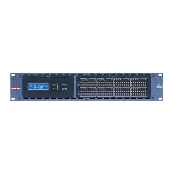
The SC 32 / SC 64 has a total analog I/O count of 32 (the SC 64 has 64), configurable in banks of eight. Eight analog input cards and eight analog output cards facilitate five different fully loaded configurations (nine for the SC 64). -
Page 7: Philosophy - Sc 32 / Sc 64
Device Window below). Device Presets A Device Preset is a snapshot of the current state of the SC 32 or SC 64. It includes the parameter values of all of the Processing Modules in the current configuration. Device Presets are managed from the Device Window using the Preset bar (see Device Window). - Page 8 SC32/SC64 Help...
-
Page 9: Front Panel
SC 32 / SC 64 Front Panel Controls/LEDs - SC 32 / SC 64 Front Panel LCD Display Gives information relating to network configuration, current time and date, HiQnet Node Address, SC firmware version and device status Page / Select Buttons... - Page 10 SC32/SC64 Help...
-
Page 11: Back Panel
SC 32 / SC 64 Back Panel Back Panel Connections - SC 32 / SC 64 Card Slots Ethernet Connectivity RS-232 Connectivity ZC Inputs Option Slots Control Inputs Relay Input OPTO Connection Logic Outputs Power Input Option Slots High-speed Option Slots accommodating high-bandwidth networked audio option... - Page 12 Opto-isolator conducts when device is powered and functioning correctly Logic Outputs Allow SC 32 / SC 64 to control up to six LED's or relays Ethernet Connectors Ethernet connectors for SC 32 / SC 64 configuration, control and monitoring as...
-
Page 13: Card Slots - Sc 32 / Sc 64
Configurable in banks of 8, the SC 32 and 64 provide up to 32 and 64 channels of audio respectively. Eight card slots facilitate five different fully loaded configurations (nine in the SC 64). The Analog Input card accommodates a wide range of sources with mic/line switching and phantom power per input. - Page 14 SC32/SC64 Help Card Types - SC 32 / SC 64 The SC 32/64 accepts Analog Input and Analog Output cards, carrying 8 channels per card. I/O Card Type Indication Analog Input LED/Connector - Green Analog Output LED/Connector - Orange Digital* Input LED/Connector - Blue (coming soon)
- Page 15 The dbx SC 32 and SC 64 Analog Input and Analog Output Cards are designed to populate any of the four or eight card slots on the dbx SC 32 and SC 64 devices respectively. These analog cards enable dbx SC devices to receive microphone / line level signals and send line level signals.
- Page 16 SC32/SC64 Help Analog Output Card: Connector 1 • Balanced / Unbalanced Audio, Channel 1 - Line Balanced / Unbalanced Audio, Channel 2 - Line Connector 2 • Balanced / Unbalanced Audio, Channel 3 - Line Balanced / Unbalanced Audio, Channel 4 - Line...
-
Page 17: Ethernet Connectivity - Sc 32 / Sc 64
Ethernet Connectivity - SC 32 / SC 64 Ethernet Connectors Ethernet connectors for SC 32 / SC 64 configuration, control and monitoring as well as integration of third party control systems using IP control (Integrated Ethernet switch allows daisy-chaining of devices within a rack). -
Page 18: Connectivity - Sc 32 / Sc 64
SC32/SC64 Help RS-232 Connectivity - SC 32 / SC 64 RS-232 Port Serial port for integration with third party control systems. -
Page 19: Zc Inputs 1-6 And 7-12 - Sc 32 / Sc 64
SC 32 / SC 64 ZC Inputs 1-6 and 7-12 - SC 32 / SC 64 ZC Ports Allow connection of up to 12 ZC controllers (six per port) for control of HiQnet parameters. -
Page 20: Option Slots - Sc 32 / Sc 64
SC32/SC64 Help Option Slots - SC 32 / SC 64 Option Slots High-speed Option Slots accommodating high-bandwidth networked audio option cards. (coming soon) SC 32 - One Option Slot SC 64 - Two Option Slots... -
Page 21: Control Inputs - Sc 32 / Sc 64
SC 32 / SC 64 Control Inputs - SC 32 / SC 64 Control Inputs Allows up to eight contact closures for control of HiQnet™ parameters. -
Page 22: Relay Input - Sc 32 / Sc 64
SC32/SC64 Help Relay Input - SC 32 / SC 64 Relay Integrated relay with Normally Open (NO) and Normally Closed (NC) terminals driven from HiQnet™ parameters. -
Page 23: Opto Connection - Sc 32 / Sc 64
SC 32 / SC 64 OPTO Connection - SC 32 / SC 64 Opto Opto-isolator conducts when device is powered and functioning correctly. -
Page 24: Logic Outputs - Sc 32 / Sc 64
SC32/SC64 Help Logic Outputs - SC 32 / SC 64 Logic Outputs Allow SC 32 / SC 64 to control up to six LEDs or relays. -
Page 25: Power Input - Sc 32 / Sc 64
SC 32 / SC 64 Power Input - SC 32 / SC 64 Power Connector IEC power connector. -
Page 26: Hardware
SC32/SC64 Help Hardware Spec Sheet - SC 32 / SC 64 FRONT PANEL INDICATORS Per channel: 48V (yellow), CLIP (red), SIGNAL (green) Per 8 channel bank: IN (green), OUT (orange), D-IN (blue), D-OUT (yellow), SYNC (green) Other: 16x2 LCD display, PAGE button (orange), SELECT button (green), CLIP (red),... - Page 27 SC 32 / SC 64 -90 dBu unweighted, 20 Hz - 20 kHz Dynamic Range: 113 dB "A" weighted, 20 Hz - 20 kHz 110 dB unweighted, 20 Hz - 20 kHz CMRR: > 40 dB typical, >50 dB at 1 kHz EIN: <...
- Page 28 SC32/SC64 Help Dynamic Range: 112 dB "A" weighted 109 dB unweighted, 20 Hz - 20 kHz D/A Latency: 10.4/Fs SYSTEM PERFORMANCE Dynamic Range: 110 dB "A"weighted 107 dB unweighted, 20 Hz to 20 kHz Frequency Response: 20 Hz - 20 kHz, +0/-0.5 dB THD+N: 0.0045% 0 dBu input, 1 kHz, 0 dB input gain 0.0065% 0 dBu input, 20 Hz - 20 kHz, 0 dB input gain...
- Page 29 ZONE CONTROLLER INPUTS Connectors: RJ-45 Number: 2 connectors with 6 channels per connector for a total of 12 inputs Usage: For use with dbx ZC wall controllers LOGIC OUTPUTS Connector: Phoenix/Combicon, 3.5mm pitch Number: Logic Output Voltage: 0 or +5 V unloaded...
- Page 30 SC32/SC64 Help RELAY CONTACT CLOSURE Connector: Phoenix/Combicon, 3.5mm pitch Contacts: Common (C), Normally Open (NO), Normally Closed (NC) Contact Rated Load: 0.3A at 125VAC, 1A at 30VDC WATCHDOG OUTPUT Connector: Phoenix/Combicon, 3.5mm pitch Type: Opto-isolated Output Current: 14 mA max Withstanding Voltage: 80 V max (off) Series Impedance:...
- Page 31 Systems exposed to these conditions should be inspected more frequently. Fan replacement can be performed either at the factory or by an experienced technician in the field. Please contact dbx Technical Support for more information on purchasing replacement parts or product service.
-
Page 32: Device Window - Sc 32 / Sc 64
The Preset Tool located directly below the Menu Bar is used to Store and Recall Presets to and from the SC device. Processing Modules Each Processing Module in the signal path of the SC 32 / SC 64 is displayed as... - Page 33 SC 32 / SC 64 an icon in the Device Window. These icons are designed to give a representation of the processing that is occurring. Processing can be broken down into Input and Output processing. Input Processing The input processing consists of a router, a delay, a 4-band parametric equalizer, a gate and two insert positions.
-
Page 34: Right Click Device Window Menu - Sc 32 / Sc 64
SC32/SC64 Help Right Click Device Window Menu - SC 32 / SC 64 When the user right clicks on the toolbar of the Device Window , the following menu appears Copy allows the user to copy all the settings within a particular Device Window... -
Page 35: Menus - Sc 32 / Sc 64
SC 32 / SC 64 Menus - SC 32 / SC 64 Menus - SC 32 / SC 64 At the top of the Device Window are the available menus. File Edit View Tools Help Selecting one of the above menus will open a menu of options within that menu. - Page 36 SC32/SC64 Help File Menu - SC 32 / SC 64 The File menu allows user access to store and recall program files. Open allows you to open Device Files. Save allows you to save Device Files. Close will close the Device Window.
- Page 37 SC 32 / SC 64 Edit Menu - SC 32 / SC 64 The Edit menu allows copy and paste functions.
- Page 38 SC32/SC64 Help View - SC 32 / SC 64 The View menu allows the user to dock windows including the Device Window. While docked, the individual menus are selected using tabs across the top. Click the view link on the menu bar.
- Page 39 SC 32 / SC 64 This can be helpful when switching from editor to editor during programming.
- Page 40 SC32/SC64 Help Tools Menu - SC 32 / SC 64 Tools - SC 32 / SC 64 The Tools Menu located on the Menu bar of the device view (or the main venue view when the device is docked) contains most of the tools needed to configure your device.
- Page 41 Card Configuration allows you to specify the input/output card configuration of an offline SC 32 or SC64. Peripheral Configuration allows you to choose the Zone Controllers, Control Inputs, Logic Outputs and Relay use associated with the SC 32 and SC 64. Card Configuration Peripheral Configuration...
- Page 42 0 x 8, 0 x 16, 0 x 24 and 0 x 32. SC 64: 8 x 0, 8 x 8, 8 x 16, 8 x 24, 8 x 32, 8 x 40, 8 x 48, 8 x 56, 16 x 0, 16 x 8,...
- Page 43 The Card Configuration window contains card slot dropdown menus where you may choose the card that will be populated into the SC 32 and SC 64. The SC 32 will have Card Slots "A" through "D" available and the SC 64 will have Card Slots "A" through "H" available.
- Page 44 SC32/SC64 Help (NOTE: The factory will populate the cards with Inputs first starting in the Bottom Right physical card slot "A" and then populate the rest of the slots "B", "C" and "D" ending with output cards if used).
- Page 45 SC 32 / SC 64 Peripheral Configuration - SC 32 / SC 64 The SC 32 and SC 64 have a great number of peripheral device controls that may be used. These options include Zone Controllers (ZC), Control Inputs, Logic Outputs and a Relay connection.
- Page 46 SC32/SC64 Help The Peripheral Configuration window allows you to select the type of Zone Controllers that will be attached to the SC 32 and SC 64. The dropdown menu next to Type is where you choose the appropriate controller. Your options are as follows.
- Page 47 SC 32 / SC 64 Once you have selected the ZC Controller to be used, you may then name the control as seen below. There is a great deal of information available on the Zone Controller page in addition to the previously mentioned ZC Type and name.
- Page 48 Control Inputs The Control Inputs section allows you to name physical controls that will be connected to the SC 32 or SC 64. The physical connection on the back of the SC device is highlighted in yellow to the right as seen above.
- Page 49 Logic Outputs The Logic Outputs section allows you to name physical devices that will be controlled or triggered by the SC 32 or SC 64. The physical connection on the back of the SC device is highlighted in yellow to the right as seen above.
- Page 50 SC32/SC64 Help The Relay section allows you to name the Relay connection. The Relay will provide either an open or closed state when active. The physical connection on the back of the SC device is highlighted in yellow to the right as seen above. One relay is available.
- Page 51 SC 32 / SC 64 Wizards - SC 32 / SC 64 Wizards - SC 32 - SC 64 The Wizards menu is where you will go to set up all your processing for the SC 32 and SC 64.
- Page 52 The configuration of signal path and DSP processing modules are made easy through the use of Wizards. The Wizards are used to set up your SC 32 and SC 64. These Wizards provide a step-by-step approach to the configuration of hardware and naming, routing, organization and mixing of signals.
- Page 53 SC 32 / SC 64 Navigating the Processing Wizard Navigating the Processing Wizard is made easy through the Quick Links to the left side of the window or through the NEXT and BACK buttons located at the bottom of the Wizard Screen.
- Page 54 The configuration of signal path and DSP processing modules are made easy through the use of Wizards. The Wizards are used to set up your SC 32 and SC 64. These Wizards provide a step-by-step approach to the configuration of hardware and naming, routing, organization and mixing of signals.
- Page 55 SC 32 / SC 64 Navigating the Processing Wizard Navigating the Processing Wizard is made easy through the Quick Links to the left side of the window or through the NEXT and BACK buttons located at the bottom of the Wizard Screen.
- Page 56 SC32/SC64 Help Input Names and Routes - SC 32 / SC 64 To get to the Input Names and Routes section of the Processing Wizard, click on the Input Names and Routes quick link or click on the Next button.
- Page 57 SC 32 / SC 64 With the Input Route Selection window open, select one of the available input channels as the source for the selected DSP channel. (Note: Only channels associated with an input card will appear. Ex; there is one analog input card loaded.
- Page 58 SC32/SC64 Help Input Groups - SC 32 / SC 64 To get to the Input Groups section of the Processing Wizard, click on the Input Groups quick link or click on the Next button until the Groups option is selected under Inputs.
- Page 59 SC 32 / SC 64 To rename a group you will click once on that groups name. In the example below I have clicked once on Group A. The group name will highlight and you may start typing your replacement name for that group.
- Page 60 SC32/SC64 Help Then click on either the up or down arrow to move the group up and down in the list. Moving DSP input channels to another Group One you have named your inputs, the new name will appear as an input channel within a group.
- Page 61 SC 32 / SC 64 One Group Added.
- Page 62 SC32/SC64 Help Channels one (Channel 1) and ten (Channel 10) moved to the new group.
- Page 63 SC 32 / SC 64...
- Page 64 SC32/SC64 Help Input Inserts - SC 32 / SC 64 To get to the Input Inserts section of the Processing Wizard, click on the Input Inserts quick link or click on the Next button until the Inserts option is selected under Inputs.
- Page 65 SC 32 / SC 64 1) AFS (Advanced Feedback Suppression) 2) Auto Gain Control 3) Compressor 4) De-Esser 5) 12-Band Notch Filter 6) 12-Band Parametric EQ 7) Sub-Harmonic Synthesizer Once you have selected a Processing Module insert for channel one (1), you may click on the Fill Down button to use the same Processing Module insert for any channels that follow within that group.
- Page 66 SC32/SC64 Help Mixers - SC 32 / SC 64 To get to the Mixers section of the Processing Wizard, click on the Mixers quick link or click on the Next button until the Mixers option is selected. Mixers are used to select multiple sources, set levels and create priority overrides that will be routed to an output channel or multiple output channels.
- Page 67 SC 32 / SC 64 With your mixer added and named, you may click on the AFS check box to add AFS post-processing if needed. The Available Resources information will keep you updated with the number of Mono Mixers and AFS inserts available for use.
- Page 68 SC32/SC64 Help You may therefore have up to 12 Mono Mixers and 8 AFS algorithms in an SC 32 16x16 or 24 Mono Mixers and 16 AFS Inserts in an SC 64 32x32. Removing a Mixer To remove a Mixer, select the mixer to be removed by clicking on it in the list.
- Page 69 SC 32 / SC 64 Output Names and Routes - SC 32 / SC 64 To get to the Output Names and Routes section of the Processing Wizard, click on the Output Names and Routes quick link or click on the Next button until the Names and Routes option is selected under Outputs.
- Page 70 SC32/SC64 Help With the output Route Selection window open, select one of the available Analog Inputs, DSP Inputs or Mixers to be routed to the output channel. With your source channel selected you may click on the OK button to assign the source or cancel to exit without making a change.
- Page 71 SC 32 / SC 64 You may choose one of the following crossover types. 1x1 (mono) 1x2 (mono bi-amp) 1x3 (mono tri-amp) or 1x4 (mono quad-amp)
- Page 72 SC32/SC64 Help Output Groups - SC 32 / SC 64 To get to the Output Groups section of the Processing Wizard, click on the Output Groups quick link or click on the Next button until the Groups option is selected under Outputs.
- Page 73 SC 32 / SC 64 Renaming a Group To rename a group you will click once on that group's name. In the example above I have clicked once on Group C. The group name will highlight and you may start typing your replacement name for that group.
- Page 74 SC32/SC64 Help To move a DSP output channel to another group, click and drag that channel from one group to the next. You may wish to reorder the DSP output channels within a group as well. You may do this by dragging the DSP output channel to another location within the group to create any channel order required for best use.
- Page 75 SC 32 / SC 64 Channel 65 and Channel 70 moved to the new group.
- Page 76 SC32/SC64 Help...
- Page 77 SC 32 / SC 64 Output Inserts - SC 32 / SC 64 To get to the Output Inserts section of the Processing Wizard, click on the Output Inserts quick link or click on the Next button until the Inserts option is selected under Outputs.
- Page 78 SC32/SC64 Help 1) Wire (default) 2) Amb. Noise Comp. (Ambient Noise Compensation) 3) Auto-Warmth 4) Auto Gain Control 5) Gain You will choose Output Insert Processing Modules in groups as you did with the Input Inserts. Once you choose an Output Insert Processing Module, you may click on the Fill Down button to populate remaining inserts with the insert that you have chosen for the first channel within the group.
- Page 79 The configuration of Zone Controllers (ZCs) is made easy through the use of the Zone Controller Wizard. The Wizards represent an easy way to set up your SC 32 and SC 64. These Wizards are designed to guide you step-by-step through the selection, options, connection and DIP switch assignment for each Zone Controller.
- Page 80 SC32/SC64 Help Please see the following sections for programming ZC Controllers. Navigating the ZC Controller Wizard Zone Controller Options...
- Page 81 SC 32 / SC 64 Navigating the ZC Wizard - SC 32 / SC 64 Navigating the Zone Controller Wizard is made easy through the Quick Links to the left side of the window or through the NEXT and BACK buttons located at the bottom of the Wizard Screen.
- Page 82 SC32/SC64 Help When you have completed any or all sections of this Wizard and wish to implement the changes made simply press the FINISH button located at the bottom right of the Zone Controller Wizard window. This will save your design to either an offline version of your device or load it straight into an online device.
- Page 83 SC 32 / SC 64 2) Name - This is where the name of this ZC Controller, specified within the Peripheral Wizard, is displayed. Ex: Room 1 Volume. 3) Action - The Action dropdown is where you will choose the action that the ZC Controller will complete when adjusted.
- Page 84 SC32/SC64 Help ZC-2 ZC-3 ZC-4 ZC-Fire ZC-6 ZC-7 ZC-8 ZC-9...
- Page 85 SC ZC Options - SC 32 / SC 64 SC ZC Options - SC 32 / SC 64 The SC 32 and SC 64 may use a wide array of external controls. One of the options is the ZC or Zone Controller.
- Page 86 ZC-2 This remote device provides computer programmable rotary volume and push- button mute control for the dbx DriveRack 260, 220i, 4800, ZonePRO™ and SC devices. The remote device has DIP switches allowing identification with connection to the processing device via CAT 5 cable on RJ-45 connectors. Seen here is the ZC-2 and ZC-2-EU.
- Page 87 ZC-4 The remote device provides programmable program selection via contact closures for the dbx DriveRack 4800, ZonePRO™ and SC devices. The remote device provides programmable source selection, page assignment, or scene selection. The remote has DIP switches allowing identification with connection to the processing device via CAT 5 cable on RJ-45 connectors.
- Page 88 SC32/SC64 Help ZC-FIRE The remote device provides either output muting or programmable scene selection. Connection to the fire safety system shall be either through a relay or directly to the control voltage output. The remote device has DIP switches allowing identification with connection to the processing device via CAT 5 cable on RJ-45 connectors.
- Page 89 SC 32 / SC 64 ZC-6 The remote device provides computer programmable push-button up/down volume control. The remote device has DIP switches allowing identification with connection to the processing device via CAT 5 cable on RJ-45 connectors. Seen here is the ZC-6 and ZC-6-EU.
- Page 90 SC32/SC64 Help ZC-7 The remote device provides preset selection or programmable push-to-talk page assignment. The remote device has DIP switches allowing identification with connection to the processing device via CAT 5 cable on RJ-45 connectors. Seen here is the ZC-7 and ZC-7-EU.
- Page 91 SC 32 / SC 64 ZC-8 The remote device provides both programmable push-button up/down volume control, and programmable rotary switch source selection. The remote device has DIP switches allowing identification with connection to the processing device via CAT 5 cable on RJ-45 connectors. Seen here is the ZC-8 and ZC-8-EU.
- Page 92 SC32/SC64 Help ZC-9 The remote device provides programmable 8 position source selection. The remote device has DIP switches allowing identification with connection to the processing device via CAT 5 cable on RJ-45 connectors. Seen here is the ZC-9 and ZC-9-EU.
- Page 93 The remote device provides up to 6 RJ-45 input jacks for "Home Run" or parallel wiring configurations. The remote device has one output RJ-45 jack for connection to the dbx device. The ZC-BOB is designed to allow longer cable lengths to multiple controllers. Seen here is the ZC-BOB.
- Page 94 SC32/SC64 Help...
- Page 95 SC 32 / SC 64 ZC1 - SC 32 / SC 64 The ZC-1 controller is the most commonly used controller and is used for volume control of an input mic or line or output zone. You can see below that a ZC-1 has already been configured in the Tools- >Hardware Configuration->->Peripheral Configuration Wizard and is listed as 1:...
- Page 96 SC32/SC64 Help Click on the NEXT button or on the 1: ZC-1 link to the left. The 1: ZC-1 window will appear as seen below. In the main right section of the window you will see the following. 6) Type - This is the ZC Controller that is attached to the 1: ZC-1 port. 7) Name - This is where the name of this ZC Controller, specified within the Peripheral Wizard, is displayed.
- Page 97 SC 32 / SC 64 Controller may take. These are driven by the type of Controller. The ZC-1 will only allow Actions as listed below. a. Gain - Adjust level 9) Below this section is a Gain Assignments section. When you click on Add/Remove, the following window will appear.
- Page 98 SC32/SC64 Help ZC2 - SC 32 / SC 64 The ZC-2 controller is a commonly used control for volume control and mute of an input (mic or line) or output zone. You can see below that a ZC-2 has already been configured in the Tools- >Hardware Configuration->Peripheral Configuration Wizard and is listed as 2:...
- Page 99 SC 32 / SC 64 Click on the NEXT button or on the 2: ZC-2 link to the left. The 2: ZC-2 window will appear as seen below. In the main right section of the window you will see the following.
- Page 100 SC32/SC64 Help 13) Action - The Action dropdown is where you will choose the action that the ZC Controller will complete when adjusted. There are several actions that a ZC Controller may take. These are driven by the type of Controller. The ZC-2 will only allow Actions as listed below.
- Page 101 SC 32 / SC 64 ZC3 - SC 32 / SC 64 The ZC-3 controller is used to select sources, Device Presets, Panel Presets,Venue Recalls and for page steering. You can see below that a ZC-3 has already been configured in the Peripheral Configuration Wizard and is listed as 3: ZC-3 below.
- Page 102 SC32/SC64 Help Click on the NEXT button or on the 3: ZC-3 link to the left. The 3: ZC-3 window will appear as seen below. In the main right section of the window you will see the following. 1) Type - This is the ZC- Controller that is attached to the 3: ZC-3 port. 2) Name - This is where the name of this ZC Controller, specified within the Peripheral Wizard, is displayed.
- Page 103 SC 32 / SC 64 3) Action - The Action dropdown is where you will choose the action that the ZC Controller will complete when adjusted. There are several actions that a ZC Controller may take. These are driven by the type of Controller. The ZC-3 will only allow Actions as listed below.
- Page 104 SC32/SC64 Help You will now choose a destination (or multiple destinations) where a Source will be routed. Clicking on the Add/Remove button will bring up the following screen.
- Page 105 SC 32 / SC 64 Select the Destinations from the list to which the Source will be routed. Click on OK to save changes. From the Source Assign section you will now click on the Source Assign button as seen below.
- Page 106 SC32/SC64 Help DSP Inputs • Mixers • Action: Actions Select When Actions Select is listed in the Action Dropdown Menu, the following screen will display.
- Page 107 SC 32 / SC 64 You will now choose an action to be taken when in the ZC-3 is switched through between "a" and "d". Click on the button to the right of each letter to open the Action Select Editor.
- Page 108 SC32/SC64 Help The Action Select Editor allows you to name your Action List, provide a Description and Add and Remove Actions. The Add and Remove buttons allow you to Add actions and Remove them as needed. The Move Up and Move Down Buttons allow you to reorder the Actions within the list.
- Page 109 SC 32 / SC 64 In this case I am going to choose a Panel Preset. Please see Panel Preset to create Panel Presets. The Select Panel Preset window opens. You may now select the Panel and the Panel Preset that will be recalled when the ZC-3 is changed between positions "A"...
- Page 110 SC32/SC64 Help Click on OK and your Action is set. Complete the preceding steps for actions in the "B", "C" and "D" positions.
- Page 111 SC 32 / SC 64 ZC4 - SC 32 / SC 64 The ZC-4 controller is used to select sources, Device Presets, Panel Presets,Venue Recalls and for page steering. You can see below that a ZC-4 has already been configured in the Peripheral Configuration Wizard and is listed as 4: ZC-4 below.
- Page 112 SC32/SC64 Help Click on the NEXT button or on the 4: ZC-4 link to the left. The 4: ZC-4 window will appear as seen below. In the main right portion of the window you will see the following. In the main right section of the window you will see the following. 7) Type - This is the ZC Controller that is attached to the 4: ZC-4 port.
- Page 113 SC 32 / SC 64 8) Name - This is where the name of this ZC Controller, specified within the Peripheral Wizard, is displayed. Ex: Room 1 Source. 9) Action - The action dropdown is where you will choose the action that the ZC Controller will complete when adjusted.
- Page 114 SC32/SC64 Help You will now choose a destination (or multiple destinations) where a Source will be routed. Clicking on the Add/Remove button will bring up the following screen.
- Page 115 SC 32 / SC 64 Select the Destinations from the list to which the Source will be routed. Click on OK to save changes. From the Source Assign section you will now click on the Source Assign button as seen below.
- Page 116 SC32/SC64 Help If DSP Output is selected for Router Type you will get the following options: Analog Inputs • DSP Inputs • Mixers • Action: Actions Select When Actions Select is listed in the Action Dropdown Menu, the following screen will display.
- Page 117 SC 32 / SC 64 You will now choose an Action to be taken when the ZC-4 is switched through between "a" and "p" via binary contact closure. Click on the button to the right of each letter to open the Actions Select Editor.
- Page 118 SC32/SC64 Help The Actions Select Editor allows you to name your Action List, provide a Description and Add and Remove Actions. The Add and Remove buttons allow you to Add actions and Remove them as needed. The Move Up and Move Down Buttons allow you to reorder the Actions within the list.
- Page 119 SC 32 / SC 64 In this case I am going to choose a Panel Preset. Please see Panel Preset to create Panel Presets. The Select Panel Preset window opens. You may now select the Panel and the Panel Preset that will be recalled when the ZC-4 is changed between positions "a"...
- Page 120 SC32/SC64 Help Click on OK and your action is set. Complete the preceding steps for actions in the remaining positions.
- Page 121 SC 32 / SC 64 ZCFIRE - SC 32 / SC 64 The ZC-FIRE controller is used for either output muting or programmable preset selection. Connection to the fire safety system shall be either through a relay or directly to the control voltage output .
- Page 122 SC32/SC64 Help Click on the NEXT button or on the 5: ZC-FIRE link to the left. The 5: ZC-FIRE window will appear as seen below. In the main right portion of the window you will see the following. 13) Type – This is where the name of this ZC Controller, specified within the Peripheral Wizard, is displayed.
- Page 123 SC 32 / SC 64 14) Action – The Action dropdown is where you will choose the Action that the ZC Controller will complete when adjusted. There are several actions that a ZC Controller may take. These are driven by the type of Controller. The ZC-FIRE will only allow Actions as listed below.
- Page 124 SC32/SC64 Help ZC6 - SC 32 / SC 64 The ZC-6 controller is commonly used for volume control of an input (mic or line) or output zone. You can see below that a ZC-6 has already been configured in the Peripheral Configuration Wizard and is listed as 6: ZC-6 below.
- Page 125 SC 32 / SC 64 Click on the NEXT button or on the 6: ZC-6 link to the left. The 6: ZC-6 window will appear as seen below. In the main right section of the window you will see the following.
- Page 126 SC32/SC64 Help 19) Action - The Action dropdown is where you will choose the Action that the ZC Controller will complete when adjusted. There are several actions that a ZC Controller may take. These are driven by the type of Controller. The ZC-6 will only allow Actions as listed below.
- Page 127 SC 32 / SC 64 ZC7 - SC 32 / SC 64 The ZC-7 controller is used for preset recall or page steering control of an input mic or line to an output zone. You can see below that a ZC-7 has already been configured in the Peripheral Configuration Wizard and is listed as 7: ZC-7 below.
- Page 128 SC32/SC64 Help Click on the NEXT button or on the 7: ZC-7 link to the left. The 7: ZC-7 window will appear as seen below. In the main right section of the window you will see the following. 1) Type – This is the ZC Controller that is attached to the 7: ZC-7 port. 2) Name –...
- Page 129 SC 32 / SC 64 3) Action – The Action dropdown is where you will choose the Action that the ZC Controller will complete when adjusted. There are several actions that a ZC Controller may take. These are driven by the type of Controller. The ZC-7 will only allow Actions as listed below.
- Page 130 SC32/SC64 Help This window allows you to choose a Device Preset, Panel Preset or Venue Recall to occur when selected. Multiple Actions can be assigned to a single button press or release. See the following sections for more information Creating a Panel Preset Creating a Device Preset...
- Page 131 SC 32 / SC 64 ZC8 - SC 32 / SC 64 The ZC-8 controller is used to select sources, Device Presets, Panel Presets, and Venue Recalls via a four position rotary control and input, mixer or output zone volume via up/down volume buttons.
- Page 132 SC32/SC64 Help Click on the NEXT button or on the 8: ZC-8 link to the left. The 8: ZC-8 window will appear as seen below. In the main right section of the window you will see the following. 4) Type - This is the ZC Controller that is attached to the 8: ZC-8 port. 5) Name - This is where the name of this ZC Controller, specified within the Peripheral Wizard, is displayed.
- Page 133 SC 32 / SC 64 6) Action - The Action dropdown is where you will choose the action that the ZC Controller will complete when adjusted. There are several actions that a ZC Controller may take. These are driven by the type of Controller. The ZC-8 will only allow Actions as listed below.
- Page 134 SC32/SC64 Help 9) Destination Selection - This control allows you to choose where you are routing the assigned Source. Multiple destinations can be selected. 10) Source Assignment - This section determines what will be routed to the selected destination(s). Action: Input Select When Input Select is listed in the Action dropdown list, the following screen will display.
- Page 135 SC 32 / SC 64 You will now choose a destination (or multiple destinations) where a Source will be routed. Clicking on the Add/Remove button will bring up the following screen. Select the Destinations from the list to which the Source will be routed.
- Page 136 SC32/SC64 Help If DSP Input is selected for Router Type you will get the following options: DSP Inputs • If DSP Output is selected for Router Type you will get the following options: Analog Inputs • DSP Inputs • Mixers •...
- Page 137 SC 32 / SC 64 You will now choose an action to be taken when in the ZC-8 is switched through between "a" and "d". Click on the button to the right of each letter to open the Action Select Editor.
- Page 138 SC32/SC64 Help The Actions Select Editor allows you to name your Action List, provide a Description and Add and Remove Actions. The Add and Remove buttons allow you to Add actions and Remove them as needed. The Move Up and Move Down Buttons allow you to reorder the Actions within the list.
- Page 139 SC 32 / SC 64 In this case I am going to choose a Panel Preset. Please see Panel Preset to create Panel Presets. The Select Panel Preset window opens. You may now select the Panel and the Panel Preset that will be recalled when the ZC-8 is changed between positions "A"...
- Page 140 SC32/SC64 Help Click on OK and your Action is set. Complete the preceding steps for actions in the "B", "C" and "D" positions.
- Page 141 SC 32 / SC 64 ZC9 - SC 32 / SC 64 The ZC-9 controller is used to select sources/presets and may be used for page steering. You can see below that a ZC-9 has already been configured in the Hardware Peripherals Configuration wizard and is listed as 9: ZC-9 below.
- Page 142 SC32/SC64 Help Click on the NEXT button or on the 9: ZC-9 link to the left. The 9: ZC-9 window will appear as seen below. In the main right section of the window you will see the following. 11) Type - This is the ZC Controller that is attached to the 9: ZC-9 port. 12) Name - This is where the name of this ZC Controller, specified within the Peripheral Wizard, is displayed.
- Page 143 SC 32 / SC 64 13) Action - The Action dropdown is where you will choose the Action that the ZC Controller will complete when adjusted. There are several actions that a ZC Controller may take. These are driven by the type of Controller. The ZC-9 will only allow Actions as listed below.
- Page 144 SC32/SC64 Help Select the Destinations from the list to which the Source will be routed. Click on OK to save changes. From the Source Assign section you will now click on the Source Assign Button as seen below. The Route Selection window will open. If DSP Input is selected for Router Type you will get the following options: DSP Inputs •...
- Page 145 SC 32 / SC 64 Action: Actions Select When Actions Select is listed in the Action Dropdown Menu, the following screen will display.
- Page 146 SC32/SC64 Help You will now choose an Action to be taken when in the ZC-9 is switched through between "a" and "h". Click on the button to the right of each letter to open the Actions Select Editor.
- Page 147 SC 32 / SC 64 The Actions Select Editor opens as seen below. The Actions Select Editor allows you to name your Action List, provide a Description and Add and Remove Actions. The Add and Remove Buttons allow you to Add Actions and Remove them as needed.
- Page 148 SC32/SC64 Help In this case I am going to choose a Panel Preset. Please see Panel Preset to create Panel Presets. The Select Panel Preset window opens. You may now select the Panel and the Panel Preset that will be recalled when the ZC-9 is changed between positions "A"...
- Page 149 SC 32 / SC 64 Click on OK and your action is set. Complete the preceding steps for actions in the remaining positions.
- Page 150 The ZC-BOB is non-programmable and non-powered. A single connection from a ZC to a dbx device allows up to a 1000 foot cable run to that ZC. ZC controllers may be linked from one to the next (or daisy chained in a single run) but this comes at a price.
- Page 151 Inputs, Logic Outputs and The Relay are made easy through the use of the GPIO Wizard. The Wizards represent an easy way to set up your SC 32 and SC 64. These Wizards are designed to guide you step-by-step through the selection and options for each GPIO.
- Page 152 SC32/SC64 Help Navigating the GPIO Wizard Navigating the GPIO Wizard is made easy through the Quick Links to the left side of the window or through the NEXT and BACK buttons located at the bottom of the Wizard Screen. Names of Control Inputs, Logic Outputs and the Relay configured in the Peripheral Configuration Wizard will be shown on the left side of the window.
- Page 153 SC 32 / SC 64 You may click on cancel at any time to exit out of the Wizard without saving any of the changes. When you have completed any or all sections of this Wizard and wish to implement the changes made simply press the FINISH button located at the bottom right of the GPIO Wizard window.
- Page 154 SC32/SC64 Help In the main right section of the window you will see the following. Name - This is where the name of this Control Input, specified within the Peripheral Wizard, is displayed. Action - The Action dropdown is where you will choose the Action that the Control Input will complete when adjusted.
- Page 155 SC 32 / SC 64 Click on the NEXT button or on the first Logic Output link to the left. You may have already inserted Logic Output names in the Peripheral Configuration Wizard. (See Peripheral Configuration) The Control Output 1 window will appear as seen below.
- Page 156 SC32/SC64 Help Click on the NEXT button or on each subsequent Logic Output link to the left to configure the remaining Logic Outputs. Click on the NEXT button or on the Relay link to the left. You may have already inserted a Relay name in the Peripheral Configuration Wizard.
- Page 157 SC 32 / SC 64 Subscription - Selects 'on/off' parameters to control the Relay. Click on the FINISH button to implement the changes.
- Page 158 SC32/SC64 Help Utilities - SC 32 / SC 64 The Utilities section of the SC 32 and SC 64 allows you to adjust, set and monitor a number of items. When the SC 32 and SC 64 are discovered by System Architect, they will automatically detect certain items within the device that will be displayed in Utilities.
- Page 159 SC 32 / SC 64 Overall Status Click on the Overall Status link. The Overall Status section allows you to see the current status of the following. 1) Audio Router 2) System Software 3) Ethernet 4) TCP/IP 5) All Systems...
- Page 160 SC32/SC64 Help Card Status Click on the Card Status link. The Card Status section allows you to see the current status of the following. 1) Audio Card A 2) Audio Card B 3) Audio Card C 4) Audio Card D These will all show a pass (default when offline) or fail status.
- Page 161 These will all show a pass (default when offline) or fail status. The DSP Status section will only report status of DSP per device selected. A through D for the SC 32 and A through H for the SC 64. Time Settings Click on the Time Settings link.
- Page 162 SC32/SC64 Help 2) Timezone. Clicking on the Timezone allows you to choose the country or part of the world that the install exists in. 3) Automatically adjust for Daylight Savings Time. Choosing this option will allow the SC device to change the current time and date based on the location in the world.
- Page 163 SC 32 / SC 64 Input Card Setup - SC 32 / SC 64 The Input Card Setup section of the Tools Menu for the SC 32 and SC 64 allows you to adjust Analog Input Gain, Input High Pass frequency, Signal Generator level and Sine Wave Generator Frequency.
- Page 164 SC32/SC64 Help This window contains a tab at the top of the page for each of the Analog Input cards loaded into the device. Input Channel Source Selection Each channel contains a dropdown menu that selects the Analog Source or a Signal Generator consisting of a SineWave, Pink Noise or White Noise generator.
- Page 165 SC 32 / SC 64 Controls available when Analog Source is selected.. 1) Analog Input Gain - this is the level of gain imposed on the input signal 2) High Pass Frequency - this is the lowest frequency that will pass forward to other DSP object from the input forward.
- Page 166 Priority Mix Controls - SC 32 / SC 64 The Priority Mix Controls section of the Tools Menu for the SC 32 and SC 64 allows you to adjust the nine (9) levels of priority override ducking used in the mixers of the SC 32 and SC 64.
- Page 167 SC 32 / SC 64 The Priority Mix Controls are used to set a global priority setting to be used by all mixers. Each Priority Level can have a different Depth, Attack, Hold and Release. As Priorities are assigned within each channel of the Priority Mixer the...
- Page 168 I/O Card Metering - SC 32 / SC 64 The I/O Card Metering section of the Tools Menu for the SC 32 and SC 64 allows you to see the input and output levels for each card loaded into the SC 32 and SC 64.
- Page 169 SC 32 / SC 64 Each tab of the I/O Card Meters window will show the 8 meters associated with that Input or Output card.
- Page 170 SC32/SC64 Help Help - SC 32 / SC 64 The Help file is the most complete way to find information on topics for control and programming. Click on the help menu option. From this menu you may choose the following.
-
Page 171: Device Presets - Sc 32 / Sc 64
SC 32 / SC 64 Device Presets - SC 32 / SC 64 A Device Preset is a snapshot of the current state of the SC 32 / SC 64. It includes the parameter values of all of the Processing Modules in the current configuration. -
Page 172: Processing Modules Sc 32 / Sc 64
SC32/SC64 Help Processing Modules SC 32 / SC 64 Processing Modules - SC 32 / SC 64 The SC 32 and SC64 are preconfigured architecture digital matrix processors. They have input processing with two configurable insert positions, a central matrix/mixer section and output processing with one configurable insert position. - Page 173 SC 32 / SC 64 brings up the Gate editor The table below shows the available insert Processing Modules for the input and output insert positions.
- Page 174 SC32/SC64 Help...
- Page 175 Input Editors - SC 32 / SC 64 Input Editors - SC 32 / SC 64 Processing in the SC 32 / SC 64 can broken into two distinct sections, Input and Output. Input Processing includes everything in the signal path before Mid Mixer/Router.
- Page 176 SC32/SC64 Help Input Gate (GATE) Input Inserts (INS1, INS2)
- Page 177 SC 32 / SC 64 Input Router - SC 32 / SC 64 Router - The Input Router allows you to adjust Source Gain for each channel signal path. Input Router editor: To configure this section, select Tools > Wizards > Processing Wizard.
- Page 178 SC32/SC64 Help Click on the Names and Routes link (under Inputs) to configure Routes and Channel Labels.
- Page 179 SC 32 / SC 64 Input Delay - SC 32 / SC 64 The input delay section is used to time align or delay input signals as needed. When the icon below is double clicked the window below will appear and allow for quick access for input signal delay settings.
- Page 180 SC32/SC64 Help Input 4-Band Parametric EQ - SC 32 / SC 64 4-Band Parametric EQ - This 4-band Parametric Equalizer offers adjustment of all the "parameters" of the filter; these parameters include Type, Frequency, Gain, and "Q". This lets you control the amplitude of each band as well as shift the center frequency and adjust the bandwidth of the filter.
- Page 181 SC 32 / SC 64 Filter Enable Button - This button provides individual on/off control of each PEQ filter. Freq Fader - This fader allows the user to select the center frequency of a Bell PEQ filter or the corner frequency of a Shelf filter.
- Page 182 SC32/SC64 Help Input Gate - SC 32 / SC 64 Gate - A fixed "infinite" downward expansion ratio. Used extensively for controlling unwanted noise, such as preventing "open" microphones from introducing extraneous sounds into an audio system. When the incoming audio signal drops below the user set-point (the threshold point) the expander prevents any further output by reducing the gain to "zero".
- Page 183 SC 32 / SC 64 Max Atten. Fader - This fader sets the amount of maximum attenuation applied to the signal once it has fallen below the Threshold. Attack Fader - This fader sets the time it takes for the volume of the sound to go from attenuated its original level.
- Page 184 SC32/SC64 Help Input DSP Inserts - SC 32 / SC 64 Input Inserts - SC 32 / SC 64 The following icons, when configured through the Processing Wizard, will appear on the control panel. When you double click the Processing Module icon on the Device Window, the editor for the DSP function will open.
- Page 185 SC 32 / SC 64...
- Page 186 SC32/SC64 Help Auto Gain Control - SC 32 / SC 64 Automatic Gain Control - The AGC is used to keep the average level of a signal at a constant level. High level signals are reduced by a fast limiter to prevent distortion by clipping.
- Page 187 SC 32 / SC 64 Window Fader - This fader adjusts the size of the Window around the target. Decreasing the size of the Window maintains tighter control of the signal, while opening the Window up provides less control. Attack Fader - This fader sets the length of time after a signal crosses the Threshold that gain or gain reduction will be applied.
- Page 188 SC32/SC64 Help Advanced Feedback Suppression - SC 32 / SC 64 AFS - The SC 32 / SC 64 offers the dbx exclusive Advanced Feedback Suppression (AFS™) algorithm as a Processing Module. This employs Precision Frequency Detection to find the exact center of the feedback down to one- hundredth of a Hertz (0.01Hz).
- Page 189 SC 32 / SC 64 sensitive. In Fixed mode, once filters are set they remain stored as part of the program until reset. Fixed mode is typically used before the performance without any input signal. Live Mode - When the mode is set to Live, the algorithm updates only the live filters.
- Page 190 SC32/SC64 Help Input Compressor - SC 32 / SC 64 Compressor - The Compressor Processing Module is used to reduce the dynamic range of the signal passing through it. This is normally done through the use of a VCA (Voltage Controlled Amplifier), whose gain is a function of a control voltage applied to it.
- Page 191 SC 32 / SC 64 2dB over the threshold the Compressor will reduce the gain with a resulting signal that is 1dB over the threshold. For light compression, choose a lower ratio, while heavy compression requires a higher ratio. A setting of Inf:1 makes the Compressor act as a limiter.
- Page 192 SC32/SC64 Help Input De-Esser - SC 32 / SC 64 De-Esser - The De-Esser Processing Module is ideal for removing unwanted vocal sibilance. On/Off Button - Turns the De-Esser on or off; when in the Off position the algorithm is bypassed in the signal chain.
- Page 193 SC 32 / SC 64...
- Page 194 SC32/SC64 Help Input SubHarmonic Synthesizer - SC 32 / SC 64 Sub-Harmonic Synthesizer - The Sub-Harmonic Synthesizer Processing Module has been specifically optimized to enhance Bass audio material. On/Off Button - Turns the Sub-Harmonic Synthesizer Processing Module on and off; when in the Off position, the signal path bypasses this algorithm.
- Page 195 SC 32 / SC 64 Input 12-band Notch Filter - SC 32 / SC 64 12-Band Notch Filter - The 12-Band Notch Filter Processing Module is the perfect tool for removing very specific undesirable frequencies that may appear in the signal. With Q up to 128 and the ability to cut by up to 36 dB, the 12-Band Notch Filter can provide extremely surgical frequency band removal.
- Page 196 SC32/SC64 Help Gain Fader - Sets the level of the selected Notch Filter. Set to +6dB to help find unwanted feedback, then set to -3dB to -36dB to remove. Q Fader - Selects the Q or bandwidth of the selected Notch Filter.
- Page 197 SC 32 / SC 64 Input 12-Band PEQ - SC 32 / SC 64 12-Band PEQ Filter - This 12-band Parametric Equalization (PEQ) Filter offers adjustment of all the "parameters" of the filter; these parameters include Type, Frequency, Gain, and Q. This lets you control the amplitude of each band as well as shift the center frequency and adjust the bandwidth of the filter.
- Page 198 SC32/SC64 Help Filter Select 1-12 - This allows the user to select a filter to work with. Filter Enable Button - This button provides individual on/off control of each PEQ filter. Freq Fader - This fader allows the user to select the center frequency of a bell PEQ filter or the corner frequency of a shelf filter.
- Page 199 SC 32 / SC 64 Wire (input) - SC 32 / SC 64 “Wire” is the default setting within the Processing Wizard for input inserts. When selected, audio passes through the insert unaffected.
- Page 200 Output Editors - SC 32 / SC 64 Output Editors - SC 32 / SC 64 Processing in the SC 32 / SC 64 can be broken into two distinct sections, Input and Output. Output Processing includes everything in the signal path after the Input Delay.
- Page 201 SC 32 / SC 64 Output Bandpass Filter Crossover (BPF) Output EQ (PEQ) Output Limiter (LIM) Output Delay (DLY)
- Page 202 SC32/SC64 Help Output Router - SC 32 / SC 64 The Output Router is the position where you will select whether you will select between discrete signals or the output of a Mid Mixer. Router - The Output Router allows you to specify which of the input or Mid Mixer Output signals will be sent to the output or output group if crossed over.
- Page 203 SC 32 / SC 64 Click on the Names and Routes link (under Outputs) to configure Routes, Crossover types, and Output Channel Labels.
- Page 204 SC32/SC64 Help Output DSP Inserts - SC 32 / SC 64 Output DSP Inserts - SC 32 / SC 64 The following icons when selected in the configuration wizard will appear on the control panel. When you double click the icon on the control panel an edit window for the DSP function will open and the parameters are available.
- Page 205 SC 32 / SC 64 . . . or select the Output DSP Inserts link.
- Page 206 SC32/SC64 Help...
- Page 207 SC 32 / SC 64 Wire (output) - SC 32 / SC 64 "Wire" is the default setting within the Processing Wizard for output inserts. When selected, audio passes through the insert unaffected.
- Page 208 SC32/SC64 Help Ambient Noise Compensation - SC 32 / SC 64 Ambient Noise Compensation (ANC) is a Processing Module that allows the level of zone outputs to track the ambient noise level, monitored through a microphone and microphone input. This feature is particularly well-suited to applications such as retail environments where the volume of the audio system can be matched automatically to the number of shoppers and their associated noise level.
- Page 209 SC 32 / SC 64 AutoWarmth - SC 32 / SC 64 AutoWarmth® is used to compensate for the natural loss in low frequency sensitivity at lower volumes. Based on the Fletcher-Munson Equal Loudness Curves this psychoacoustic algorithm provides automatic bass compensation dependant on signal level.
- Page 210 SC32/SC64 Help Auto Gain Control - SC 32 / SC 64 Automatic Gain Control - The AGC is used to keep the average level of a signal at a constant level. High level signals are reduced by a fast limiter to prevent distortion by clipping.
- Page 211 SC 32 / SC 64 Window Fader - This fader adjusts the size of the Window around the target. Decreasing the size of the Window maintains tighter control of the signal, while opening the Window up provides less control. Attack Fader - This fader sets the length of time after a signal crosses the Threshold that gain or gain reduction will be applied.
- Page 212 SC32/SC64 Help Gain - SC 32 / SC 64 Gain is used to increase the output volume of a signal. Fader - This fader increases or decreases the output volume. Mute Button - This button mutes the signal when engaged, and un-mutes the...
- Page 213 SC 32 / SC 64 Output Bandpass Filter/Crossover - SC 32 / SC 64 Bandpass Filter (BPF) - The Bandpass Filter (BPF) is a collection of filters and gain elements that can be used to frequency limit the outputs. By combining a Highpass and Lowpass filter you can create a Bandpass filter that will only allow the prescribed frequency bandwidth through the filter.
- Page 214 Polarity (+ / -) Button - This button sets whether the output signal will have a positive or negative output polarity. Said differently, changing from positive to negative will result in a positive voltage on the input of the SC 32 / SC 64 to result in a backward movement of the speaker cone.
- Page 215 SC 32 / SC 64 You may select from the following list the type of crossover filtering that best suits your needs. 1x1 mono • 1x2 (mono bi-amp) • 1x3 (mono tri-amp) • 1x4 (mono quad) •...
- Page 216 SC32/SC64 Help Output 6-Band PEQ - SC 32 / SC 64 6-Band Parametric EQ - This 6-band Parametric Equalizer offers adjustment of all the "parameters" of the filter; these parameters include Type, Frequency, Gain, and "Q". This lets you control the amplitude of each band as well as shift the center frequency and adjust the bandwidth of the filter.
- Page 217 SC 32 / SC 64 Filter Select 1-6 - This allows the user to select a filter to work with. Filter Enable Button - This button provides individual on/off control of each PEQ filter. Freq Fader - This fader allows the user to select the center frequency of a bell PEQ filter or the corner frequency of a shelf filter.
- Page 218 SC32/SC64 Help Output Limiter - SC 32 / SC 64 Limiter - Signal processor used to Limit the dynamic range of the signal passing through it. This is normally done through the use of a VCA (Voltage Controlled Amplifier), whose gain is a function of a control voltage applied to it.
- Page 219 SC 32 / SC 64 PeakStopPlus® On/Off - The first stage of PeakStopPlus is the Instantaneous Transient Clamp™ which clamps the signal with a soft logarithmic clamp function. This logarithmic function ensures that the signal will not exceed the level set by the PeakStopPlus Overshoot control by more than the Overshoot amount, and that it will not introduce harsh artifacts.
- Page 220 SC32/SC64 Help Output Delay - SC 32 / SC 64 Delay - Processing circuit used to delay one or more of the output signals by a controllable amount. This feature is used to correct for loudspeaker drivers that are mounted such that their points of apparent sound origin (not necessarily their voice coils) are not physically aligned.
-
Page 221: Creating Panel Presets - Sc 32 / Sc 64
SC 32 / SC 64 Creating Panel Presets - SC 32 / SC 64 A Panel Preset is a preset that recalls the state of one or more parameters on a single custom control panel. It is a snapshot of the values that are set on the panel. -
Page 222: Scheduling - Sc 32 / Sc 64
SC32/SC64 Help Scheduling - SC 32 / SC 64 The scheduler allows different types of events to be scheduled for specific times. These events recall information or perform a function either in the System Architect software or on the SC devices themselves. The events that can be scheduled include device presets, venue recalls and panel presets. -
Page 223: Wiring
Wiring Wiring - SC 32 / SC 64 Audio Cable Wiring All audio and control connections to the SC 64/ SC 32 are via 12 terminal female Phoenix Combicon-style 3.5mm connectors, which are supplied for making these connections. Audio Input and Output Wiring Convention... - Page 224 SC32/SC64 Help Control Inputs Used to connect contact closures. There are two common (ground) connections, labeled "C" to the left of the eight CONTROL INPUTS, and two reference voltage outputs, labeled "R" to the right of the eight CONTROL INPUTS. Relay Contacts Supports control of a voltage source and load that is AC, or supports control of a voltage source and load that is higher-current DC than is supported by the logic...
- Page 225 SC 32 / SC 64 relay) may be driven by connecting four outputs in parallel. This arrangement will develop 4V across a 500-Ohm coil, providing that all four outputs are made logic 1 simultaneously.
-
Page 226: Ethernet - Sc 32 / Sc 64
SC32/SC64 Help Ethernet - SC 32 / SC 64 Zone Controller Cat5 Cable The Zone Controllers may use standard Cat5 Cable. The pin configuration is shown below. The link buss cable uses the same straight through cable configuration as the Zone Controllers. -
Page 227: Zone Controllers - Sc 32 / Sc 64
SC 32 / SC 64 Zone Controllers - SC 32 / SC 64 Zone Controller Installation The installation of the Zone Controllers MUST be accomplished with the use of cable which is rated VW-1 or higher. Common NEC designations which meet this rating include: CMP, CMR, CMG, CM and CMX. - Page 228 SC32/SC64 Help RS-232 - SC 32 / SC 64 The serial (RS-232) connection to the SC 32 / SC 64 is made through a Null Modem cable. A straight-through serial (RS-232) cable will not work. Network connections made directly from the SC 32 / SC 64 must be made using...
-
Page 229: Zone Controller Distance Limitations - Sc 32 / Sc 64
SC 32 / SC 64 Zone Controller Distance Limitations - SC 32 / SC 64 All Zone Controllers can be wired serially or in parallel. As length increases, the total cable distance decreases. One controller can be wired with up to 1000 feet of cable, three controllers in series at 600 feet and six controllers in series at 300 feet total cable length. - Page 230 SC32/SC64 Help...
-
Page 231: Zone Controller Dip Switch - Sc 32 / Sc 64
SC 32 / SC 64 Zone Controller DIP Switch - SC 32 / SC 64 Zone Controller Wiring All Zone Controllers can be wired serially or in parallel. To wire in series, each Zone Controller must have an identification number (ID) chosen using the DIP switches on the side of the controller (see diagram A). - Page 232 SC32/SC64 Help To set up the ZCs, the System Architect GUI must be used. Open the GUI and click on ZC Wizard in the Tools menu. Select the type of ZC and the ID#. The ID numbers on the left side of the window correspond to the identification number set using the DIP switches on the individual zone controllers.