Table of Contents
Advertisement
Service Manual
CONTENTS
Laser beam safety precaution .......................................... 1
IC Block Diagram & Description ....................................... 1,9
Tuner Adjustments ........................................................... 2
Wiring Connection ........................................................... 3
Exploded View (Cabinet & Chassis) ................................ 4
Parts List .......................................................................... 6
Schematic Diagram .......................................................... 11
Wiring Diagram ............................................................... 16
Block Diagram .................................................................. rear
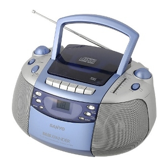
CD Portable Radio
Cassette Recorder
FILE NO.
MCD-ZX200F
(XE)
PRODUCT CODE No.
164 128 00
SM
REFERENCE No.
5810606
Advertisement
Table of Contents

Related Manuals for Sanyo MCD-ZX200F


Summary of Contents for Sanyo MCD-ZX200F
-
Page 1: Table Of Contents
FILE NO. CD Portable Radio MCD-ZX200F Service Manual (XE) Cassette Recorder PRODUCT CODE No. CONTENTS 164 128 00 Laser beam safety precaution .......... 1 IC Block Diagram & Description ........1,9 Tuner Adjustments ............2 Wiring Connection ............3 Exploded View (Cabinet & Chassis) ........ 4 Parts List ................ -
Page 2: Laser Beam Safety Precaution
LASER BEAM SAFETY PRECAUTION • Pickup that emits a laser beam is used on this CD section. CAUTION : USE OF CONTROLS OR ADJUSTMENTS OR PERFORMANCE OF PROCEDURES OTHER THAN THOSE SPECIFIED HEREIN MAY RESULT IN HAZARDOUS RADIATION EXPOSURE. CLASS 1 LASER PRODUCT CAUTION-INVISIBLE LASER RADIATION WHEN OPEN AND LUOKAN 1 LASERLAITE KLASS 1 LASERAPPARAT... -
Page 3: Tuner Adjustments
TUNER ADJUSTMENTS Use a plastic screw driver for adjustments. Adjust the intermediate frequency of AM and FM to the frequency of ceramic filter. Set of unit Supply voltage : DC 12.0V Speaker impedance : 8 ohms Standard output : 50 mW Function switch : RADIO a. -
Page 4: Wiring Connection
WIRING CONNECTION This is a basic wiring connection. - 3 -... -
Page 5: Exploded View(Cabinet & Chassis)
EXPLODED VIEW(CABINET & CHASSIS) : Not available as service parts. - 4 - - 5 -... -
Page 6: Parts List
PARTS LIST PARTS LIST REF.NO. PART NO. DESCRIPTION REF.NO. PART NO. DESCRIPTION 645 069 6763 FFC CABLE 18P, L0102 645 024 1031 FTZ COIL,BH-81228712 PRODUCT SAFETY NOTICE CTL CN703 TO CD DECK L0105 645 033 4757 AM COIL 645 069 6756 2P HSG, PC101 645 026 6676 PVC,PVC101 EACH PRECAUTION IN THIS MANUAL SHOULD BE FOLLOWED DURING SERVICING. - Page 7 IC BLOCK DIAGRAM & DESCRIPTION PARTS LIST CASS DECK MECHANISM ASSY IC903 LA6541 (CD Driver) IC101 LA1824 (Tuner) REF.NO. PART NO. DESCRIPTION 645 050 1814 CASS DECK MECHANISM Vref VIN4 VIN3 645 050 2101 ASSY,MOTOR 11k Ω 11k Ω 645 068 7976 ASSY,PINCH ROLLER PHASE GND2 Vcc2...
-
Page 8: Schematic Diagram
SCHEMATIC DIAGRAM (TUNER) IC BLOCK DIAGRAM & DESCRIPTION IC902 IC78601RE (ANALOG SIGNAL PROCESSOR) Pin Name Function PIN NAME Function *SEG6 The segment output (6) terminal. (The pull-up resister internal ) It is junction in unused time, 0 V defect detecting signal (DEF) input DEF1 terminal *SEG5... - Page 9 SCHEMATIC DIAGRAM (MAIN) This is a basic schematic diagram. - 12 - - 13 -...
- Page 10 SCHEMATIC DIAGRAM (CD) This is a basic schematic diagram. - 14 - - 15 -...
-
Page 11: Wiring Diagram
WIRING DIAGRAM (MAIN , POWER SUPPLY & CONTROL) POWER SUPPLY MAIN CONTROL This is a basic wiring diagram. - 16 - - 17 -... -
Page 12: Block Diagram
WIRING DIAGRAM (CD ) BLOCK DIAGRAM This is a basic block diagram. SANYO Electric Co., Ltd. Osaka, Japan This is a basic wiring diagram. May./ '04 Printed in Japan - 18 - - 19 -...