Advertisement
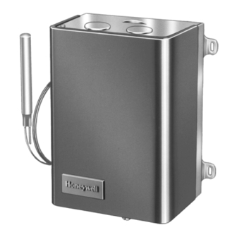
The L8151A is a remote bulb controller for use
with hydronic heating systems that include domes-
tic hot water service.
Provides high limit, low limit, and circulator control
for maintaining boiler temperatures.
Can provide multizone control by using a separate
thermostat and R845 Relay for each zone.
An internal transformer powers the thermostat cir-
cuit.
Triple Aquastat
Shielded capillary allows convenient mounting.
Consists of a diaphragm powerhead and micro switch
assembly that responds to temperature changes in
the boiler water.
CONTENTS
Specifications ................................................. 2
Ordering Information ..................................... 2
Installation ..................................................... 2
Operation and Settings ................................... 5
Checkout ......................................................... 6
J. H. • Rev. 1-95 • ©Honeywell Inc. 1995 • Form Number 60-2553-3
1
L8151A
Relay
®
60-2553-3
Advertisement

Related Manuals for Honeywell TRIPLEAQUASTAT L8151A


Summary of Contents for Honeywell TRIPLEAQUASTAT L8151A
-
Page 1: Table Of Contents
CONTENTS Specifications ... 2 Ordering Information ... 2 Installation ... 2 Operation and Settings ... 5 Checkout ... 6 J. H. • Rev. 1-95 • ©Honeywell Inc. 1995 • Form Number 60-2553—3 L8151A Relay ® 60-2553—3... -
Page 2: Specifications
Honeywell Inc., 1885 Douglas Drive North Minneapolis, Minnesota 55422-4386 In Canada—Honeywell Limited/Honeywell Limitée, 35 Dynamic Drive, Scarborough, Ontario M1V 4Z9. International Sales and Service Offices in all principal cities of the world. Manufacturing in Australia, Canada, Finland, France, Germany, Japan, Mexico, Netherlands, Spain, Taiwan, United Kingdom, U.S.A. - Page 3 6-1/8 (156) 4-1/2 (114) 13/16 (21) 1. Screw the well into the boiler, tank, or pipe tapping. 3-5/16 2-3/6 (84) (56) 2. Insert the bulb into the well, pushing tubing until bulb bottoms in well. Avoid making sharp bends or kinks in the M8892 capillary.
- Page 4 L8151A INSTALLATION Fig. 3—Remote bulb installation. JAWS SPREAD JAWS TO FIT OVER RIDGE ON SPUD OF WELL SCREWDRIVER INSERT— MOUNTING CLAMP DRAW MOUNTING CLAMP TUBING 4. With part no.121371AA Retainer Clamp attached to well spud (be sure jaws of clamp hook over ridge at end of spud, as shown at points A), adjust tubing to fit through retainer clamp groove, as shown at point B.
-
Page 5: Operation And Settings
HIGH LIMIT The high limit opens and turns off the burner when the water temperature reaches the setpoint. The high limit automatically resets after the water temperature drops past the setpoint and through the 10°F (6°C) differential. WARNING CAN CAUSE PROPERTY DAMAGE, SEVERE INJURY OR DEATH. -
Page 6: Checkout
Fig. 7. Put the system into operation and observe each function through at least one complete cycle. Be sure the control operates as intended. Automation and Control Solutions Honeywell International Inc. 1985 Douglas Drive North Golden Valley, MN 55422 60-2553—3 THERMOSTAT ANTICIPATOR Set the thermostat heat anticipator at 0.2A.