Honda EW171 Owner's Manual
Generator/welder
Hide thumbs
Also See for EW171:
- Owner's manual (55 pages) ,
- Owner's manual (50 pages) ,
- Owner's manual (55 pages)
Table of Contents
Advertisement
Quick Links
Advertisement
Table of Contents

Related Manuals for Honda EW171


Summary of Contents for Honda EW171
- Page 2 The aenerator if misused. Do notexpose not let the generator get wet, and do not operate it with wet hands. is a potential source of electrical shock the generator to moisture, rain or snow. Do...
- Page 3 Thank you for purchasing a Honda generator/welder. the best results from your new generator/welder manual contains the information on how to do that; please read it carefully. This owner’s manual describes the operation and maintenance of the EWI 71 Honda generator/welder. latest product information available at the time of printing.
-
Page 4: Table Of Contents
CONTENTS SAFETY ... Safety Label Locations ... Safety Information ... COMPONENT IDENTIFICATION CONTROLS ... Engine Switch ... Recoil Starter ... Fuel Valve ... Choke Rod ... Circuit Breaker ... Oil Alert System ... system ... Auto-throttle AC/DC (Weld) Selector Switch ..i ... Welding Cable Terminal ... - Page 5 MAINTENANCE.. Schedule ... Maintenance Tool Kit ... Engine Oil Change ... Air Cleaner Service ... Fuel Sediment Cup Cleaning Spark Plug Service ... Spark Arrester Maintenance TRANSPORTING/STORAGE TROUBLESHOOTING.. WIRING DIAGRAM ... SPECIFICATIONS OF OPTIONAL PARTS ... INSTALLATION WARRANTY SERVICE ... INDEX ...
-
Page 6: Safety
SAFETY SAFETY LABEL LOCATION These labels warn you of potential hazards that can cause serious injury. Read them carefully. If a label comes off or becomes hard to read, contact your Honda Generator dealer for a replacement. DO NOT USE INDOORS. EXHAUST GAS CONTAINS POISONOUS h ‘WARNING CARBON MONOXIDE. - Page 7 EW 17 1 ” HONDA MOTOR CO., LTD. CAUTION BE SURE TO FILL CRANKCASE WITH RECOMMENDED BEFORE USING. FOR DETAILED EXPLANATION. SEE THE OWNER’S MANUAL. CURRENT RANGE 50 - 170 Amps DC RATED CURRENT 130 A -26.5 V-DC > MAD IN JAPAN AC OUTPUT...
-
Page 8: Safety Information
SAFETY INFORMATION Honda generator/welder are designed to give safe and dependable service if operated according to instructions. Read and understand this owner’s manual before operating your generator/welder. being familiar with your generator’s controls, and by observing safe operating procedures. Operator Responsibility Know how to stop the generator/welder Understand the use of all generator/welder and connections. - Page 9 Fire and Burn Hazards The exhaust system gets hot enough to ignite some materials. Keep the generator/welder and other equipment during operation. Do not enclose the generator/welder Keep flammable materials away from the generator/welder. The muffler becomes very hot during operation and remains hot for a while after stopping the engine.
-
Page 10: Component Identification
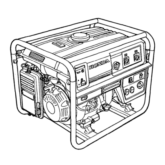
COMPONENT IDENTIFICATION FUEL GAUGE ENGINE SWITCH CHOKE ROD FUEL VALVE CLEANER RECOIL STARTER GRIP AUTO THkOlTLE SWITCH WELDING CURRENT ADJUSTMENT ENGINE SERIAL NUMBER KNOB WELDING CABLE ‘ITCH Ai2 RECEPTACLES... - Page 11 FUEL TANK CAP SERIAL NUMBER MU\FFLER Record the engine and frame serial numbers for your future reference. Refer to these serial numbers when oidering parts, and when making technical or warranty inquiries (see page 41) Frame serial number: Engine serial number:...
-
Page 12: Controls
CONTROLS Engine Switch To start and stop the engine. Switch position: OFF: To stop the engine. To run the engine. Recoil Starter To start the engine, pull the starter grip lightly until resistance is felt, then pull Do not allow the starter to snap back against the engine. Return it gently to prevent damage to the starter. -
Page 13: Fuel Valve
Fuel Valve The fuel valve is located between the fuel tank and carburetor. When the valve fuel lever is in the ON position, fuel is allowed to flow from the fuel tank to the carburetor. Be sure to return the fuel lever to OFF position after stopping the engine. -
Page 14: Circuit Breaker
Circuit Breaker The circuit breaker will automatically significant overload of the generator at the receptacle. If the circuit breaker is switched OFF automatically, and does not exceed the rated load capacity of the circuit before switching the circuit breaker ON again. The circuit breaker may be used to switch the generator power ON or OFF. -
Page 15: Auto-Throttle System
Auto-throttle System The auto-throttle system automatically reduces engine speed when AC loads are turned off or disconnected, are turned on or reconnected, or DC welding is resumed, the engine returns to the rated speed. AUTO: Recommended noise levels when no load is applied to the generator/welder. OFF: The auto-throttle system does not operate. -
Page 16: Welding Cable Terminal
Welding Cable Terminal A separate terminal is provided for connection to the welding cable. Failure to use the proper gauge cable may lead to painful burns and/or damage to equipment. See table on page 18. Welding Current Adjust System For best results, it is essential that current be adjusted properly according to the thickness of the materials to be welded and the method of welding. -
Page 17: Generator Use
Connections to a Building’s Connections for standby power to a building’s electrical system must be made by a qualified electrician. The connection must isolate the generator power from utility power, and must comply with all applicable laws and electrical codes. Improper connections can allow electrical current from thegenerator lines. -
Page 18: Ac Operation
For continuous operation, do not exceed the rated load capacity (EW171: 4.0 KVA). In either case, be sure to consider the total power requirements of all connected appliances. -
Page 19: Welding
Welding Welding is potentially a very hazardous activity. It should only be attempted by a trained welder with a thorough proper welding techniques and safety procedures. follow the safety rules on pages 3,4 and 5 of this manual. 1. Put the Engine Switch in the OFF position. Turn the AC circuit breaker off and remove any plugs from the AC receptacles. -
Page 20: Welding Cable Selection
The duty cycle is the percentage of time that the welder can be operated in a given 10 minute period. For example, at a rated output of 130 amperes, the EW171 ‘s duty cycle is 50%. This means that at 130 amperes, welding can be performed for a total of 5 minutes out of every 10 minute period. -
Page 21: Polarity Selection
Polarity Selection The welding terminals are labeled I‘+” (positive) and “-‘I (negative). Changing the polarity of the cables will affect the weld. The correct polarity selection is dependent on the type of electrode you are using and the type of material you are welding;... -
Page 22: Auto-Throttle System
Auto-throttle system With the switch in the AUTO position, engine speed is automatically when ALL loads areturned OFF or disconnected. When appliances areturned ON or reconnected, the engine returnsto rated speed. In the OFF position, the auto-throttle system does not operate. The auto-throttle system will not respond to electrical loads of less than 1 ampere. -
Page 23: Preoperation Check
Engine oil riiimq Engine oil is a major factor affecting engine performance and service life. Non-detergent and are not recommended. Check the oil level BEFORE EACH USE with the generator on a level surface with the engine stopped. Use Honda 4-stroke equivalent high detergent,... -
Page 24: Fuel Recommendation
Fuel Recommendation 1. Check the fuel level gauge. 2. Refill the tank if the fuel level is low. Do not fill above the shoulder of the fuel strainer. Gasoline is extremely conditions. Refuel in a well-ventilated smoke or allow flames or sparks in the area where the engine is refueled or where gasoline is stored. - Page 25 Occasionally you may hear light “spark knock” or “pinging” (metallic rapping noise) while operating under heavy loads. This is no cause for concern. If spark knock or pinging occurs at a steady engine speed, under normal load, change brands of gasoline. authorized Honda generator dealer.
-
Page 26: Starting The Engine/Stopping The Engine
STARTING THE ENGINE/STOPPING THE ENGINE Starting the Engine 1. Make sure that the AC circuit breaker is in the OFF position, and that there are no welding cables attached to the DC terminals. The generator may be hard to start if a load is connected. 2. -
Page 27: Maintenance
Periodic maintenance welder in good operating condition. Perform the service and inspection at the intervals shown in the Maintenance Exhaust gas contains poisonous Shut off the engine before performing any maintenance. must be run, make sure the area is well ventilated. pmicq Use only genuine HONDA parts or their equivalent for maintenance or repair. -
Page 28: Tool Kit
Tool kit The tools supplied with the generator will help you to perform the owner maintenance procedures listed on the following page. Always keep this tool kit with the generator/welder. 10 x 12 mm WRENCH PLUG WRENCH HANDLE BAR SCREW DRIVER DRIVER HANDLE TOOL BAG... -
Page 29: Engine Oil Change
Engine oil change Drain the oil while the engine is warm to assure complete and rapid draining. 1. Remove the drain plug and sealing washer, oil filler cap, and drain the oil. 2. Install the drain plug and sealing washer. Tighten the plug securely. 3. -
Page 30: Air Cleaner Service
Air cleaner service A dirty air cleaner will restrict air flow to the carburetor. To prevent carburetor malfunction, service the air cleaner regularly. Service more frequently when operating the generator/welder Using gasoline or flammable solvent to clean the filter element can cause a fire or explosion. nonflammable solvent. -
Page 31: Fuel Sediment Cup Cleaning
Fuel Sediment Cup Cleaning The sediment cup prevents dirt or water which may be in the fuel tank from entering the carburetor. sediment cup should be cleaned. 1. Turn the fuel valve to the OFF position. Remove the sediment cup, O-ring, and filter. -
Page 32: Spark Plug Service
Spark Plug Service Recommended spark plugs: To ensure proper engine operation, the spark plug must be properly gapped and free of deposits. If the engine has been running, the muffler will be very hot. Be careful not to touch the muffler. Remove the spark plug cap. -
Page 33: Spark Arrester Maintenance
7. Check that the spark plug washer is in good condition, and thread the spark plug in by hand to prevent cross-threading. 8. After the spark plug is seated, tighten with a spark plug wrench to compress the washer. If installing a new spark plug, tighten l/2 turn after the spark plug seats to compress the washer. -
Page 34: Transporting/Storage
TRANSPORTING/STORAGE When transporting the generator/welder, valve OFF and keep the generator/welder vapor or spilled fuel may ignite. Contact with a hot engine or exhaust system can cause serious burns or fires. Let the engine cool before transporting the generator/welder. Take care not to drop strike the generator/welder place heavy objects on the generator/welders. - Page 35 1. Drain the carburetor by loosening the drain screw. Drain the gasoline into a suitable container. Gasoline is extremely conditions Perform this task in a well ventilated area with the engine stopped. Do not smoke or allow flames or sparks in the area during this procedure.
-
Page 36: Troubleshooting
TROUBLESHOOTING When the engine will not start: the engine? Be sure there is no spilled fuel around the spark plug. Spilled fuel may ignite. YEi5 Is the fuel reaching the carburetor? not start, take the gen- erator/welder to an authorized Honda (The oil alert lamp flashes when cranking the engine.) - Page 37 No electricity at the AC receptacles: Is the AC circuit break- , NO er ON When the welding arc is weak: 1 Is the cable size car- 1 NO rect? Is the proper electrode being used? DEFECTS w an authorized Honda Replace the electrical ap- pliance or equipment.
-
Page 38: Wiring Diagram
WIRING DIAGRAM L--..-- ---- --_-... -
Page 39: Specifications
AC output Rated Ampere Rated Output NOTE: Specifications are subject to change without notice. SPECIFICATIONS EW171 675 x 510 x 490 mm (26.6 x 20.1 x 19.3 in) 92 kg (202.8 lb) GX340Kl 4-stroke, overhead valve, single cylinder 337 cc (20.6 cu in) [82 x 64 mm (3.2 x 2.5 in)] 8.0 : 1... -
Page 40: Installation Of Optional Parts
INSTALLATION OF OPTIONAL PARTS Hanger Kit Installation 8 x 16 mm FLANGE BOLT (4) Position the hanger at the generator’s balance point, in the middle of the fuel tank. Fit the end tabs of the hanger through the bracket slots, and bolt the brackets to the hanger. - Page 41 4 Wheel Kit Installation 1. Install the four wheels on the axle shaft. 2. Install the axle assembly on the generator using four bolts and nuts. WHEEL SiOPPER NOTE: Install the shaft with wheel stopper facing engine side. Inside $ger Shorter...
- Page 42 2 Wheel kit Installation 1. Install the two wheels on the axle shaft. 2. Install the axle assembly on the generator using four bolts and nuts. 3. Install the two stands using four bolts and nuts. 4. Install right and left handles on the generator upper frame using brackets and six bolts.
-
Page 43: Warranty Service
Owner satisfaction Your satisfaction and goodwill are important to your dealer and to us. All Honda warranty details are explained in the Distributor’s Normally, any problems concerning dealer’s service department. If you have a warranty problem that has not been handled to your satisfaction, we suggest you take the following action: Discuss your problem with a member of dealership management. -
Page 44: Index
INDEX COMPONENT IDENTIFICATION CONTROLS ... AC/DC (Weld) Selector Switch ... system ... Auto-throttle Choke Rod ... Circuit Breaker ... Engine Switch ... Fuel Valve ... Oil Alert System ... Recoil Starter ... Welding Cable Terminal Welding Current Adjust System ... USE ... - Page 45 INDEX TRANSPORTING/STORAGE TROUBLESHOOTING.. WARRANTY SERVICE ... WIRING DIAGRAM ...
- Page 46 MEMO...