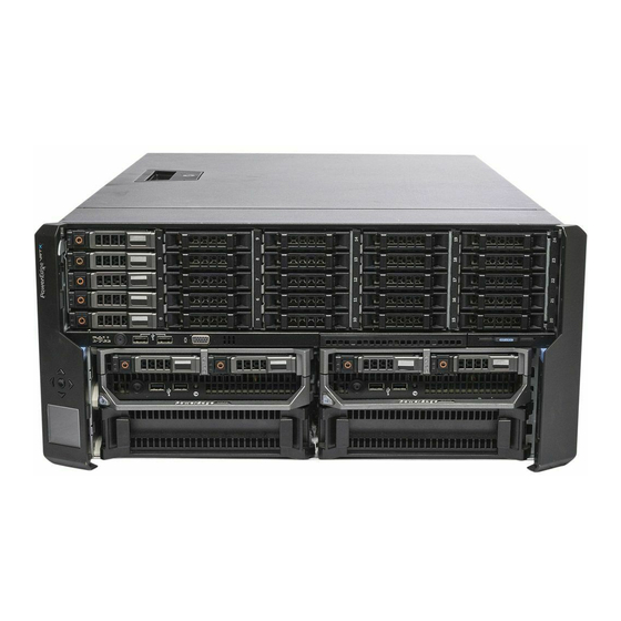
Dell PowerEdge VRTX Owner's Manual
Enclosure
Hide thumbs
Also See for PowerEdge VRTX:
- Reference manual (931 pages) ,
- User manual (193 pages) ,
- Owner's manual (143 pages)

Related Manuals for Dell PowerEdge VRTX


Summary of Contents for Dell PowerEdge VRTX
- Page 1 Dell PowerEdge VRTX Enclosure Owner's Manual Regulatory Model: E22S Regulatory Type: E22S001...
- Page 2 Copyright © 2014 Dell Inc. All rights reserved. This product is protected by U.S. and international copyright and intellectual property laws. Dell and the Dell logo are trademarks of Dell Inc. in the United States and/or other jurisdictions. All other marks and names ™...
-
Page 3: Table Of Contents
Contents 1 About Your System........................9 ................................9 Introduction ..........................9 Terms Used In The Document ..............................10 System Overview ................11 Server Module And Hard-Drive Numbering — Tower Mode ................16 Server Module And Hard-Drive Numbering — Rack Mode ........................20 Front-Panel Features And Indicators ..............................22 KVM Features... - Page 4 4 Installing Enclosure Components...................41 .............................. 41 Recommended Tools ............................. 41 Front Bezel (Optional) ..........................41 Installing The Front Bezel ..........................42 Removing The Front Bezel ............................42 System Feet—Tower Mode ..........................42 Removing The System Feet ..........................43 Installing The System Feet ......................43 Wheel Assembly (Optional)—Tower Mode ........................43 Installing The Wheel Assembly...
- Page 5 ............................71 Cooling-Fan Assembly ......................71 Removing The Cooling-Fan Assembly ....................... 73 Installing The Cooling-Fan Assembly ..............................73 Blower Modules ..........................73 Removing A Blower Module ..........................74 Installing A Blower Module ........................75 Removing The Blower Module Bay ........................75 Installing The Blower Module Bay ................................
- Page 6 .........................105 Storage Controller Indicators ..................106 Removing An Integrated Storage Controller Card ...................107 Installing An Integrated Storage Controller Card ..............................108 System Battery ........................108 Replacing The System Battery ..........................109 System Top And Base Covers ....................109 Removing The System Top And Base Covers ....................
- Page 7 ........................146 Troubleshooting The I/O Module 7 System Board Connectors.....................149 8 Technical Specifications....................... 153 ............................153 Enclosure Specifications ............................ 154 I/O Module Specifications ..........................154 Environmental Specifications 9 Getting Help..........................159 ..............................159 Contacting Dell ............................159 Quick Resource Locator .............................159 Documentation Feedback...
-
Page 9: About Your System
About Your System Introduction This document provides information on the Dell PowerEdge VRTX enclosure. Terms Used In The Document The following table describes the terms used in this document. Term Description Enclosure or chassis Refers to the VRTX enclosure. Server module(s) -
Page 10: System Overview
System Overview Your system includes up to four Dell PowerEdge M520 or M620 half-height server modules, two PowerEdge M820 full- height server modules, or a mix of the server module types. The server modules are specifically configured for the VRTX enclosure, and can be identified by a label marked PCIe on the server module. -
Page 11: Server Module And Hard-Drive Numbering - Tower Mode
Server Module And Hard-Drive Numbering — Tower Mode Figure 2. Half-Height Server Module and Hard-Drive Numbering — 2.5 Inch Hard-Drive Chassis server module numbering hard-drive numbering... - Page 12 Figure 3. Full-Height Server Module and Hard-Drive Numbering — 2.5 Inch Hard-Drive Chassis server module numbering hard-drive numbering...
- Page 13 Figure 4. Server Module (Half-Height and Full-Height Server Modules) and Hard-Drive Numbering — 2.5 Inch Hard-Drive Chassis server module numbering hard-drive numbering...
- Page 14 Figure 5. Half-Height Server Module and Hard-Drive Numbering — 3.5 Inch Hard-Drive Chassis server module numbering hard-drive numbering Figure 6. Full-Height Server Module and Hard-Drive Numbering — 3.5 Inch Hard-Drive Chassis server module numbering hard-drive numbering...
- Page 15 Figure 7. Server Module (Half-Height and Full-Height Server Modules) and Hard-Drive Numbering — 3.5 Inch Hard-Drive Chassis server module numbering hard-drive numbering...
-
Page 16: Server Module And Hard-Drive Numbering - Rack Mode
Server Module And Hard-Drive Numbering — Rack Mode Figure 8. Half-Height Server Module and Hard-Drive Numbering — 2.5 Inch Hard-Drive Chassis server module numbering hard-drive numbering... - Page 17 Figure 9. Full-Height Server Module and Hard-Drive Numbering — 2.5 Inch Hard-Drive Chassis server module numbering hard-drive numbering Figure 10. Server Module (Half-Height and Full-Height Server Modules) and Hard-Drive Numbering — 2.5 Inch Hard-Drive Chassis...
- Page 18 Figure 11. Half-Height Server Module and Hard-Drive Numbering — 3.5 Inch Hard-Drive Chassis server module numbering hard-drive numbering Figure 12. Full-Height Server Module and Hard-Drive Numbering — 3.5 Inch Hard-Drive Chassis server module numbering hard-drive numbering...
- Page 19 Figure 13. Server Module (Half-Height and Full-Height Server Modules) and Hard-Drive Numbering — 3.5 Inch Hard-Drive Chassis server module numbering hard-drive numbering...
-
Page 20: Front-Panel Features And Indicators
Front-Panel Features And Indicators Figure 14. Front-Panel Features And Indicators — 2.5 Inch Hard Drive Chassis... - Page 21 Figure 15. Front-Panel Features And Indicators — 3.5 Inch Hard Drive Chassis Item Indicator, Button, or Icon Description Connector USB connectors (2) Allows a keyboard and mouse to be connected to the system. LCD panel Provides system information and status and error messages to indicate when the system is operating correctly or when the system needs attention.
-
Page 22: Kvm Features
Item Indicator, Button, or Icon Description Connector 3.5 inch hard Up to twelve 3.5 inch hot- drive enclosure swappable hard drives. Information tag A slide-out label panel which allows you to record system information such as Service Tag, NIC, MAC address, the system electrical rating, and Worldwide Regulatory Agency marks. -
Page 23: Lcd Module
Drive-Status Condition Indicator Pattern Blinks green two Identifying drive or preparing for removal times per second Drive ready for insertion or removal NOTE: The drive status indicator remains off until all hard drives are initialized after the system is turned on. Drives are not ready for insertion or removal during this time. Blinks green, amber, Predicted drive failure and off... - Page 24 • Menus to configure the iDRAC in each server module. • Status information screens for each server module. • Status information screens for the modules installed in the back of the enclosure, including the I/O module, blower modules, CMC, KVM, and power supplies. •...
- Page 25 DVD Mapping From this screen, you can view the DVD to server mapping information, map another server to the DVD drive on the chassis, or unmap the existing connection. KVM Mapping Menu From this screen, you can view the KVM to server mapping information, map another server to the KVM, or unmap the existing connection.
-
Page 26: Back-Panel Features And Indicators
Back-Panel Features And Indicators Figure 18. Back-Panel Features and Indicators Item Indicator, Button, or Icon Description Connector PCIe expansion card slots Allows you to connect up to five low-profile PCI Express low-profile (5) expansion cards. PCIe expansion card slots Allows you to connect up to three full-height PCI Express full height (3) expansion cards. -
Page 27: Power Supply Indicators
Item Indicator, Button, or Icon Description Connector Power supply (PSU3) 1100 W AC Power supply (PSU1) 1100 W AC Power supply (PSU2) 1100 W AC Power Supply Indicators Each AC power supply has an illuminated translucent handle that serves as an indicator to show whether power is present or whether a power fault has occurred. -
Page 28: Blower Module Indicators
Blower Module Indicators Figure 20. Blower Module Indicators blower module power indicator blower module fault indicator The indicators provide the following information: Indicator Description Blower module Steady Green The blower module is receiving power. power indicator The blower module is not receiving power. Blower module fault Blinking Amber The blower module is in a fault condition. -
Page 29: I/O Module Indicators
Blinking Blue The CMC is identifying the I/O module. Blinking Amber The I/O module is in a fault condition. The I/O module is powered off, or booting is in progress. For more information, see the I/O module documentation at dell.com/poweredgemanuals. -
Page 30: Cmc Indicators
CMC Indicators Figure 22. CMC Indicators status/identification indicator (CMC 1) power indicator (CMC 1) power indicator (CMC 2) status/identification indicator (CMC 2) The CMC indicators on the back panel of the enclosure provide the following information: Indicator Description Power indicator Green The CMC is receiving power. -
Page 31: Cmc Fail-Safe Mode
Dell Chassis Management event. For more information on updating the CMC firmware, see the Controller for Dell PowerEdge VRTX User’s Guide at dell.com/esmmanuals. CMC error detection Chassis management resumes after the CMC resets or chassis fails over to the standby CMC. -
Page 32: System Messages
WARNING: See the safety and regulatory information that shipped with your system. Warranty information may be included within this document or as a separate document. Dell PowerEdge VRTX Getting Started Guide shipped with your system provides an overview of system features, •... -
Page 33: Quick Resource Locator
Use the Quick Resource Locator (QRL) to get immediate access to system information and how-to videos. This can be done by visiting dell.com/QRL or by scanning a model specific QR code located on your Dell PowerEdge system using your smartphone. You can also access your system information and how-to videos by scanning the following QR code. -
Page 35: Initial System Configuration
• Your system supports Dell PowerEdge M520, M620, and M820 server modules that are specifically configured for the enclosure, and can be identified by a label marked PCIe on the server module. If you install PowerEdge M520, M620, and M820 server modules that are not configured for the enclosure, an error message is displayed. For more... -
Page 36: Logging In To The Cmc
Dell Chassis Management NOTE: For a detailed description on configuring the CMC settings, see the Controller for Dell PowerEdge VRTX User’s Guide at dell.com/esmmanuals. Connect to the CMC IP address through the Web browser using the default logon credentials. The default user name is root and password is calvin. -
Page 37: Configuring Enclosure Components
RJ-45. The following conditions apply: • Dell PowerEdge M520 server module disables ports 3 and 4 when a pass-through module is installed. However, if you install a switch module, all four network ports on Fabric A are utilized. •... -
Page 38: Supported I/O Modules
Dell PowerEdge VRTX 1Gb R1-PT pass-through module • Dell PowerEdge VRTX 1Gb R1-2401 switch module NOTE: For more information on the I/O modules, see the I/O module's documentation at dell.com/ poweredgemanuals. Configuring Network Settings For The I/O Module You can specify the network settings for the interface used to manage the I/O module. -
Page 39: Managing Pcie Slots
The switches map the mezzanine cards to the PCIe slots on the enclosure's system board. There are five PCIe low profile slots on the system board and three full-height, full-length PCIe slots on the PCIe riser. All the PCIe slots can be mapped to the PCIe mezzanine cards on the server modules to provide I/O expansion for the system: PCIe mezzanine Fabric B and Fabric C cards on each server module are mapped to the PCIe switches which further map to the PCIe slots and the Shared PERC slots on the enclosure's system board. -
Page 40: Managing Chassis Storage
Dell Chassis Management For more information on managing the PCIe slots using the CMC web interface, see the Controller for Dell PowerEdge VRTX User’s Guide at dell.com/esmmanuals. Managing Chassis Storage The enclosure provides shared storage with single or dual Shared PERC/Expander configurations. The Shared PERC cards support Single Root Input Output Virtualization (SR-IOV) feature and enable the server modules to map to the local storage through the PCIe switches on the enclosure system board. -
Page 41: Installing Enclosure Components
Installing Enclosure Components WARNING: Whenever you need to lift the system, get others to assist you. To avoid injury, do not attempt to lift the system by yourself. WARNING: Exercise care when removing or installing components when the system is on, to avoid the risk of electric shock. -
Page 42: Removing The Front Bezel
Keeping the keylock pressed with the bezel key, rotate the keylock to the locked position. NOTE: The bezel key can be found taped to the inside of the bezel. Figure 25. Removing and Installing the Front Bezel release tab keylock front bezel bezel tabs Removing The Front Bezel... -
Page 43: Installing The System Feet
Remove the screws securing the system feet to the system base cover. Figure 26. Removing and Installing the System Feet system feet (4) screws (4) screw holes (4) system base cover Installing The System Feet Align the screw holes on the system feet with the screw holes on the system base cover. Install the screws to secure the system feet to the system base cover. - Page 44 NOTE: The front and back wheel plates are labeled. To reduce the chassis weight, remove the following (if required): a) Front bezel (if installed) b) Hard drives. See Removing A Hot-Swap Hard Drive. c) Server modules. See Removing A Server Module.
- Page 45 15. Route the power supply cables through the power cable retention bracket. Figure 27. Removing and Installing the Wheel Assembly hooks for the metal stands (4) metal stands (2) back wheel plate front wheel plate screws (2) tabs on system base cover (4)
-
Page 46: Removing The Wheel Assembly
Figure 28. Removing and Installing the Power Cable Retention Bracket chassis slots tabs on the power cable retention bracket (2) power cable retention bracket Removing The Wheel Assembly Remove any cables routed through the power cable retention bracket. Slide the power cable retention bracket to the right to unlock it. Holding it by the edges, pull the bracket out of the chassis slots and away from the chassis. -
Page 47: Opening And Closing The System
Damage due to servicing that is not authorized by Dell is not covered by your warranty. Read and follow the safety instructions that came with the product. -
Page 48: Closing The System
Damage due to servicing that is not authorized by Dell is not covered by your warranty. Read and follow the safety instructions that came with the product. -
Page 49: Hard Drives
NOTE: Components that are hot-swappable are marked orange and touch points on the components are marked blue. Figure 30. Inside the System cooling fans (6) cooling shroud CMC card indicators (2) chassis intrusion switch PCIe cage CMC cards (2) low profile expansion-card divider unit power distribution board bracket system base cover hard drives (25) -
Page 50: Removing A 2.5 Inch Hard-Drive Blank
NOTE: The following procedures apply to the hard drives in the enclosure. For server module-specific hard drives, see the server module's Owner's Manual at dell.com/poweredgemanuals. Removing A 2.5 Inch Hard-Drive Blank CAUTION: To maintain proper system cooling, all empty hard-drive slots must have hard-drive blanks installed. -
Page 51: Installing A 3.5 Inch Hard-Drive Blank
Figure 32. Removing and Installing a 3.5 Inch Hard-Drive Blank hard-drive blank release button Installing A 3.5 Inch Hard-Drive Blank If installed, remove the front bezel. Insert the hard-drive blank into the hard-drive slot until the release button clicks into place. If applicable, install the front bezel. -
Page 52: Installing A Hot-Swap Hard Drive
Damage due to servicing that is not authorized by Dell is not covered by your warranty. Read and follow the safety instructions that came with the product. -
Page 53: Removing A Hard Drive From A Hard-Drive Carrier
Removing A Hard Drive From A Hard-Drive Carrier Remove the screws from the slide rails on the hard-drive carrier. For the 2.5 inch hard drive, turn the hard-drive carrier upside down, and remove the screws from the side rails on the hard-drive carrier. -
Page 54: Installing A Hard Drive Into A Hard-Drive Carrier
Damage due to servicing that is not authorized by Dell is not covered by your warranty. Read and follow the safety instructions that came with the product. -
Page 55: Removing A Server Module
Removing A Server Module If installed, remove the front bezel. Turn off the server module using the operating system commands or the CMC. When a server module is powered off, its front-panel power indicator is off. Press the release button on the server module handle. Pull out the server module handle to unlock the server module from the enclosure. - Page 56 Install the I/O connector cover(s) over the I/O connector(s). Figure 36. Removing and Installing the I/O Connector Cover I/O connector cover NOTE: There are two I/O connector covers on the PowerEdge M820 server module.
-
Page 57: Configuring A Server Module
To configure a server module for the VRTX enclosure: Open the server module. For more information on opening a server module, see the server module Owner's Manual at dell.com/ poweredgemanuals. Remove any mezzanine cards installed in Fabric B and Fabric C slots of the server module. -
Page 58: Installing A Server Module
Install PCIe Mezzanine cards in the vacant Fabric B and Fabric C slots. For more information on installing the PCIe Mezzanine cards, see the server module Owner's Manual at dell.com/ poweredgemanuals. Ensure that no tools or parts are left inside the server module. -
Page 59: Removing The Server Module Partitions
Damage due to servicing that is not authorized by Dell is not covered by your warranty. Read and follow the safety instructions that came with the product. - Page 60 To remove the server module partition between Slots 1 and 3: a) Hold the release tab on the server module partition and pull it out from the chassis wall to disengage the locking tab from the slot on the chassis wall. b) Holding the release tab, pull the partition toward the front of the system until it stops sliding.
- Page 61 To remove the server module partition between Slots 2 and 4: a) Hold the release tab on the server module partition and pull it out from the chassis wall to disengage the locking tab from the chassis slot. b) Holding the release tab, pull the partition toward the front of the system until it stops sliding. The tabs on the partition move to unlock position.
-
Page 62: Installing The Server Module Partitions
Damage due to servicing that is not authorized by Dell is not covered by your warranty. Read and follow the safety instructions that came with the product. -
Page 63: Power Supplies
To install the server module partition between Slots 2 and 4: a) Angle the partition and slide it into the chassis. b) Align the tabs on the partition with the slots on the inner chassis wall and insert the tabs into the slots. c) Rotate the partition upward in the clockwise direction until the tabs on the other side of the partition engage with the slots on the metal partition. -
Page 64: Power Supply Blanks
Damage due to servicing that is not authorized by Dell is not covered by your warranty. Read and follow the safety instructions that came with the product. - Page 65 NOTE: In systems that ship with the wheel assembly, a power cable retention bracket is used to route the power cable from the power supply. Disconnect the power cable from the power source and the power supply you intend to remove. a) In systems without the wheel assembly installed, remove the power cable from the cable strap.
- Page 66 Figure 45. Securing the Power Cable (Without Wheel Assembly) power cable strap...
-
Page 67: Installing A Power Supply
Damage due to servicing that is not authorized by Dell is not covered by your warranty. Read and follow the safety instructions that came with the product. -
Page 68: Cooling Shroud
Damage due to servicing that is not authorized by Dell is not covered by your warranty. Read and follow the safety instructions that came with the product. -
Page 69: Installing The Cooling Shroud
Damage due to servicing that is not authorized by Dell is not covered by your warranty. Read and follow the safety instructions that came with the product. -
Page 70: Cooling Fans
Damage due to servicing that is not authorized by Dell is not covered by your warranty. Read and follow the safety instructions that came with the product. -
Page 71: Installing A Cooling Fan
Damage due to servicing that is not authorized by Dell is not covered by your warranty. Read and follow the safety instructions that came with the product. - Page 72 To reduce the chassis weight, remove the following (if required): a) hard drives b) server modules c) power supplies If applicable, rotate the system feet inward and lay the system on its side on a flat stable surface, with the cover release latch side on top.
-
Page 73: Installing The Cooling-Fan Assembly
Damage due to servicing that is not authorized by Dell is not covered by your warranty. Read and follow the safety instructions that came with the product. -
Page 74: Installing A Blower Module
Damage due to servicing that is not authorized by Dell is not covered by your warranty. Read and follow the safety instructions that came with the product. -
Page 75: Removing The Blower Module Bay
Damage due to servicing that is not authorized by Dell is not covered by your warranty. Read and follow the safety instructions that came with the product. -
Page 76: I/O Module
Damage due to servicing that is not authorized by Dell is not covered by your warranty. Read and follow the safety instructions that came with the product. -
Page 77: Installing The I/O Module
Damage due to servicing that is not authorized by Dell is not covered by your warranty. Read and follow the safety instructions that came with the product. - Page 78 11. Disconnect the power/data cable from the back of the optical drive. Note the routing of the power/data cable as you remove them from the system board and the optical drive. You must route these cables properly when you replace them to prevent them from being pinched or crimped. 12.
-
Page 79: Installing The Optical Drive
Damage due to servicing that is not authorized by Dell is not covered by your warranty. Read and follow the safety instructions that came with the product. -
Page 80: Cmc Card Indicators
Damage due to servicing that is not authorized by Dell is not covered by your warranty. Read and follow the safety instructions that came with the product. -
Page 81: Installing A Cmc Card
Damage due to servicing that is not authorized by Dell is not covered by your warranty. Read and follow the safety instructions that came with the product. -
Page 82: Removing The Pcie Cage Door
Damage due to servicing that is not authorized by Dell is not covered by your warranty. Read and follow the safety instructions that came with the product. -
Page 83: Installing The Pcie Cage Door
Damage due to servicing that is not authorized by Dell is not covered by your warranty. Read and follow the safety instructions that came with the product. - Page 84 12. Holding the PCIe cage by the slots, lift the cage up and away from the chassis. Figure 57. Removing and Installing the PCIe Cage metal standoffs (2) screws (2) release latch PCIe cage guide pin expansion-card riser connectors (2) metal tabs on the chassis (4) screw holes (2) bracket on chassis side...
-
Page 85: Installing The Pcie Cage
Damage due to servicing that is not authorized by Dell is not covered by your warranty. Read and follow the safety instructions that came with the product. -
Page 86: Expansion Card Operational Power Status
The following table provides guidelines for installing expansion cards to ensure proper cooling and mechanical fit. The expansion cards with the highest priority must be installed first using the slot priority indicated. All other expansion cards must be installed in card priority and slot priority order. Table 2. -
Page 87: Pcie Slot Indicators
Chassis Status Server Module Status Expansion Card Status NOTE: The system cover must be installed for the new expansion card to power on. NOTE: To verify if a PCIe slot is powered on, see PCIe Slot Indicators. PCIe Slot Indicators The expansion-card slots are warm-plug. -
Page 88: Removing A Low Profile Expansion Card
Damage due to servicing that is not authorized by Dell is not covered by your warranty. Read and follow the safety instructions that came with the product. -
Page 89: Installing A Low Profile Expansion Card
Damage due to servicing that is not authorized by Dell is not covered by your warranty. Read and follow the safety instructions that came with the product. -
Page 90: Removing The Low Profile Expansion Card Divider Unit
Damage due to servicing that is not authorized by Dell is not covered by your warranty. Read and follow the safety instructions that came with the product. -
Page 91: Installing The Low Profile Expansion Card Divider Unit
Damage due to servicing that is not authorized by Dell is not covered by your warranty. Read and follow the safety instructions that came with the product. -
Page 92: Removing A Full Height Expansion Card
Damage due to servicing that is not authorized by Dell is not covered by your warranty. Read and follow the safety instructions that came with the product. -
Page 93: Installing A Full Height Expansion Card
Damage due to servicing that is not authorized by Dell is not covered by your warranty. Read and follow the safety instructions that came with the product. -
Page 94: Removing The Full-Height Expansion-Card Divider Unit
Damage due to servicing that is not authorized by Dell is not covered by your warranty. Read and follow the safety instructions that came with the product. -
Page 95: Installing The Full Height Expansion Card Divider Unit
Damage due to servicing that is not authorized by Dell is not covered by your warranty. Read and follow the safety instructions that came with the product. -
Page 96: Removing The Expansion Card Riser
Damage due to servicing that is not authorized by Dell is not covered by your warranty. Read and follow the safety instructions that came with the product. - Page 97 14. Slide the expansion-card riser out of the PCIe cage. Figure 64. Removing and Installing the Expansion-Card Riser PCIe cage screw holes (6) expansion-card riser screws (6) Figure 65. Expansion-card Riser Connectors expansion-card connector (SLOT3) expansion-card connector (SLOT2) expansion-card connector (SLOT1) chassis intrusion switch power cable connector...
-
Page 98: Installing The Expansion Card Riser
Damage due to servicing that is not authorized by Dell is not covered by your warranty. Read and follow the safety instructions that came with the product. - Page 99 Open the PCIe cage door. Disconnect the 6-pin connectors of the auxiliary power cable from the power cable connectors on the double-wide PCIe cage. Disconnect the 8-pin connector of the auxiliary power cable from the power cable of the double-wide GPGPU card. Figure 66.
- Page 100 11. Remove the double-wide GPGPU card from the expansion-card connector on the riser, and slide it out of the double-wide PCIe cage. Figure 67. Removing and Installing a Double-Wide GPGPU Card tab on the double-wide PCIe cage double-wide GPGPU card bracket double-wide GPGPU card double-wide PCIe cage 12.
-
Page 101: Installing A Double-Wide Gpgpu Card
Damage due to servicing that is not authorized by Dell is not covered by your warranty. Read and follow the safety instructions that came with the product. - Page 102 11. Lower the double-wide GPGPU card into the double-wide PCIe cage and insert the card-edge connector firmly into the expansion-card connector on the riser, until the card is fully seated. The double-wide GPGPU card bracket aligns with the tab on the double-wide PCIe cage. Figure 68.
-
Page 103: Integrated Storage Controller Cards
15. Connect the two 6-pin connectors on the other end of the auxiliary power cable to the power cable connectors on the double-wide PCIe cage. Figure 69. Installing the Auxiliary Power Cable to the Power Cable Connectors 6-pin connector of the auxiliary power cable (2) power cable connectors on the double-wide PCIe cage auxiliary power cable... -
Page 104: Storage Controller Operational Power Status
Storage Controller Operational Power Status The following table provides information on the operational power status of the integrated storage controller card when: • the storage controller slot is mapped to multiple server modules • the system cover is installed Chassis Status Server Module Status (All Server Storage Controller Status Modules) -
Page 105: Storage Controller Indicators
Storage Controller Indicators Figure 70. Storage Controller Indicators power indicator on system board attention indicator on system board power indicator on storage controller card The storage controller indicators provide the following information: Indicator Description Power indicator on Steady Green The storage controller slot is receiving power. system board Blinking Green Hot swap operation is in progress and insertion or removal of the... -
Page 106: Removing An Integrated Storage Controller Card
Damage due to servicing that is not authorized by Dell is not covered by your warranty. Read and follow the safety instructions that came with the product. -
Page 107: Installing An Integrated Storage Controller Card
Damage due to servicing that is not authorized by Dell is not covered by your warranty. Read and follow the safety instructions that came with the product. -
Page 108: System Battery
Damage due to servicing that is not authorized by Dell is not covered by your warranty. Read and follow the safety instructions that came with the product. -
Page 109: System Top And Base Covers
Damage due to servicing that is not authorized by Dell is not covered by your warranty. Read and follow the safety instructions that came with the product. -
Page 110: Installing The System Top And Base Covers
Damage due to servicing that is not authorized by Dell is not covered by your warranty. Read and follow the safety instructions that came with the product. -
Page 111: Mounting Ears
Damage due to servicing that is not authorized by Dell is not covered by your warranty. Read and follow the safety instructions that came with the product. -
Page 112: Installing The Mounting Ears
Damage due to servicing that is not authorized by Dell is not covered by your warranty. Read and follow the safety instructions that came with the product. -
Page 113: Replacing The Lcd Module
Damage due to servicing that is not authorized by Dell is not covered by your warranty. Read and follow the safety instructions that came with the product. -
Page 114: Installing The Control Panel
Damage due to servicing that is not authorized by Dell is not covered by your warranty. Read and follow the safety instructions that came with the product. -
Page 115: Removing The Control Panel Board
Damage due to servicing that is not authorized by Dell is not covered by your warranty. Read and follow the safety instructions that came with the product. -
Page 116: Installing The Control Panel Board
Damage due to servicing that is not authorized by Dell is not covered by your warranty. Read and follow the safety instructions that came with the product. -
Page 117: Backplane Expander Boards
Damage due to servicing that is not authorized by Dell is not covered by your warranty. Read and follow the safety instructions that came with the product. -
Page 118: Installing A Backplane Expander Board
Damage due to servicing that is not authorized by Dell is not covered by your warranty. Read and follow the safety instructions that came with the product. -
Page 119: Hard-Drive Backplane
Damage due to servicing that is not authorized by Dell is not covered by your warranty. Read and follow the safety instructions that came with the product. - Page 120 13. Pull the backplane release pins in the direction of the system board and lift the backplane from the chassis. Figure 78. Removing and Installing the 2.5 inch (x25) Hard-drive Backplane hard-drive connectors (25) release pins (2) SAS cables on backplane expander board (2) power cables (2) backplane expander board hard-drive backplane...
-
Page 121: Installing The Hard-Drive Backplane
Damage due to servicing that is not authorized by Dell is not covered by your warranty. Read and follow the safety instructions that came with the product. -
Page 122: Power Distribution Board
Damage due to servicing that is not authorized by Dell is not covered by your warranty. Read and follow the safety instructions that came with the product. - Page 123 10. Remove the three screws securing the PDB to the PDB bracket and remove the PDB from the bracket. Figure 82. Removing and Installing the Power Distribution Board PDB bracket handle spring-loaded screw PDB connector on power pass-through board screw hole for PDB bracket on the power supply PDB connector on the system board cage...
-
Page 124: Installing The Power Distribution Board
Damage due to servicing that is not authorized by Dell is not covered by your warranty. Read and follow the safety instructions that came with the product. -
Page 125: System Board
Damage due to servicing that is not authorized by Dell is not covered by your warranty. Read and follow the safety instructions that came with the product. - Page 126 11. Angling the system board toward the back of the chassis to release the CMC connectors from the chassis slots, slide the system board out of the chassis. Figure 84. Removing and Installing the System Board system board system board handle spring-loaded screw guide pin midplane planar connectors (3)
-
Page 127: Installing The System Board
Damage due to servicing that is not authorized by Dell is not covered by your warranty. Read and follow the safety instructions that came with the product. -
Page 128: Removing The Power Pass-Through Board
Damage due to servicing that is not authorized by Dell is not covered by your warranty. Read and follow the safety instructions that came with the product. -
Page 129: Installing The Power Pass-Through Board
Damage due to servicing that is not authorized by Dell is not covered by your warranty. Read and follow the safety instructions that came with the product. -
Page 130: Midplane
Damage due to servicing that is not authorized by Dell is not covered by your warranty. Read and follow the safety instructions that came with the product. - Page 131 Remove the following: a) cooling shroud b) cooling-fan assembly c) backplane expander board d) hard-drive backplane e) PCIe cage f) power distribution board g) system board h) power pass-through board blower module bay Holding the midplane by its slots, disengage the midplane from the two securing pins on the chassis.
- Page 132 Rotate the midplane out and away from the system. Figure 86. Removing and Installing the Midplane midplane Figure 87. Front View of the Midplane power pass-through board connector server module connectors (4)
-
Page 133: Installing The Midplane
Damage due to servicing that is not authorized by Dell is not covered by your warranty. Read and follow the safety instructions that came with the product. - Page 134 Turn on the server modules using the operating system commands or the CMC. 10. If applicable, install the front bezel.
-
Page 135: Converting The System From Tower Mode To Rack Mode
Damage due to servicing that is not authorized by Dell is not covered by your warranty. Read and follow the safety instructions that came with the product. - Page 136 Remove the following: a) server modules b) hard drives c) power supplies CAUTION: The blower closeout door is spring loaded. To prevent injury, exercise care when placing your hand or fingers inside the blower module bay. d) blower modules e) blower module bay To remove the system side cover: a) Press the release button on the inside of the chassis wall, to disengage the side cover from the chassis.
- Page 137 11. To remove the PCIe cage door cover: a) Remove the two screws securing the PCIe cage door cover to the cage door. b) Slide the cage door cover out of the cage door. Figure 90. Removing and Installing the PCIe Cage Door Cover 1.
- Page 138 13. To convert the top mounting ear to rack left ear: a) Remove the screws securing the ear cover to be replaced by the cartridge, and remove the cover. b) Align the tabs on the cartridge with the slots in the ear, and lower the cartridge until firmly seated. When properly seated, the screw holes on the other end of the cartridge align with the screw holes on the ear.
- Page 139 14. To convert the bottom mounting ear to rack right ear: a) Remove the screws securing the ear cover to be replaced by the cartridge, and remove the cover. b) Align the tabs on the cartridge with the slots in the ear, and lower the cartridge until firmly seated. When properly seated, the screw holes on the other end of the cartridge align with the screw holes on the ear.
-
Page 140: Installing The Enclosure In A Rack
Installing The Enclosure In A Rack To install the enclosure in a rack, see the rack documentation that shipped with your rack solution. -
Page 141: Troubleshooting Your System
Damage due to servicing that is not authorized by Dell is not covered by your warranty. Read and follow the safety instructions that came with the product. -
Page 142: Troubleshooting Enclosure Components
Damage due to servicing that is not authorized by Dell is not covered by your warranty. Read and follow the safety instructions that came with the product. -
Page 143: Troubleshooting Power Supplies
Damage due to servicing that is not authorized by Dell is not covered by your warranty. Read and follow the safety instructions that came with the product. -
Page 144: Troubleshooting Cooling Problems
Damage due to servicing that is not authorized by Dell is not covered by your warranty. Read and follow the safety instructions that came with the product. -
Page 145: Troubleshooting A Storage Controller
Damage due to servicing that is not authorized by Dell is not covered by your warranty. Read and follow the safety instructions that came with the product. -
Page 146: Troubleshooting Expansion Cards
Damage due to servicing that is not authorized by Dell is not covered by your warranty. Read and follow the safety instructions that came with the product. - Page 147 Check the network connector indicators on the network switch module: – If the link indicator displays an error condition, check all cable connections. – Try another connector on the external switch or hub. – If the activity indicator does not light, replace the network switch module. Using the switch management interface, verify the switch port properties.
-
Page 149: System Board Connectors
System Board Connectors Figure 93. System Board Connectors Table 3. System Board Connectors Item Connector Description Chassis intrusion switch J_CMC1_RJ45 Ethernet port J_CMC2_RJ45 Ethernet port P_FH_RISER1 Expansion-card riser connector P_SLOT4_G2_X8_HP Low profile expansion card connector P_SLOT5_G2_X8_HP Low profile expansion card connector P_SLOT6_G2_X8_HP Low profile expansion card connector P_SLOT7_G2_X8_HP... - Page 150 Item Connector Description P_PSU_CONN PDB connector INT_STORAGE_1 Integrated storage controller card connector INT_STORAGE_2 Integrated storage controller card connector FAN 5 Cooling fan connector FAN 6 Cooling fan connector J_SAS_1A SAS connector J_SAS_1B SAS connector J_SAS_2A SAS connector J_SAS_2B SAS connector J_BP_PWR Hard-drive backplane power connector FAN 4...
- Page 151 Figure 94. System Board Connectors (Back) midplane planar connectors (3)
-
Page 153: Technical Specifications
A mix of two PowerEdge M520 or M620 server modules and one PowerEdge M820 server module NOTE: For more information on the technical specifications for the server modules, see the server module Owner's Manual at dell.com/ poweredgemanuals. Expansion Bus Bus type... -
Page 154: I/O Module Specifications
Four cursor control keys, one select key, LCD screen I/O Module Specifications NOTE: For more information on the technical specifications for the I/O modules, see the I/O module documentation at dell.com/poweredgemanuals. Environmental Specifications Environmental NOTE: For additional information about environmental measurements for specific system configurations, see dell.com/environmental_datasheets. - Page 155 Environmental Temperature Ranges (for altitude less than 950 m or 3117 10 °C to 35 °C (50 °F to 95 °F) with no direct sunlight on the equipment. Humidity Percentage Range 10% to 80% Relative Humidity with 26 °C (78.8 °F) maximum dew point.
- Page 156 Do not perform a cold startup below 5 °C. • The operating temperature specified is for a maximum altitude of 3050 m (10,000 ft). • Four redundant power supplies are required. • Non Dell qualified peripheral cards and/or peripheral cards greater than 25 W are not supported.
- Page 157 Expanded Operating Temperature NOTE: For more information on the server module- specific restrictions for the expanded operating temperature range, see the technical specifications in the server module Owner's Manual at dell.com/ poweredgemanuals.
-
Page 159: Getting Help
You can also access your system information and how-to videos by scanning the following QR code. Documentation Feedback If you have feedback for this document, write to documentation_feedback@dell.com. Alternatively, you can click on the Feedback link in any of the Dell documentation pages, fill up the form, and click Submit to send your feedback.