Table of Contents
Advertisement
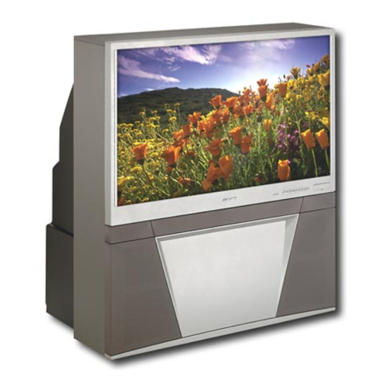
MITSUBISHI ELECTRIC
WS-48515
CAUTION:
Before servicing this chassis, it is important that the service person read the "SAFETY PRECAUTIONS" and
"PRODUCT SAFETY NOTICE" contained in this manual.
• Power Input
: AC 120V, 60Hz
• Power Usage
: 275W
• Frequency Range
: VHF 54 ~ 470MHz
• Antenna Input
: VHF/UHF 75Ω unbalanced
• CRT Size
: [7 inches]
: [9 inches] WS-65815/ WS-73615 only
• High Voltage
: 32.0kV (at 0A)
• Cabinet Weight and Dimensions (Refer to page 5)
• Speakers (8 Ohms 10W)
: 2-5" full range
[WS-48515]
: 2-6" full range
[WS-55515 / WS-65515]
: 2-6" coaxials
[WS-55615 / WS-65615 / WS-73615]
: 2-5"x7" coaxial [WS-55815 / WS-65815]
• Design specifications are subject to change without notice.
MITSUBISHI DIGITAL ELECTRONICS AMERICA, INC.
SPECIFICATIONS
300W [WS-65815/ WS-73615 only]
UHF 470 ~ 806MHz
1 NTSC /ATSC /QAM
1 NTSC for PIP
9351 Jeronimo Road, Irvine, CA 92618-1904
Copyright © 2004 Mitsubishi Digital Electronics America, Inc.
All Rights Reserved
Service
Manual
PROJECTION TELEVISION
V25 / V25+ / V25++ CHASSIS
V25+ MODELS
V25 MODELS
WS-48515
WS-55515
WS-65515
V25++ MODELS
WS-55815
WS-65815
• Input Level
: VIDEO IN JACK (RCA Type)
1.0Vp-p 75Ω unbalanced
: AUDIO IN JACK (RCA Type)
-4.7dBm 43kΩ unbalanced
: S-VIDEO IN JACK
(Y/C separate type)
Y:1.0 Vp-p C:0.286Vp-p(BURST)
75Ω unbalanced
: COMP / Y, Cr, Cb (RCA Type)
Y: 1.0 Vp-p Cr, Cb: 700mVp-p
• Output Level
: VIDEO OUT JACK (RCA Type)
1.0Vp-p 75Ω unbalanced
: AUDIO OUT JACK (RCA Type)
-4.7dBm 4.7kΩ unbalanced
• Digital
: IEEE-1394 I/O Jacks
Interface
: AC-3 Digtal Audio Output
: HDMI
: 4 Memory Card Reader Inputs
(V25++ Only)
: CableCARD
: System 5 IR
: USB Service Port
2004
WS-55615
WS-65615
WS-73615
Advertisement
Table of Contents

Related Manuals for Mitsubishi WS-48515


Summary of Contents for Mitsubishi WS-48515
-
Page 1: Schematic Diagrams Pcb Interconnect Diagram
2004 Service MITSUBISHI ELECTRIC Manual PROJECTION TELEVISION V25 / V25+ / V25++ CHASSIS V25+ MODELS V25 MODELS WS-55615 WS-48515 WS-48515 WS-65615 WS-55515 WS-73615 WS-65515 V25++ MODELS WS-55815 WS-65815 CAUTION: Before servicing this chassis, it is important that the service person read the "SAFETY PRECAUTIONS" and "PRODUCT SAFETY NOTICE"... -
Page 3: Table Of Contents
MODELS: WS-48515 / WS-55515 / WS-55615 / WS-55815 / WS-65515 / WS-65615 / WS-65815 / WS-73615 CONTENTS INTRODUCTION ..........................5 CABINET WEIGHT & DIMENSIONS ....................5 PRODUCT SAFETY NOTICE ......................5 DISASSEMBLY PROCEDURES ......................7 WS-48515 Front Cabinet Components ....................7 Rear Cabinet Components ..................... -
Page 4: Pcb-Terminal -2 [Pic Μp / Fif / E2P]
MODELS: WS-48515 / WS-55515 / WS-55615 / WS-55815 / WS-65515 / WS-65615 / WS-65815 / WS-73615 Convergence Adjustment Mode ..................... 34 Adjustment Items List ........................36 Adjustment Procedures ........................ 39 Test Point Locations ......................39 HV Regulation & Main / Sub Y Level ..................40 Main / Sub Color Level &... -
Page 5: Introduction
MODELS: WS-48515 / WS-55515 / WS-55615 / WS-55815 / WS-65515 / WS-65615 / WS-65815 / WS-73615 INTRODUCTION This service manual provides service instructions for the V25, V25+ and V25++ PTV chassis types. The specific models for each chassis type are listed below. Service personnel should read this manual thoroughly before servicing these chassis. -
Page 6: Pcb-Hdmi
MODELS: WS-48515 / WS-55515 / WS-55615 / WS-55815 / WS-65515 / WS-65615 / WS-65815 / WS-73615 SAFETY PRECAUTIONS NOTICE: Observe all cautions and safety related notes located inside the receiver cabinet and on the receiver chassis. WARNING: Operation of this receiver outside the cabinet or with the cover removed presents a shock hazard from the receiver's power supplies. -
Page 7: Disassembly Procedures
MODELS: WS-48515 / WS-55515 / WS-55615 / WS-55815 / WS-65515 / WS-65615 / WS-65815 / WS-73615 CABINET DISASSEMBLY (FRONT VIEW) WS-48515 *Refer to the Parts List for Part Numbers Front Cabinet Disassembly 1. Remove the Speaker Grille by pulling forward. -
Page 8: Rear Cabinet Components
MODELS: WS-48515 / WS-55515 / WS-55615 / WS-55815 / WS-65515 / WS-65615 / WS-65815 / WS-73615 CABINET DISASSEMBLY (REAR VIEW) WS-48515 *Refer to the Parts List for Part Numbers Rear Cabinet Disassembly 1. Remove the Back Board by removing 18 screws (a). -
Page 9: Ws-55515 / Ws-55615 / Ws-65515 / Ws-65615 Front Cabinet Components
MODELS: WS-48515 / WS-55515 / WS-55615 / WS-55815 / WS-65515 / WS-65615 / WS-65815 / WS-73615 CABINET DISASSEMBLY (FRONT VIEW) WS-55515 / WS-65515 / WS-55615 / WS-65615 *Refer to the Parts List for Part Numbers Front Cabinet Disassembly 1. Remove the Speaker Grille by pulling forward. -
Page 10: Rear Cabinet Components
MODELS: WS-48515 / WS-55515 / WS-55615 / WS-55815 / WS-65515 / WS-65615 / WS-65815 / WS-73615 CABINET DISASSEMBLY (REAR VIEW) WS-55515 / WS-65515 / WS-55615 / WS-65615 *Refer to the Parts List for Part Numbers Rear Cabinet Disassembly 1. Remove 9 screws (a) and 6 screws (b) holding the Back Board. -
Page 11: Front Cabinet Components
MODELS: WS-48515 / WS-55515 / WS-55615 / WS-55815 / WS-65515 / WS-65615 / WS-65815 / WS-73615 CABINET DISASSEMBLY (FRONT VIEW) WS-55815 *Refer to the Parts List for Part Numbers Front Cabinet Disassembly 1. Remove the Speaker Grille by pulling forward. -
Page 12: Rear Cabinet Components
MODELS: WS-48515 / WS-55515 / WS-55615 / WS-55815 / WS-65515 / WS-65615 / WS-65815 / WS-73615 CABINET DISASSEMBLY (REAR VIEW) WS-55815 *Refer to the Parts List for Part Numbers Rear Cabinet Disassembly 1. Remove 21 screws (a) holding the Back Board. -
Page 13: Front Cabinet Components
MODELS: WS-48515 / WS-55515 / WS-55615 / WS-55815 / WS-65515 / WS-65615 / WS-65815 / WS-73615 CABINET DISASSEMBLY (FRONT VIEW) WS-65815 *Refer to the Parts List for Part Numbers Front Cabinet Disassembly 1. Remove the Speaker Grille by pulling forward. -
Page 14: Rear Cabinet Components
MODELS: WS-48515 / WS-55515 / WS-55615 / WS-55815 / WS-65515 / WS-65615 / WS-65815 / WS-73615 CABINET DISASSEMBLY (REAR VIEW) WS-65815 *Refer to the Parts List for Part Numbers Rear Cabinet Disassembly 1. Remove 9 screws (a) and 9 screws (b) holding the Back Board. -
Page 15: Front Cabinet Components
MODELS: WS-48515 / WS-55515 / WS-55615 / WS-55815 / WS-65515 / WS-65615 / WS-65815 / WS-73615 CABINET DISASSEMBLY (FRONT VIEW) WS-73615 *Refer to the Parts List for Part Numbers Front Cabinet Disassembly 1. Remove the Speaker Grille by pulling forward. -
Page 16: Rear Cabinet Components
MODELS: WS-48515 / WS-55515 / WS-55615 / WS-55815 / WS-65515 / WS-65615 / WS-65815 / WS-73615 CABINET DISASSEMBLY (REAR VIEW) WS-73615 *Refer to the Parts List for Part Numbers Rear Cabinet Disassembly 1. Remove 9 screws (a), 6 screws(b) holding the Back Board. -
Page 17: Servicing The Lenticular Lens And Fresnel Screen
MODELS: WS-48515 / WS-55515 / WS-55615 / WS-55815 / WS-65515 / WS-65615 / WS-65815 / WS-73615 SERVICING THE LENTICULAR SCREEN AND FRESNEL LENS CAUTION: Wear gloves when handling the Lenticular Screen and Fresnel Lens. This prevents cuts and finger prints. Do not place Fresnel Lens in the sun. -
Page 18: Servicing The Lenticular Screen And Fresnel Lens
MODELS: WS-48515 / WS-55515 / WS-55615 / WS-55815 / WS-65515 / WS-65615 / WS-65815 / WS-73615 SERVICING THE LENTICULAR SCREEN AND FRESNEL LENS WS-55515 / WS-65515 CAUTION: Wear gloves when handling the Lenticular Screen and Fresnel Lens. This prevents cuts and finger prints. Do not place Fresnel Lens in the sun. - Page 19 MODELS: WS-48515 / WS-55515 / WS-55615 / WS-55815 / WS-65515 / WS-65615 / WS-65815 / WS-73615 SERVICING THE LENTICULAR SCREEN AND FRESNEL LENS CAUTION: Wear gloves when handling the Lenticular Screen and Fresnel Lens. This prevents cuts and finger prints. Do not place Fresnel Lens in the sun.
- Page 20 MODELS: WS-48515 / WS-55515 / WS-55615 / WS-55815 / WS-65515 / WS-65615 / WS-65815 / WS-73615 SERVICING THE LENTICULAR SCREEN AND FRESNEL LENS CAUTION: Wear gloves when handling the Lenticular Screen and Fresnel Lens. This prevents cuts and finger prints. Do not place Fresnel Lens in the sun.
-
Page 21: Installation Of The Lenticular Screen And Fresnel Lens
MODELS: WS-48515 / WS-55515 / WS-55615 / WS-55815 / WS-65515 / WS-65615 / WS-65815 / WS-73615 SERVICING THE LENTICULAR SCREEN AND FRESNEL LENS 2. Lenticular Screen and Fresnel Lens Installation. Note: Store the Lenticular Screen and Fresnel Lens in a cool dry place. High humidity may deform the Lenticular Screen and Fresnel Lens. -
Page 22: Tm Removal And Installation
MODELS: WS-48515 / WS-55515 / WS-55615 / WS-55815 / WS-65515 / WS-65615 / WS-65815 / WS-73615 SERVICING THE DIAMONDSHIELD™ 1. DiamondShield™ Removal Procedure The appropriate disassembly procedure given below. Note: Wear gloves when handling the DiamondShield™ to prevent finger prints. -
Page 23: Cabinet Separation Procedures Ws-65815
MODELS: WS-48515 / WS-55515 / WS-55615 / WS-55815 / WS-65515 / WS-65615 / WS-65815 / WS-73615 CABINET SEPARATION Mitsubishi 65 and 73 inch Projection TVs have been assembled in two pieces. These pieces may be separated for easier delivery and setup. The cabinet separation procedure requires two persons and varies between models. - Page 24 MODELS: WS-48515 / WS-55515 / WS-55615 / WS-55815 / WS-65515 / WS-65615 / WS-65815 / WS-73615 CABINET SEPARATION PROCEDURE (WS-65515 / WS-65615 / WS-737615) WS-65515 / WS-65615 Cabinet Separation Precedure 1. Pull the Speaker Grill from the cabinet. 2. Unplug the CC and ZF connectore 3.
-
Page 25: Servicing Pcbs
MODELS: WS-48515 / WS-55515 / WS-55615 / WS-55815 / WS-65515 / WS-65615 / WS-65815 / WS-73615 Main Chassis Removal Chassis Lock Chassis Chassis Removal Lock 1. Undo the cable wire ties to the Front Panel, Speakers, CRTs, etc. 2. Unplug the Card Reader USB and 1394 cables from the DM PCB. -
Page 26: Major Parts Locations
MODELS: WS-48515 / WS-55515 / WS-55615 / WS-55815 / WS-65515 / WS-65615 / WS-65815 / WS-73615 Main Components Location (Top View) DM Module Replacement 1. Unplug the Card Reader USB and 1394 cables from the DM module, and refer to the Chassis Removal Procedure to slide the chassis towards the rear of the set. -
Page 27: Crt Replacement
MODELS: WS-48515 / WS-55515 / WS-55615 / WS-55815 / WS-65515 / WS-65615 / WS-65815 / WS-73615 CRT REPLACEMENT 1. Removal of the CRT Caution! High voltage should be completely discharged prior to CRT removal. Since The CRTs receive high voltage from the HV Block, discharge by shorting the open end of the respective high voltage cable to chassis ground. -
Page 28: Crt Installation
MODELS: WS-48515 / WS-55515 / WS-55615 / WS-55815 / WS-65515 / WS-65615 / WS-65815 / WS-73615 2. Installation of the CRT Note: The replacement CRT is supplied as an assembly comprised of the CRT and the Inner Lens with the space between them filled with ethylene glycol. Care should be taken during handling and installation to prevent shock from disrupting the seal or alignment between the CRT and Inner Lens. - Page 29 MODELS: WS-48515 / WS-55515 / WS-55615 / WS-55815 / WS-65515 / WS-65615 / WS-65815 / WS-73615 2. Install the Deflection Yoke on the CRT neck. [Figure 5-7] 3. Install the Lens that was removed in step 6 of Removal Of The CRT. [ Figures 5-1 and 5-2 ] a) Position the Lens so that the Label faces the direction shown in Figure 5-8.
-
Page 30: Electrical Adjustments
MODELS: WS-48515 / WS-55515 / WS-55615 / WS-55815 / WS-65515 / WS-65615 /WS-65815 / WS-73615 ELECTRICAL ADJUSTMENTS Note: Perform only the adjustments required. Do not attempt an alignment if proper equipment is not available. Test Equipment • Oscilloscope (Unless otherwise specified, use 10:1 probes) •... -
Page 31: Initial Setup
MODELS: WS-48515 / WS-55515 / WS-55615 / WS-55815 / WS-65515 / WS-65615 /WS-65815 / WS-73615 Initial Setup A. Option Menu Setup (MENU-2-4-7-0) Follow the steps below for the initial set-up: OPTION MENU 1. Select the "MENU" display by pressing the "MENU" button once. -
Page 32: Led Indicator Diagnostics
MODELS: WS-48515 / WS-55515 / WS-55615 / WS-55815 / WS-65515 / WS-65615 /WS-65815 / WS-73615 C. A/V Memory Each of the external inputs has its’ own Audio/Video Memory. A change in an A/V setting at a specific input is stored in memory for that specific input. -
Page 33: Circuit Adjustment Mode
MODELS: WS-48515 / WS-55515 / WS-55615 / WS-55815 / WS-65515 / WS-65615 /WS-65815 / WS-73615 • To change to “Netcommand ” ... Hold the “Power” button and press “9-3-5” in sequence. • To change to “Standard” ... Hold the “Power” button and press “0-0-0” in sequence. -
Page 34: Service Mode Reset
MODELS: WS-48515 / WS-55515 / WS-55615 / WS-55815 / WS-65515 / WS-65615 /WS-65815 / WS-73615 D. Saving Adjustment Data Press “ENTER” to save adjustment data in memory. The character display turns red for approximately one second in this step. Note: If the circuit adjustment mode is terminated without pressing “ENTER”, changes in adjustment data are not saved. - Page 35 MODELS: WS-48515 / WS-55515 / WS-55615 / WS-55815 / WS-65515 / WS-65615 /WS-65815 / WS-73615 NOTE: When Item “1 HVOL” is selected the screen goes black except for the data display. This occurs since a black screen is required when making the HV Regulation adjustment.
-
Page 36: Adjustment Items List
MODELS: WS-48515 / WS-55515 / WS-55615 / WS-55815 / WS-65515 / WS-65615 /WS-65815 / WS-73615 E2PROM Replacement Data accessed in the Convergence Adjustment Mode is stored in IC8D01on the PCB-SIGNAL and on the PCB- E2P. Replacement PCB’s are supplied pre-aligned by model size so that only fine adjustments should be necessary after replacement. - Page 37 MODELS: WS-48515 / WS-55515 / WS-55615 / WS-55815 / WS-65515 / WS-65615 /WS-65815 / WS-73615 CONV GREEN Items (MENU-2-4-5-9-5) WS-55615 WS-65515 WS-48515 WS-55515 WS-65815 WS-73615 WS-55815 WS-65615 No. Abbrev. Description Name HSTA* Horizontal Position VSTA* Vertical Position SKEW Skew (Y axis rotation)
- Page 38 MODELS: WS-48515 / WS-55515 / WS-55615 / WS-55815 / WS-65515 / WS-65615 /WS-65815 / WS-73615 OSD Horizontal Centering (MENU-2-4-8-8) Abbrev. Description Data Name Display horiz. Centering (NTSC) DYNAMIC FOCUS (MENU-2-4-5-9-5) Item Abbrev. V25+ Description Number Name V25++ Dynamic Focus Horizontal...
-
Page 39: Adjustment Procedures
MODELS: WS-48515 / WS-55515 / WS-55615 / WS-55815 / WS-65515 / WS-65615 /WS-65815 / WS-73615 Adjustment Test Point Location Test Points DT pin 3 - HV Adjust DT pin 6 - Ground DT pin 7 - 12 Volts DT pin 8 - ACL... -
Page 40: Hv Regulation & Main / Sub Y Level
MODELS: WS-48515 / WS-55515 / WS-55615 / WS-55815 / WS-65515 / WS-65615 /WS-65815 / WS-73615 Purpose: To set the CRT Anode voltage. [HV Circuit] Symptom: Dark Picture 1. HV Regulation Measuring DC Voltmeter Note: This adjustment must be rechecked following Adjustment 4 CRT Cutoff. -
Page 41: Main / Sub Color Level & Crt Cutoff
MODELS: WS-48515 / WS-55515 / WS-55615 / WS-55815 / WS-65515 / WS-65615 /WS-65815 / WS-73615 To match the sub picture color to that of the main picture. [Video Circuit] Purpose: 3. Main/Sub Color Level Main and sub pictures colors differ. -
Page 42: White Balance (Ntsc) & White Balance (Hd)
MODELS: WS-48515 / WS-55515 / WS-55615 / WS-55815 / WS-65515 / WS-65615 /WS-65815 / WS-73615 Purpose: [CRT Circuit] To set the CRTs white level in the NTSC mode. Symptom: 5. White Balance (NTSC) Monochrome has a color tint. Measuring Note: Use the “FORMAT” button to activate the Expand mode (full screen). -
Page 43: Black Level & Sub Contrast
MODELS: WS-48515 / WS-55515 / WS-55615 / WS-55815 / WS-65515 / WS-65615 /WS-65815 / WS-73615 Purpose: [Video Circuit] To set the black level of the picture. Excess or insufficient brightness. Symptom: 7. Black Level Measuring ----- Instrument 1. Supply a Monoscope signal to a Video Input. -
Page 44: Dynamic Focus Presets & Lens Focus
MODELS: WS-48515 / WS-55515 / WS-55615 / WS-55815 / WS-65515 / WS-65615 /WS-65815 / WS-73615 [Focus Circuit] Purpose: To improve edge focus. 9. Dynamic Focus Preset Poor focus at the edges of the screen. Symptom: Measuring ----- 1. Supply a Monoscope signal to a Video Input Instrument 2. -
Page 45: Alignment Magnet / Electrostatic Focus & Charactrer Position
MODELS: WS-48515 / WS-55515 / WS-55615 / WS-55815 / WS-65515 / WS-65615 /WS-65815 / WS-73615 Purpose: [CRT Circuit] To set electrostatic focus to the optimum point. Symptom: Poor focus. 11. Electrostatic Focus & (Alignment Magnet) Measuring Note: This adjustment must be performed after the Sub Contrast adjustment. -
Page 46: Geometry Presets
MODELS: WS-48515 / WS-55515 / WS-55615 / WS-55815 / WS-65515 / WS-65615 /WS-65815 / WS-73615 [Conv/Defl] To preset data controlling raster geometry Purpose: 13. Geometry Preset Raster distortion. Symptom: ----- Measuring Procedure Instrument In the Circuit Adjustment and Coarse Convergence Modes pre-set the data to the... -
Page 47: Deflection Geometry Adjustments
MODELS: WS-48515 / WS-55515 / WS-55615 / WS-55815 / WS-65515 / WS-65615 /WS-65815 / WS-73615 Purpose: [Deflection Circuit] To set the height, width and linearity of the raster. Symptom: 14: Deflection Geometry Incorrect height, width and/or linearity. Height & Width Adjustment... -
Page 48: Convergence Geometry Adjustments
MODELS: WS-48515 / WS-55515 / WS-55615 / WS-55815 / WS-65515 / WS-65615 /WS-65815 / WS-73615 Purpose: [Convergence Circuit] To set the Convergence circuit geometry adjustments. Symptom: 15. Convergence Geometry Raster distortion at the top, bottom or sides of the picture. -
Page 49: Centering & Static Convergence
MODELS: WS-48515 / WS-55515 / WS-55615 / WS-55815 / WS-65515 / WS-65615 /WS-65815 / WS-73615 Purpose: [Convergence Circuit] To converge red, green and blue at the center of the screen Symptom: 16. Centering and Static Color edging over the entire picture. -
Page 50: Coarse Convergence Adjustments
MODELS: WS-48515 / WS-55515 / WS-55615 / WS-55815 / WS-65515 / WS-65615 /WS-65815 / WS-73615 [Convergence Circuit] To converge red and blue on green at the edges of the Purpose: screen. 17. Coarse Convergence Color edging at the top, bottom and sides of the screen. -
Page 51: Fine Convergence Adjustments
MODELS: WS-48515 / WS-55515 / WS-55615 / WS-55815 / WS-65515 / WS-65615 /WS-65815 / WS-73615 [Convergence Circuit] To converge red, green and blue at the edges of the screen Purpose: 18. Fine Convergence Color edging at the edges of the picture. -
Page 52: Chip Parts Replacement
MODELS: WS-48515 / WS-55515 / WS-55615 / WS-55815 / WS-65515 / WS-65615 / WS-65815 / WS-73615 CHIP PARTS REPLACEMENT Some resistors, shorting jumpers (0 Ohm resistors), Chip Parts Removal (Transistors) ceramic capacitors, transistors and diodes are chip parts. Melt the solder of one lead and lift the side of The following precautions should be taken when replacing that lead upward. -
Page 53: Replacement Parts
MODELS: WS-48515 / WS-55515 / WS-55615 / WS-55815 / WS-65515 / WS-65615 / WS-65815 / WS-73615 REPLACEMENT PARTS Parts Ordering To expedite delivery of replacement parts orders, specify the following: Model Number/Serial Number Part Number and description Quantity Note: Unless complete information is supplied, delay in processing of orders will result. -
Page 54: Quick Reference List
MODELS: WS-48515 / WS-55515 / WS-55615 / WS-55815 / WS-65515 / WS-65615 / WS-65815 / WS-73615 QUICK REFERENCE FOR COMMON REPLACEMENT PARTS CRT ASSEMBLIES MODEL ASSY-CRT-RED ASSY-CRT-GREEN ASSY-CRT-BLUE W S-48515 251C227010 251C227020 251C227030 W S-55515 251C227040 251C227050 251C227060 W S-55615... -
Page 55: Service Parts List
MODELS: WS-48515 / WS-55515 / WS-55615 / WS-55815 / WS-65515 / WS-65615 /WS-65815 / WS-73615 [#] Model Legend: (a) WS-48515, (b) WS-55515, (c) WS-55615, (d) WS-55815, (e) WS-65515, (f) WS-65615, (g) WS-65815, (h) WS-73615 Ref # Part # Part Name & Description... - Page 56 MODELS: WS-48515 / WS-55515 / WS-55615 / WS-55815 / WS-65515 / WS-65615 /WS-65815 / WS-73615 [#] Model Legend: (a) WS-48515, (b) WS-55515, (c) WS-55615, (d) WS-55815, (e) WS-65515, (f) WS-65615, (g) WS-65815, (h) WS-73615 Ref # Part # Part Name & Description...
- Page 57 MODELS: WS-48515 / WS-55515 / WS-55615 / WS-55815 / WS-65515 / WS-65615 /WS-65815 / WS-73615 [#] Model Legend: (a) WS-48515, (b) WS-55515, (c) WS-55615, (d) WS-55815, (e) WS-65515, (f) WS-65615, (g) WS-65815, (h) WS-73615 Ref # Part # Part Name & Description...
- Page 58 MODELS: WS-48515 / WS-55515 / WS-55615 / WS-55815 / WS-65515 / WS-65615 /WS-65815 / WS-73615 [#] Model Legend: (a) WS-48515, (b) WS-55515, (c) WS-55615, (d) WS-55815, (e) WS-65515, (f) WS-65615, (g) WS-65815, (h) WS-73615 Ref # Part # Part Name & Description...
- Page 59 MODELS: WS-48515 / WS-55515 / WS-55615 / WS-55815 / WS-65515 / WS-65615 /WS-65815 / WS-73615 [#] Model Legend: (a) WS-48515, (b) WS-55515, (c) WS-55615, (d) WS-55815, (e) WS-65515, (f) WS-65615, (g) WS-65815, (h) WS-73615 Ref # Part # Part Name & Description...
- Page 60 MODELS: WS-48515 / WS-55515 / WS-55615 / WS-55815 / WS-65515 / WS-65615 /WS-65815 / WS-73615 [#] Model Legend: (a) WS-48515, (b) WS-55515, (c) WS-55615, (d) WS-55815, (e) WS-65515, (f) WS-65615, (g) WS-65815, (h) WS-73615 Ref # Part # Part Name & Description...
- Page 61 MODELS: WS-48515 / WS-55515 / WS-55615 / WS-55815 / WS-65515 / WS-65615 /WS-65815 / WS-73615 [#] Model Legend: (a) WS-48515, (b) WS-55515, (c) WS-55615, (d) WS-55815, (e) WS-65515, (f) WS-65615, (g) WS-65815, (h) WS-73615 Ref # Part # Part Name & Description...
- Page 62 MODELS: WS-48515 / WS-55515 / WS-55615 / WS-55815 / WS-65515 / WS-65615 /WS-65815 / WS-73615 [#] Model Legend: (a) WS-48515, (b) WS-55515, (c) WS-55615, (d) WS-55815, (e) WS-65515, (f) WS-65615, (g) WS-65815, (h) WS-73615 Ref # Part # Part Name & Description...
- Page 63 MODELS: WS-48515 / WS-55515 / WS-55615 / WS-55815 / WS-65515 / WS-65615 /WS-65815 / WS-73615 [#] Model Legend: (a) WS-48515, (b) WS-55515, (c) WS-55615, (d) WS-55815, (e) WS-65515, (f) WS-65615, (g) WS-65815, (h) WS-73615 Ref # Part # Part Name & Description...
- Page 64 MODELS: WS-48515 / WS-55515 / WS-55615 / WS-55815 / WS-65515 / WS-65615 /WS-65815 / WS-73615 [#] Model Legend: (a) WS-48515, (b) WS-55515, (c) WS-55615, (d) WS-55815, (e) WS-65515, (f) WS-65615, (g) WS-65815, (h) WS-73615 Ref # Part # Part Name & Description...
- Page 65 MODELS: WS-48515 / WS-55515 / WS-55615 / WS-55815 / WS-65515 / WS-65615 /WS-65815 / WS-73615 [#] Model Legend: (a) WS-48515, (b) WS-55515, (c) WS-55615, (d) WS-55815, (e) WS-65515, (f) WS-65615, (g) WS-65815, (h) WS-73615 Ref # Part # Part Name & Description...
- Page 66 MODELS: WS-48515 / WS-55515 / WS-55615 / WS-55815 / WS-65515 / WS-65615 /WS-65815 / WS-73615 [#] Model Legend: (a) WS-48515, (b) WS-55515, (c) WS-55615, (d) WS-55815, (e) WS-65515, (f) WS-65615, (g) WS-65815, (h) WS-73615 Ref # Part # Part Name & Description...
- Page 67 MODELS: WS-48515 / WS-55515 / WS-55615 / WS-55815 / WS-65515 / WS-65615 /WS-65815 / WS-73615 [#] Model Legend: (a) WS-48515, (b) WS-55515, (c) WS-55615, (d) WS-55815, (e) WS-65515, (f) WS-65615, (g) WS-65815, (h) WS-73615 Ref # Part # Part Name & Description...
- Page 68 MODELS: WS-48515 / WS-55515 / WS-55615 / WS-55815 / WS-65515 / WS-65615 /WS-65815 / WS-73615 [#] Model Legend: (a) WS-48515, (b) WS-55515, (c) WS-55615, (d) WS-55815, (e) WS-65515, (f) WS-65615, (g) WS-65815, (h) WS-73615 Ref # Part # Part Name & Description...
-
Page 69: Screen Assembly Parts List
MODELS: WS-48515 / WS-55515 / WS-55615 / WS-55815 / WS-65515 / WS-65615 / WS-65815 / WS-73615 [#] Model Legend: (a) WS-48515, (b) WS-55515, (c) WS-55615, (d) WS-55815, (e) WS-65515, (f) WS-65615, (g) WS-65815, (h) WS-73615 Ref # Part # Part Name & Description... - Page 70 MODELS: WS-48515 / WS-55515 / WS-55615 / WS-55815 / WS-65515 / WS-65615 / WS-65815 / WS-73615 [#] Model Legend: (a) WS-48515, (b) WS-55515, (c) WS-55615, (d) WS-55815, (e) WS-65515, (f) WS-65615, (g) WS-65815, (h) WS-73615 Ref # Part # Part Name & Description...
- Page 71 MODELS: WS-48515 / WS-55515 / WS-55615 / WS-55815 / WS-65515 / WS-65615 / WS-65815 / WS-73615 [#] Model Legend: (a) WS-48515, (b) WS-55515, (c) WS-55615, (d) WS-55815, (e) WS-65515, (f) WS-65615, (g) WS-65815, (h) WS-73615 Ref # Part # Part Name & Description...
- Page 72 MODELS: WS-48515 / WS-55515 / WS-55615 / WS-55815 / WS-65515 / WS-65615 / WS-65815 / WS-73615 [#] Model Legend: (a) WS-48515, (b) WS-55515, (c) WS-55615, (d) WS-55815, (e) WS-65515, (f) WS-65615, (g) WS-65815, (h) WS-73615 Ref # Part # Part Name & Description...
-
Page 73: Circuitry Block Diagrams
MODELS: WS-48515 / WS-55515 / WS-55615 / WS-55815 / WS-65515 / WS-65615 / WS-65815 / WS-73615 POWER SUPPLY Page 73... - Page 74 MODELS: WS-48515 / WS-55515 / WS-55615 / WS-55815 / WS-65515 / WS-65615 / WS-65815 / WS-73615 VIDEO SIGNAL PATH Page 74...
- Page 75 MODELS: WS-48515 / WS-55515 / WS-55615 / WS-55815 / WS-65515 / WS-65615 / WS-65815 / WS-73615 A/V SWITCH Page 75...
- Page 76 MODELS: WS-48515 / WS-55515 / WS-55615 / WS-55815 / WS-65515 / WS-65615 / WS-65815 / WS-73615 SYNC PATH Page 76...
- Page 77 MODELS: WS-48515 / WS-55515 / WS-55615 / WS-55815 / WS-65515 / WS-65615 / WS-65815 / WS-73615 DEFLECTION / HV Page 77...
- Page 78 MODELS: WS-48515 / WS-55515 / WS-55615 / WS-55815 / WS-65515 / WS-65615 / WS-65815 / WS-73615 X-RAY PROTECT Page 78...
- Page 79 MODELS: WS-48515 / WS-55515 / WS-55615 / WS-55815 / WS-65515 / WS-65615 / WS-65815 / WS-73615 CONVERGENCE CIRCUIT Page 79...
- Page 80 MODELS: WS-48515 / WS-55515 / WS-55615 / WS-55815 / WS-65515 / WS-65615 / WS-65815 / WS-73615 SOUND CIRCUIT Page 80...
- Page 81 MODELS: WS-48515 / WS-55515 / WS-55615 / WS-55815 / WS-65515 / WS-65615 / WS-65815 / WS-73615 CONTROL CIRCUITRY Page 81...