Honeywell Dolphin 7800 User Manual
With windows embedded handheld 6.5
Hide thumbs
Also See for Dolphin 7800:
- Product data (8 pages) ,
- Quick start manual (17 pages) ,
- Quick start manual (19 pages)
Table of Contents
Advertisement
Quick Links
Advertisement
Table of Contents

Related Manuals for Honeywell Dolphin 7800


Summary of Contents for Honeywell Dolphin 7800
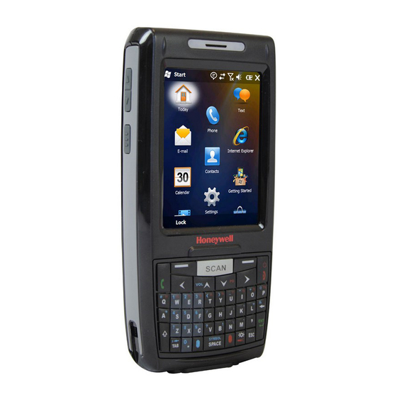
- Page 1 Dolphin™ 7800 ® with Windows Embedded Handheld 6.5 User’s Guide...
- Page 2 Disclaimer Honeywell International Inc. (“HII”) reserves the right to make changes in specifications and other information contained in this document without prior notice, and the reader should in all cases consult HII to determine whether any such changes have been made. The information in this publication does not represent a commitment on the part of HII.
-
Page 3: Table Of Contents
Table of Contents Chapter 1 - Dolphin 7800 Terminal Agency Information Laser Safety .........................1-1 Label Locations ......................1-1 Model Number, Serial Number and IMEI Labels............1-1 Laser Safety Label ......................1-1 Laser Safety Statement....................1-1 LED Safety ...........................1-2 LED Safety Statement....................1-2 UL and C-UL Statement.......................1-2 Approvals by Country......................1-2... - Page 4 Front Panel: 7800 ........................ 3-5 Front Panel Features for the 7800................. 3-6 Back Panel: 7800 ....................... 3-8 Back Panel Features for the 7800 ................. 3-9 Bottom Panel: 7800 ......................3-10 I/O Connector ........................3-10 Using the Touch Panel ...................... 3-11 Installing a Screen Protector..................
- Page 5 30-Key Numeric Keyboard ....................6-4 30-Key Numeric Keyboard Combinations..............6-4 30-Key Numeric (Calculator) Keyboard................6-6 30-Key Numeric (Calculator) Keyboard Combinations ..........6-6 46-Key QWERTY Keyboard ....................6-8 46-Key QWERTY Keyboard Combinations ..............6-8 46-Key AZERTY Keyboard....................6-11 46-Key AZERTY Keyboard Combinations..............6-11 46-Key QWERTZ Keyboard ....................
- Page 6 Installing Additional Software ....................8-8 Adding Programs Using ActiveSync or Windows Mobile Device Center....... 8-8 Connecting the Terminal to a Wireless Network............8-10 Adding Programs Using the Internet................8-10 Software Upgrades......................8-10 7800 COM Port Assignment Table..................8-11 Chapter 9 - Working with Wireless Wide Area Networking (WWAN) Overview..........................
- Page 7 Establishing Ethernet Communication................. 13-6 Establishing USB Communication ................13-7 Mounting the eBase......................13-7 Optional Hardware Mount.................... 13-8 Chapter 14 - Dolphin 7800 Mobile Base Device (Model 7800-MB) Overview..........................14-1 Mobile Base Components ....................14-2 Back Panel and Mounting Brackets................... 14-3 Mounting..........................
- Page 8 Connecting Power to the ChargeBase ................15-3 Charging the Main Battery....................15-4 To Power a Terminal and Charge its Main Battery............15-4 Mounting the ChargeBase....................15-4 Chapter 16 - Dolphin 7800 Net Base Device (Model 7800-NB) Overview..........................16-1 Parts and Functions......................16-2 Front Panel ........................16-2 Back Panel ........................
-
Page 9: Chapter 1 - Dolphin 7800 Terminal Agency Information
Dolphin 7800 Terminal Agency Information Dolphin 7800 mobile computers meet or exceed the requirements of all applicable standards organizations for safe operation. However, as with any electrical equipment, the best way to ensure safe operation is to operate them according to the agency guidelines that follow. Read these guidelines carefully before using your Dolphin terminal. -
Page 10: Led Safety
LED Safety LED Safety Statement LEDs have been tested and classified as “EXEMPT RISK GROUP” to the Standard: IEC 62471:2006. CAUTION! Do not view directly with optical instruments. UL and C-UL Statement UL and C-UL listed: UL60950-1 2nd Edition, and CSA C22.2 No. 60950-1-07 2nd Edition. Underwriters Laboratories Inc. -
Page 11: R&Tte Compliance Statement-802.11A/B/G/N, Bluetooth, And/Or Gsm
2006/95/EC Low Voltage Directive when supplied with the recommended power supply. Honeywell shall not be liable for use of our product with equipment (i.e., power supplies, personal computers, etc.) that is not CE marked and does not comply with the Low Voltage Directive. -
Page 12: Canadian Compliance
interference caused by unauthorized modifications of this equipment or the substitution or attachment of connecting cables and equipment other than those specified by our company. The correction is the responsibility of the user. Use only shielded data cables with this system. In accordance with FCC 15.21, changes or modifications not expressly approved by the party responsible for compliance could void the user’s authority to operate the equipment. -
Page 13: For European Community Users
1.5 cm from your body when the phone is switched on. For European Community Users Honeywell complies with Directive 2002/96/EC OF THE EUROPEAN PARLIAMENT AND OF THE COUNCIL of 27 January 2003 on waste electrical and electronic equipment (WEEE). -
Page 14: China Rohs
IEC specification. Hearing Aid Compatibility (HAC) The Dolphin 7800 has been tested for hearing aid compatibility. This device has an M3 and T3 rating. For additional HAC information, including the HAC rating for this product, please refer to www.honeywellaidc.com. -
Page 15: Microwaves
The ratings are not guarantees. Results will vary depending on the user's hearing device and hearing loss. If your hearing device happens to be vulnerable to interference, you may not be able to use this device successfully. Trying out this device with your hearing device is the best way to evaluate it for your personal needs. - Page 16 1 - 8...
-
Page 17: Chapter 2 - Getting Started
Guidelines for Battery Pack Use and Disposal on page 3-13. Dolphin 7800 model terminals are designed for use with standard battery pack model 7800-BTSC (Li-ion 3.7 V, 8.9 watt hour) and extended battery pack models 7800-BTXC and 7800-BTXCW (Li-ion 3.7 V, 14.8 watt hour) manufactured for Honeywell International Inc. - Page 18 3-3. Note: Honeywell recommends charging the Dolphin terminal for at least 24 hours prior to initial use to ensure the internal backup battery is fully charged. We recommend use of Honeywell peripherals, power cables, and power adapters. Use of any non-Honeywell peripherals, cables, or power adapters may cause damage not covered by the warranty.
- Page 19 Host Device Communication Cable (7800-USBH, 7800-DEX) Use only a UL Listed power supply, which has been qualified by Honeywell with an output rated at 5VDC and 3A with the device. Dolphin 7800 Plug Adapter Cable Cup Host Device Power Cable...
-
Page 20: Replacing The Main Battery Pack
Step 5. Set the Time Zone, Time, and Date On the Home screen, tap the line that displays the time and date. When the Clock & Alarms screen appears, tap the arrow to the right of the time zone to open the drop down menu. Select the appropriate time zone from the menu. -
Page 21: Home Screen
9. Press the Power key or the SCAN key to wake the terminal from Suspend Mode (see page 2-11). We recommend use of Honeywell Li-ion battery packs. Use of any non-Honeywell battery may result in damage not covered by the warranty. Home Screen After the Dolphin terminal initializes the first time, you see the Home screen. - Page 22 Call on hold Missed call Data call in progress A battery error has occurred. Replace the main battery pack with a Honeywell Li-ion battery pack. Battery is has a full charge Battery has a high charge Battery has a medium charge...
- Page 23 Icons in the Title Bar Indicator Meaning GPRS available GPRS connecting GPRS in use HSDPA available HSDPA connecting HSDPA in use EDGE available EDGE connecting EDGE in use UMTS available UMTS connecting UMTS in use Radio is off The radio is not connected to a network. The radio is connected.
-
Page 24: Horizontal Scroll
Horizontal Scroll The Horizontal Scroll, located at the top of most application windows, provides access to additional application screens. You can flick left or right on the scroll or tap each label on the scroll, until you get to the desired screen. Tapping a label to the left or right of the center item brings new labels into view. Note: Tap the Title bar to access the horizontal scroll if it is not visible on the screen. -
Page 25: File Explorer
File Explorer You can also use the File Explorer to find files and organize these files into folders. 1. Tap > File Explorer 2. Tap the Up button at the bottom of the screen to move up one level in the directory. 3. -
Page 26: File Provisioning On The 7800
\Honeywell The Honeywell partition or root file system partition is persistent over a Hard Reset, Soft Reset, and the removal of the battery pack or the removal of AC power. However, during a kernel upgrade the root file system is reformatted so all data in the folder is deleted and replaced by any files in the \IPSM\Honey- well\AutoInstall folder as part of the upgrade process. -
Page 27: Resetting The Terminal
There are three types of system resets: a soft reset, a hard reset, or a factory reset. The soft and hard resets preserve all data stored in the file system. Contact a Honeywell technical support representative for more information on how to perform a factory reset. - Page 28 2 - 12...
-
Page 29: Chapter 3 - Hardware Overview
Hardware Overview Standard Configurations for the 7800 WLAN & WPAN WLAN, WPAN & Camera • Microsoft Windows Embedded Handheld • Microsoft Windows Embedded Handheld 6.5 Classic 6.5 Classic • 800MHz TI OMAP Processor • 800MHz TI OMAP Processor • 256MB RAM X 512MB Flash •... - Page 30 WLAN, WPAN, WWAN with GPS & Camera WLAN, WPAN, & WWAN • Microsoft Windows Embedded Handheld • Microsoft Windows Embedded Handheld 6.5 Professional 6.5 Professional • 800MHz TI OMAP Processor • 800MHz TI OMAP Processor • 256MB RAM X 512MB Flash •...
-
Page 31: Peripherals For The 7800
13-1. Dolphin 7800 Net Base Device The Dolphin 7800 Net Base device enables up to four 7800 mobile computers to communicate with a host device over an Ethernet network. In addition, the Net Base provides a second RJ45 Ethernet port for connection to an additional device such as a printer, workstation, eBase, or another Net Base. -
Page 32: Accessories For The 7800
Dolphin 7800 Mobile Charger The Dolphin 7800 Mobile Charger is a charging cable that connects the terminal directly to a 12 Volt DC power source, such as a cigarette lighter port inside a vehicle, eliminating the need for a cradle. Intelli- gent battery technology on-board the terminal ensures proper charging. -
Page 33: Front Panel: 7800
Front Panel: 7800 Front Speaker Charge Indicator LED General Notification LED Touch Panel Display Volume Control Button Left Scan/Image Button Right Scan/Image Button SCAN Key Right Soft Key Left Soft Key Navigation Keys Power Key Send Call End Call Microphone Blue Modifier Key Red Modifier Key I/O Connector... -
Page 34: Front Panel Features For The 7800
Front Panel Features for the 7800 Blue Modifier Key Using the Modifier Keys on page 6-3. Charge Indicator LED The light emitting diode (LED) located above the top left corner of the LCD display illuminates when the Power Tools BattMon application is enabled and the device is on AC charge. For more information, consult the Dolphin Power Tools User’s Guide for Windows Embedded Handheld 6.5. - Page 35 SCAN Key The SCAN key is centrally located for easy access with the right or left hand. When pressed, the SCAN key activates the scanner/imager. The SCAN key also functions as a system wake- up control for the terminal. Touch Panel Display The color 3.7 inch 64k color liquid crystal display (LCD) touch panel is covered with an industrial, protective lens for greater durability.
-
Page 36: Back Panel: 7800
Back Panel: 7800 Image/Scan Engine Window* Stylus/Stylus Slot Hand Strap Hook Stylus Tether Rear Speaker Flashlight/Camera Flash Fastener for the Stylus Tether Color Camera Battery Lock Battery Release Button Battery Hand Strap Battery Well Memory Card Socket and SIM Card Socket (located under protective shield) Memory/SIM Shield Screws, Qty. -
Page 37: Back Panel Features For The 7800
Back Panel Features for the 7800 Battery Dolphin 7800 model terminals are designed for use with standard battery pack model 7800- BTSC (Li-ion 3.7 V, 8.9 watt hour) and extended battery pack models 7800-BTXC and 7800- BTXCW (Li-ion 3.7 V, 14.8 watt hour) manufactured for Honeywell International Inc. For... -
Page 38: Bottom Panel: 7800
When the protective SIM/memory card cover and battery pack are properly installed, the cards are sealed against moisture and particle intrusion, read/write data is stored securely, and the terminal’s environmental rating is preserved; see Installing a SIM Card and/or Memory Card on page 3-16. -
Page 39: Using The Touch Panel
Honeywell also mandates use of a proper stylus, which is one that has a stylus tip radius of no less than 0.8 mm. Use of the Honeywell stylus included with the terminal is recommended at all times. -
Page 40: Batteries
The standard battery pack requires 4 hours to charge completely before initial and the extended battery pack requires 6 hours to charge completely before initial use. Honeywell recommends charging the Dolphin terminal for at least 24 hours prior to initial use to ensure the internal backup battery is fully charged. - Page 41 Honeywell International Inc. or an authorized service center for inspection. • If you are not sure the battery or charger is working properly, send it to Honeywell International Inc. or an authorized service center for inspection, see...
-
Page 42: Internal Backup Battery
The internal backup battery must be fully charged before using the terminal for the first time. Honeywell recommends charging the Dolphin terminal for at least 24 hours prior to initial use to ensure the internal backup battery is fully charged. -
Page 43: Checking Battery Power
MedState=25% This sets the Low Battery point to 25%. When the battery hits the percentage charge specified here, the user is notified. LowState=10% This sets the Critical Battery point to 10%. When the battery hits the percentage charge specified here, the user is notified. Note: Warnings do not appear when the terminal is on external power. -
Page 44: Installing A Sim Card And/Or Memory Card
You can expand the terminal’s memory capacity by installing and industry-standard microSD or microS- DHC memory card. Contact a Honeywell sales representative for details on purchasing optional memory cards for your Dolphin terminal. Format all microSD/SDHC cards before initial use. - Page 45 If you are not installing a memory card (i.e., microSD or MicroSDHD card), proceed to step 11. 7. Unlock the memory card latch by sliding the latch toward the top of the terminal. 8. Lift the latch to expose the memory socket. 9.
- Page 46 13. Reinstall the shield and screws to protect the sockets. 14. Install and lock the battery. The terminal automatically starts the power up sequence. Note: The terminal does not power ON unless the battery lock is engaged. 3 - 18...
-
Page 47: Chapter 4 - Using The Scan Image Engine
Using the Scan Image Engine Overview The Dolphin terminal houses a compact image engine that instantly reads popular 1D and 2D bar codes and supports omni-directional aiming and decoding for greater flexibility in real-world settings. The image engine can also capture black and white digital images, such as signatures and pictures of dam- aged inventory. - Page 48 Focus N5603/N5600 N5603/N5600 N5603/N5600 High Density (HD) Standard Range (SR) Extended Range (ER) Symbology Distance (in/cm) Delta Distance (in/cm) Delta Distance (in/cm) Delta (in/cm) (in/cm) (in/cm) Near Near Near 3 mil C39/128 (5.1) (8.6) (3.6) 5 mil C39/128 (3.6) (12.2) (8.6) (6.9) (16.0)
-
Page 49: Supported Bar Code Symbologies
Supported Bar Code Symbologies Symbology Type Symbology Name 1D Symbologies Codabar ISBT 128 Codablock F Matrix 2 of 5 Code 3 of 9 MSI Plessey Code 11 Code 32 Pharmaceutical (PARAF) Code 93 Straight 2 of 5 IATA Code 128 Straight 2 of 5 Industrial EAN with Add-On Telepen... -
Page 50: Decoding
Decoding The terminal supports two types of image decoding for use in various bar code reading and imaging applications: full-area imaging and Advanced Linear Decoding (ALD). Full-Area Imaging Full-area imaging provides omni-directional reading of linear and non-linear 1D and 2D bar codes, OCR, signature capture, and picture taking. -
Page 51: Aiming Beam Options
Aiming Beam Options The aiming beams are smaller when the terminal is held closer to the code and larger when it is farther from the code. Symbologies with smaller bars or elements (mil size) should be read closer to the unit whereas symbologies with larger bars or elements (mil size) should be read farther from the unit. -
Page 52: Capturing Images
Capturing Images The image-capture process is an intuitive, split-second operation for experienced users. By following the basic guidelines, new users can easily develop their own technique and, with practice, quickly learn to adapt it to different application environments. Image Preview When the imaging process is initiated, the touch screen displays a preview of the object. -
Page 53: Uploading Images
Enabling the Aimer You can enable the aiming pattern for imaging in the Imaging Demo. For details about the aimer, see Aiming Beam Options on page 4-5. 1. Tap > Demos > Imaging Demo > Setup menu > Aimer. 2. The aiming pattern is now enabled for imaging. Uploading Images Image files can be uploaded to a host workstation using Microsoft ActiveSync or Windows Mobile Device Center and a Dolphin communication peripheral. - Page 54 4 - 8...
-
Page 55: Chapter 5 - Using The Color Camera
Using the Color Camera Overview Dolphin 7800 terminals equipped with a 3.0-Megapixels Resolution color camera with Automated Cam- era Control (ACC), and an Application Programming Interface (API) provide easy integration of color pic- ture and video capture into business applications. The camera lens and camera flash are located on the back panel of the terminal. -
Page 56: Taking A Picture Using The Windows Embedded Handheld 6.5 Camera Tool
Options Tap Options > Camera. The Camera Options menu appears. There are five tabs of configurable options accessible from the Camera Options menu. Profile Tab Display Tab The profile tab allows you to customize your camera settings, or chose from several predefined profiles designed to provide the best picture quality for common tasks. -
Page 57: Recording Video
6. Tap OK on the Tile Bar to return to the active viewfinder screen. Menu Tap Menu on the Tile Bar at the bottom of the touch screen to adjust the camera settings, switch to video mode, and access additional camera options. Item Descriptions Video... -
Page 58: Uploading Pictures And Videos
Uploading Pictures and Videos Picture and Video files can be uploaded to a host workstation using Microsoft ActiveSync or Windows Mobile Device Center and a Dolphin communication peripheral. For additional information see Connecting and Synchronizing the Terminal and Workstation on page 8-6. -
Page 59: Chapter 6 - Using The Keyboards
Using the Keyboards Available Keyboards Note: Contact a sales representative for information on additional keyboard options. 30-Key Numeric Keyboard 46-Key QWERTY Keyboard 30-Key Numeric (Calculator) Keyboard 46-Key AZERTY Keyboard 46-Key QWERTZ Keyboard All Keyboards Contain the Following: • Backlit for easy viewing in various lighting conditions. •... -
Page 60: Keyboard Combinations
Keyboard Combinations 30-Key Numeric Keyboard on page 6-4. 30-Key Numeric (Calculator) Keyboard on page 6-6. 46-Key QWERTY Keyboard on page 6-8. 46-Key AZERTY Keyboard on page 6-11. 46-Key QWERTZ Keyboard on page 6-14. Common Buttons Using the Function Keys on page 6-2. -
Page 61: Using The Modifier Keys
Using the Modifier Keys Name Function Blue & Red The blue and red keys are used in combination with other keys to type special characters and perform system functions. Each keyboard is Blue color-coded to indicate the character typed or function performed when specific keys are pressed immediately after the blue or red modifier key. -
Page 62: 30-Key Numeric Keyboard
Function & Moves the cursor up one page. Moves the cursor one character to the right. Moves the cursor one character to the left. Note: Additional functionality varies according to the application in use. 30-Key Numeric Keyboard Up Navigation Key, Volume Up, Page Up Down Navigation Key, Volume Down, Page Down SCAN Key Left Soft Key... - Page 63 Normal Blue + Normal Blue + Normal Red + Normal + Shift Right Soft Key Right Soft Key performs right function. SEND SEND Cold Boot Cold Boot SEND Left Navigation Left Up Navigation Volume Up Volume Up Volume Up Page Up Down Volume Down Volume Down...
-
Page 64: 30-Key Numeric (Calculator) Keyboard
Normal Blue + Normal Blue + Normal Red + Normal + Shift Period period asterisk asterisk period Blue Blue 30-Key Numeric (Calculator) Keyboard Up Navigation Key, Volume Up, Page Up Down Navigation Key, Volume Down, Page Down SCAN key Left Soft Key Right Soft Key Right Navigation key, Left Navigation key,... - Page 65 Normal Blue + Blue + Red + Normal Normal + Normal Shift Right Soft Right Soft Key SEND SEND Cold Boot Cold Boot SEND Left Left Backlight Left Left Volume Up Volume Up Volume Up Page Up Down Volume Volume Volume Page Down Down...
-
Page 66: 46-Key Qwerty Keyboard
Normal Blue + Blue + Red + Normal Normal + Normal Shift Period period asterisk asterisk period Blue Blue plus + 46-Key QWERTY Keyboard Up Navigation Key, Volume Up, Page Up Down Navigation Key, Volume Down, Page Down SCAN key Left Soft Key Right Soft Key Right Navigation key... - Page 67 Normal Shift + Normal Blue + Normal Red + Normal Left Soft Key Left Soft Key SCAN Scan Right Soft Key Right Soft Key Power/End Power/End Power/End Warm Boot Power/End Left Navigation Left Up Navigation Volume Up Page Up Down Down Down Volume Down...
- Page 68 Normal Shift + Normal Blue + Normal Red + Normal : (colon) ; (semi-colon) ‘ (single quote) “ (double quote) Backspace Backspace Backspace & (ampersand) Shift Shift ? (question mark) (exclamation point) \ (back slash) . (period) Comma , (comma) <...
-
Page 69: 46-Key Azerty Keyboard
46-Key AZERTY Keyboard Up Navigation Key, Volume Up, Page Up Down Navigation Key, Volume Down, Page Down SCAN key Left Soft Key Right Soft Key Right Navigation key Left Navigation key Power key, End Key Send key Backspace, Delete key Shift key Enter key Escape key... - Page 70 Normal Shift + Normal Blue + Normal Red + Normal Left Navigation Left Up Navigation Volume Up Page Up Down Down Down Volume Down Page Down Navigation Right Right Navigation # (number sign) + (plus) _ (underscore) - (minus) = (equal) "...
- Page 71 Normal Shift + Normal Blue + Normal Red + Normal Backspace Backspace Backspace Shift Shift % (percent) & (ampersand) ? (question mark) ! (exclamation mark) Comma , (comma) < , (comma) Enter Back Tab Back Tab Period . (period) > .
-
Page 72: 46-Key Qwertz Keyboard
46-Key QWERTZ Keyboard Up Navigation Key, Volume Up, Page Up Down Navigation Key, Volume Down, Page Down SCAN key Left Soft Key Right Soft Key Right Navigation key Left Navigation key Power key, End Key Send key Backspace, Delete key Shift key Enter key Escape key... - Page 73 Normal Shift + Normal Blue + Normal Red + Normal Down Down Down Volume Down Page Down Navigation Right Right Navigation # (number sign) + (plus) _ (underscore) - (minus) = (equal) “ (double quote) áU * (asterisk) / (forward slash) : (colon) ‘...
- Page 74 Normal Shift + Normal Blue + Normal Red + Normal % (percent) & (ampersand) ! (exclamation mark) ? (question mark) Comma , (comma) < , (comma) Enter Back Tab Back Tab Period . (period) > . (period) Blue Blue SYMBOL/ Space Space SYMBOL...
-
Page 75: Chapter 7 - System Settings
System Settings Overview Customized settings are available on the System Settings menu. Tap > Settings and the set- tings screen opens. Icon Description Bluetooth Configures the Bluetooth radio. See Working with the Bluetooth Radio on page Clock & Set the system clock, date, time and schedule alarms. See Clock &... -
Page 76: Clock & Alarms
Icon Description System Adjusts system settings. See System Menu on page 7-7. Microsoft My This icon is present on Dolphin models equipped with WWAN radio (GSM/UMTS/ GPRS/EDGE) capabilities. Microsoft My Phone synchronizes your phone’s contacts, Phone calendar, tasks, text messages, music, photos, videos, and other documents with your My Phone account at http://myphone.microsoft.com. -
Page 77: Personal Menu
Personal Menu To access the Personal Menu, tap > Settings > Personal . The screen opens displaying the Personal Menu. Icon Description Buttons Program the side buttons to perform specific tasks. See Buttons on page 7-3. Owner Enter your contact information (e.g., name, company, address, telephone number and E-mail address). - Page 78 Changing Button Assignments 1. After HotKeys is enabled, tap > Settings > Personal > Buttons Note: The buttons that appear on this window are the only buttons that can be programmed via the Buttons setting. You cannot add buttons to this window. 2.
- Page 79 Command Description <Right Softkey> Opens the menu or performs the action displayed on the right side of the Command bar. <Rotate Screen> Changes the screen orientation from portrait to landscape. <Scan1> Activates the scanner/imager. <Scan2> Activates the scanner/imager. <Scroll Down> Scrolls down in the open application.
- Page 80 3. Navigate to the Windows folder and open the Start Menu (My Device > Windows > Start Menu > Programs), tap and hold a blank area of the window, and tap Paste Shortcut on the pop-up menu. Note: If there is no blank space available in the window, tap on Menu > Edit > Paste Shortcut . 4.
-
Page 81: System Menu
System Menu The System menu enables you to verify and sometimes alter system parameters. To access the System menu, go to Start > Settings > System. Tap the appropriate icon to open that system setting. Icon See Page About About on page 7-8. -
Page 82: About
Icon See Page Five Volt Five Volt Control on page 7-12. Control Managed Managed Programs on page 7-13. Programs Memory Memory on page 7-14. Power Power on page 7-15. on page 7-15. Regional Regional Settings on page 7-16. Settings Remove Remove Programs on page 7-16. -
Page 83: Backlight
Backlight The Backlight system setting enables you to customize backlight functionality for the display. The back- light for the color display is user-defined. The Backlight system setting screen contains three tabs: Bat- tery Power, External Power, and Brightness. > Settings > System > Backlight. Battery Power Tab External Power Tab Brightness Tab... -
Page 84: Battery
Battery The Battery system settings menu contains two tabs: Battery Status and Log Config. The Battery Sta- tus tab provides the status of the main battery pack (e.g., Battery Time to Full or Battery Time to Empty, Voltage, Current, Temperature, Chemistry, and Serial Number). The Log Config Tab allows you to con- figure the BatteryLogFile. -
Page 85: Encryption
Encryption Encryption gives you the option of encrypting files placed on storage cards so that those files cannot be read by any other device. Error Reporting Error Reporting gives you the option of enabling or disabling the error reporting function of Windows Embedded Handheld 6.5. -
Page 86: Five Volt Control
Five Volt Control Five Volt Control gives you the option to manually enable 5V output to supply power to an external device. By default, 5-Volt Output automatically turns on when AC power is applied to the terminal. If you want to use a USB memory stick without AC power, then you must manually turn on the 5-Volt Output. Do not leave 5-Volt output enabled when you are not using it to supply power to an external device. -
Page 87: Managed Programs
Event Track displays an event log summary of detected free fall events exceeding 2 ft. over 250 ms. The summary includes the time, date, and duration of the most recent 50 events. Several options are provided for audible notification of free fall events. -
Page 88: Memory
Autoinstall programs, for example, are stored in \\IPSM\Honeywell\Autoin- stall so that they are always installed after an operating system upgrade or factory reset. Contact a Honeywell technical support representative for more information on how to perform a factory reset. For contact information, see... -
Page 89: Ril
Storage Card You can install one memory card in Dolphin terminals (see Installing a SIM Card and/ or Memory Card on page 3-16). If a storage card is installed in the terminal, you can select it in the drop-down list and see capacity and usage statistics for the card. The RIL Information screen displays useful statistics for the GSM WAN Voice module (PH8). -
Page 90: Regional Settings
If a program is manually removed using the Remove Programs application, the program does not re-install on a hard or soft reset. Note: A program (file) does not automatically install if it is added to the \\IPSM\Honeywell\Autoinstall folder and a hard or soft reset is performed. For information on program installation, see... - Page 91 2. Tap Remove. The following message appears: 3. Tap Yes. Wait while the program is removed. 4. Verify that the program no longer appears in the list. 7 - 17...
-
Page 92: Screen
Screen The Screen system setting contains three screens: General, Clear Type, and Text Size. General Screen Orientation The General screen enables you to set the dynamic screen rotation. Three choices of screen orientation are supported: Portrait, Landscape (right-handed), and Landscape (left- handed). -
Page 93: Task Manager
Text Size Screen The Text Size screen enables you to perform font scaling within certain views of the: • Home screen, • Contacts, • Calendar, • Messaging, and • Tasks. Font scaling means that you can increase or decrease the point size of the font on application windows. - Page 94 Using the Task Manager Applications To view the status of the programs running on your mobile computer, tap the Menu button at the bottom of the screen, then tap View > Applications. From the application list, you can: • Tap and hold on an application, then tap Switch To on the pop-up menu.
-
Page 95: Chapter 8 - Communication
Communication Connections Menu The Connections system setting provides access to the terminal’s various wireless communication options. Icon Tapping this icon… Beam Enable the terminal to receive incoming beams from devices using Bluetooth wireless technology. See Working with the Bluetooth Radio on page 10-1. -
Page 96: Connections Manager
Connections Manager Microsoft’s Connections Manager sets up multiple network connections to Internet Service Providers (ISPs) via external modem. Do NOT enter connection parameters in the Connections Manager if: • you are using one of the on-board wireless radios to connect to a network. The Dolphin terminal uses the settings from each radio’s configuration utility to connect. -
Page 97: Advanced
• Proxy server connection Note: If you are connected to your ISP or private network during synchronization, the terminal should download the proper proxy settings during synchronization with the workstation. If these settings are not on your workstation or need to be changed, ask your ISP or network administrator for the proxy sever name, server type, port, type of Socks protocol used, and your user name and password. -
Page 98: Dolphin Wireless Manager
Dolphin Wireless Manager The Dolphin Wireless Manager provides a centralized interface that enables and disables all the on- board radios. Each radio has its own configuration program. The Dolphin Wireless Manager also pro- vides shortcuts to the configuration utilities for each radio. on the Home screen to access the Dolphin Wireless Manager. -
Page 99: Accessing Radio Configuration Utilities
Each radio has its own configuration utility that you can access by tapping Menu on the tile bar. Radio Type Menu Option Tap WLAN Settings and the Honeywell WLAN Security Supplicant opens. 802.11a/b/g/n The Honeywell WLAN Security Supplicant User’s Guide is available for download from the Dolphin 7800 product page at www.honeywellaidc.com. -
Page 100: Network Cards
When communicating via ActiveSync or WMDC, your terminal is designed to be connected to the host workstation with a communication peripheral sold/manufactured by Honeywell, such as the charge/ communication cable. Use of any peripheral not sold/manufactured by Honeywell may cause damage not covered by the warranty. - Page 101 (see page 3-10) on the bottom panel of the terminal. The maximum data transfer rate is 480 Mbps. A USB cable and a Honeywell hardware peripheral (e.g., HomeBase) allow the terminal to com- municate with a workstation or to networked through a USB hub. The Dolphin terminal defaults to USB communication out of the box.
-
Page 102: Installing Additional Software
Installing Additional Software Dolphin terminals ship with the operating system, radio drivers, and custom Honeywell software already installed. These are the default programs that install when your terminal first boots up. You can install additional software programs to the terminal provided that the following parameters are met: •... - Page 103 • If you want the program to be part of the Autoinstall that occurs after a factory reset or software upgrade, paste the program file(s) in both the \IPSM\Honeywell\Autoinstall folder and the \Honeywell\Autoinstall. Note: Contact a Honeywell technical support representative for information on how to perform a factory reset. Technical Assistance on page 18-1 or go to www.honeywellaidc.com.
-
Page 104: Connecting The Terminal To A Wireless Network
WLAN Radio The WLAN radio is configured in the Honeywell WLAN Security Supplicant, which you access by tapping the program icon in the task tray near the bottom of the touch screen. For complete configuration instruc- tions, download the Honeywell Secure Wireless Client (SWC) User’s Guide from... -
Page 105: 7800 Com Port Assignment Table
To prevent data loss, back up all user data to an SD card or external memory device before performing an upgrade. Note: An active Microsoft ActiveSync or Windows Mobile Device Center connection between a host workstation and the Dolphin terminal may be required for some types of software upgrades. For additional information, see Connecting and Synchronizing the Terminal and Workstation on page 8-6. - Page 106 8 - 12...
-
Page 107: Chapter 9 - Working With Wireless Wide Area Networking (Wwan)
Working with Wireless Wide Area Networking (WWAN) Overview The 7800 has two options for WWAN connectivity, a voice + data GSM/HSPA+/UMTS/GPRS/EDGE or a data only Gobi radio, which supports GSM/HSPA+/UMTS/GPRS/EDGE and CDMA/1xRTT/EVDO Rev A. Short for Global System for Mobile communications, GSM is an open, non-proprietary wireless WAN system that is constantly evolving and growing. - Page 108 Signal Strength On terminals equipped with a WWAN (voice + data) radio, the signal strength of the WWAN connection is indicated by the number of bars that appear in the signal strength icon in the Title bar at the top of the window.
-
Page 109: Enabling The Wwan Radio
Enabling the WWAN Radio By default, the WWAN radio is not enabled after a factory reset. Verify the status of the radio in the Dol- phin Wireless Manager. on the Home screen to access the Dolphin Wireless Manager. If the WWAN radio is OFF, tap the rectangle to enable or turn ON the radio. Voice Communication, Using the Dolphin as a Phone If your Dolphin model is equipped for voice + data WWAN connectivity, you can use the terminal as a phone over the GSM radio. -
Page 110: Accessing The Dialer Window
Volume Control Use the Dolphin keyboard to adjust the volume. & To raise the volume, press the Blue modifier key + up arrow. Blue To lower the volume, press the Blue modifier key + down arrow. & Press the up or down arrow on the Volume Control button on the left side of the Blue device to adjust the volume of the active speaker, see Volume Control Button... -
Page 111: Sending Calls
Sending Calls After the number is dialed, tap Talk or press the Send key Note: The icon indicates that the phone is in use. Ending Calls While the phone call is live, tap End or End Key Accessing Voice Mail >... - Page 112 Security The Security screen provides access to establish or change your security PIN. Check the box next to, “Require a PIN when the phone is used” to enable the PIN security feature. Services For each service, the phone reads settings from the network stored on the SIM card and then displays the available options from the carrier on the screen.
-
Page 113: Data Communication (Gsm/Hspa+ Global Radio Dolphin Models)
Network You can find, select, and set your preferred network order from the Network screen. Data Communication (GSM/HSPA+ Global Radio Dolphin Models) You set up data communication via the Connections Manager. The carrier on the SIM card is the ISP. System Requirements •... - Page 114 3. Enter a name for the connection. Select Cellular Line (GPRS) as the modem. Tap Next. 4. Enter the Access point name. Tap Next. 5. Enter the user name and password from the account. Tap Finish. 9 - 8...
- Page 115 6. The connection you just created should appear in the list on the modem tab. 7. Tap and hold on the connection. Select Connect on the popup menu. 8. The network icon in the Title bar indicates the GSM radio is attempting to connect Note: When the device is on a 2G (EDGE/GPRS) network, a data connection failure occurs if the phone is in use for a voice call while attempting a data connection.
-
Page 116: Manual Network Selection
Manual Network Selection You can select Automatic or Manual network selection. The Phone defaults to Automatic network selec- tion. 1. When an active SIM card is inserted in the terminal, tap > Settings > Personal > Phone > Menu > Options. 2. -
Page 117: Data Communication (Gsm/Cdma Dolphin Models)
Data Communication (GSM/CDMA Dolphin Models) Gobi Manager The Gobi Manager enables you to see real time status of the radio, setup your Network selection, view you’re profile and scan for networks. The Gobi Manager contains four tabs: Status, Setup, Profile, and About. -
Page 118: Establishing Data Communication
Profile Tab The Profile tab allows you to see Radio capability information and network statistics including: • Radio Hardware and Software versions • Radio and SIM identification numbers • Serving network connection type and state • Available radio interfaces for the current serving network About Tab Displays copyright and version information for the Gobi Connection Manager. -
Page 119: Chapter 10 - Working With The Bluetooth Radio
Working with the Bluetooth Radio Enabling the Bluetooth Radio You enable the Bluetooth radio in the Dolphin Wireless Manager (see page 8-4). 1. Tap on the Home screen to access the Dolphin Wireless Manager. 2. Tap anywhere inside the Bluetooth rectangle and Bluetooth begins activating. 3. -
Page 120: Pairing And Trusted Devices
Pairing and Trusted Devices The terminal does support pairing. Pairing happens during general connection setup. Paired devices are "trusted" devices. This means that there is unrestricted access to all services (including services that require authorization and authentication). A connection can exclude pairing. A device that is connected to the terminal but not paired with it is con- sidered an untrusted device. - Page 121 4. Select a device from the list and tap Next. The types of devices in the vicinity of the radio appear in the list of discovered devices. 5. You are prompted to enter a passcode. • If the device has a specific passcode, enter it in the Passcode field and tap Next. When attempting to connect to a printer or headset with Bluetooth capabilities, the passcode may default to either 1111 or 0000.
- Page 122 8. When the connection is complete, a list of matching and supported services on the device appears. Only the services that are mutually supported on both devices appear in the Partnership Settings window. 9. Select the services you want to use and tap Save. The services on the new devices have to be selected or the pairing won’t include those services, even though the devices are paired.
-
Page 123: Transferring Files
Transferring Files Before attempting to transfer files, make sure the receiving Bluetooth device is in range, set to be discov- erable by other devices, and set to receive incoming beams. 1. Tap > File Explorer. 2. Navigate to the file you want to transfer. 3. -
Page 124: Making The Terminal Discoverable
7. When the file is being transferred, the selected device reads “Sending”. Making the Terminal Discoverable By default, the Dolphin terminal is not discoverable, which means that the terminal will not be found by other Bluetooth devices. 1. To make the terminal discoverable, tap >... -
Page 125: Selecting Com Ports
Selecting COM Ports You can select COM ports 0-9. For more information, see 7800 COM Port Assignment Table on page 10 - 7... - Page 126 10 - 8...
-
Page 127: Chapter 11 - Working With Gps
Working with GPS Overview The Dolphin 7800 terminal contains an integrated GPS module that allows location tracking of workers and vehicles, providing better utilization of field assets. Optional mapping and navigation software pro- vides turn-by-turn driving directions and location information. -
Page 128: Gps Intermediate Driver
GPS Intermediate Driver When the first user of GPD1 opens the port, the GPS Intermediate Driver opens the COM7 port. The GPS Intermediate Driver allows multiple applications to open GPD1, and the GPS data is broadcast to all open ports. When the GPSID driver is in use, the COM7 port is allocated to GPSID as READ|WRITE (COM7 is still available for access mode of 0). -
Page 129: Chapter 12 - Dolphin 7800 Homebase Device (Model 7800-Hb)
BTSCW (Li-ion 3.7 V, 8.9 watt hour) and extended battery pack 7800-BTXC or 7800-BTXCW (Li-ion 3.7 V, 14.8 watt hour) manufactured for Honeywell International Inc., and with Dolphin 7800 model terminals. Warning! The HomeBase is not designed for use in hazardous locations. -
Page 130: Parts And Functions
This means that one base can charge two bat- tery packs: the one installed in the terminal and a spare. We recommend use of Honeywell Li-ion battery packs. Use of any non-Honeywell battery may result in damage not covered by the warranty. -
Page 131: Back Panel
Red, Flashing The internal temperature of the auxiliary battery is too hot or there is a battery error. Charge the auxiliary battery in a cooler environment or replace the battery with a new Honeywell battery. For information about charging a battery in the auxiliary battery well, see page 12-5. -
Page 132: Bottom Panel
AC power source to 12 Volts DC. Use only a UL listed power supply, which has been qualified by Honeywell with output rated at 12VDC and 3 amps with the device. The operating temperature range is -10° to 50°C (14° to 122°F) Honeywell recommends that you leave the base connected to its power source at all times, so that it is always ready to use. -
Page 133: Charging The Main Battery
Ensure all components are dry prior to mating terminals/batteries with peripheral devices. Mating wet components may cause damage not covered by the warranty. We recommend use of Honeywell Li-Ion battery packs. Use of any non-Honeywell battery may result in damage not covered by the warranty. -
Page 134: Communication
• The Dolphin terminal activates; if the power is off, the terminal automatically powers on. If the terminal does not power on, verify that the Honeywell power supply is properly connected to the cradle and plugged into a functioning outlet. -
Page 135: Mounting The Homebase
Mounting the HomeBase Set the base on a dry, stable surface, such as a desktop or workbench near an electrical outlet. Be sure to provide enough workspace with good lighting for the user to view and operate the Dolphin terminal while it is in the base. - Page 136 12 - 8...
-
Page 137: Chapter 13 - Dolphin 7800 Ebase Device (Model 7800-Ehb)
Dolphin 7800 eBase Device (Model 7800-EHB) Overview The Ethernet Base (eBase) enables a single Dolphin 7800 computer to communicate with a host device over an Ethernet network. The 7800-EHB charger is designed for use with standard battery pack model 7800-BTSC or 7800- BTSCW (Li-ion 3.7 V, 8.9 watt hour) and extended battery pack model 7800-BTXC or 7800-BTXCW (Li-... -
Page 138: Parts And Functions
Capacity The base holds one terminal and features an auxiliary battery well behind the terminal well that can charge a battery pack independently of the terminal well. This means that one base can charge two bat- tery packs: the one installed in the terminal and a spare. Parts and Functions Front Panel Terminal Well... -
Page 139: Back Panel
Red Flashing The internal temperature of the auxiliary battery is too hot or there is a battery error. Charge the auxiliary battery in a cooler environment or replace the battery with a Honeywell battery. COMM LED The COMM LED indicates the status of data transfer between the Dolphin terminal and the eBase. -
Page 140: Bottom Panel
12 Volts DC. Use only a UL listed power supply, which has been qualified by Honeywell with output rated at 12VDC and 3 amps with the device. The operating temperature range is -10° to 50°C (14° to 122°F). Honeywell recommends that you leave the eBase connected to its power source at all times, so that it is always ready to use. -
Page 141: Connecting Power To The Ebase
Ensure all components are dry prior to mating terminals/batteries with peripheral devices. Mating wet components may cause damage not covered by the warranty. We recommend use of Honeywell Li-Ion battery packs. Use of any non-Honeywell battery may result in damage not covered by the warranty. -
Page 142: Communication
Charge the auxiliary battery in a cooler environment or replace the battery with a new Honeywell Li-ion battery. Communication Software Requirements Before you connect the Dolphin terminal to the eBase, make sure you have the most current software installed. -
Page 143: Establishing Usb Communication
Displaying the eBase and Terminal IP Address Once the Dolphin terminal has been successfully connected to the eBase, the terminal uses the eBase IP address. This IP address can be used by any application on the Dolphin terminal. > Power Tools > Network Utilities > IPConfig . 1. -
Page 144: Optional Hardware Mount
Optional Hardware Mount On the bottom of the HomeBase there are four mounting holes with a maximum depth of 7 mm that can be used to secure the base to a horizontal surface such as a desktop or workbench using M3 self tap- ping screws. -
Page 145: Chapter 14 - Dolphin 7800 Mobile Base Device (Model 7800-Mb)
The base features a mounting bracket and a cigarette lighter adapter to adapt it to your environment. The 7800-MB charger is designed for use with Dolphin 7800 model terminals using standard battery pack model 7800-BTSC or 7800-BTCW (Li-ion 3.7 V, 8.9 watt hour) or extended battery pack model 7800-BTXC or 7800-BTXCW (Li-ion 3.7 V, 14.8 watt hour) manufactured for Honeywell International Inc. -
Page 146: Mobile Base Components
Mobile Base Components Mounting Back Plate Terminal Well Power Adapter Terminal Locking Lever Adapter Power LED (not in view) Mounting Back Plate Used to mount the base to a fixed location. Terminal Locking Lever The mobile base has a locking lever on the front. When the lever is in the down position the terminal in locked in the base. -
Page 147: Back Panel And Mounting Brackets
Back Panel and Mounting Brackets Ball Joint Pivot Bracket Base Mounting Bracket Turnscrew Ball Joint Ball Joints There are two ball joints: one that is attached to back of the base and one on the mounting bracket. Both ball joints are inserted into the bracket and secured to mount the base. Pivot Bracket The bracket contains the turnscrew and two slots. -
Page 148: Mounting
Safety Precautions Honeywell is not responsible for any damages caused to you, your vehicle, or other individuals due to the installation of the Dolphin Mobile mount. Follow these safety precautions when mounting the mobile base:... -
Page 149: Charging The Main Battery
For more information about Honeywell battery packs and how to check battery power levels in your ter- minal, refer to... - Page 150 14 - 6...
-
Page 151: Chapter 15 - Dolphin 7800 Chargebase Device (Model 7800-Cb)
4 hours for the standard battery or 6 hours for the extended battery. The 7800-CB charger is designed for use with Dolphin 7800 model terminals using one of the following battery pack models: standard battery pack model 7800-BTSC (Li-ion 3.7 V, 8.9 watt hour), extended battery pack model 7800-BTXC, or extended pack model 7800BTXCW (Li-ion 3.7 V, 14.8 watt hour) -
Page 152: Parts And Functions
Parts and Functions Front Panel Terminal Wells (Qty. 4) Power/Dock LED (Qty. 4) Charge LED (Qty. 4) Terminal Wells The base contains four terminal wells. Each well has its own dedicated Power/Docking LED and Charging LED indicator. Power/Dock LEDs The Power/Dock LED indicates if the ChargeBase has power and if the terminal is properly seated in the terminal well. -
Page 153: Back Panel
12 volts DC. Use only a UL Listed power supply, which has been qualified by Honeywell with output rated at 12VDC and 8.5 amps with the device. The operating temperature range is -10° to 45°C (14° to 113°F). -
Page 154: Charging The Main Battery
Ensure all components are dry prior to mating terminals/batteries with peripheral devices. Mating wet components may cause damage not covered by the warranty. We recommend use of Honeywell Li-Ion battery packs. Use of any non-Honeywell battery may result in damage not covered by the warranty. -
Page 155: Desk Mounting
Desk Mounting The DIN Rail (7.5 X 35 mm) slot on the bottom panel enables secure mounting on a horizontal surface. Hardware Required • 3/16 in. dia x 5/8 in. long pan head screw • 1/2 in. OD x 7/32 in. ID x 3/64 in. thick •... - Page 156 Tools Required • Drill • 7/8 in. Drill Bit (for hollow wall installations) or 1/4 in. Drill Bit (for wood stud installation) • Phillips Screw Driver Hollow Wall Installation 1. Drill four pilot holes in the wall using a 7/8 in. drill bit. 13.78 in.
- Page 157 To secure the base using the optional DIN Rail: Hardware Required • DIN Rail, Qty. 1 • 3/16 in. dia x 5/8 in. long pan head screw, Qty. 2 • 1/2 in. OD x 7/32 in. ID x 3/64 in. thick washer, Qty. 2 •...
- Page 158 15 - 8...
-
Page 159: Chapter 16 - Dolphin 7800 Net Base Device (Model 7800-Nb)
Dolphin 7800 Net Base Device (Model 7800-NB) Overview The Net Base enables up to four Dolphin 7800 mobile computers to communicate with a host device over an Ethernet network. In addition, the Net Base provides a second RJ45 Ethernet port for connec- tion to an additional device such as a printer, workstation, eBase, or another Net Base. -
Page 160: Parts And Functions
Parts and Functions Front Panel Terminal Wells (Qty. 4) Power/Dock LED (Qty. 4) COMM LED (Qty. 4) Terminal Wells The Net Base contains four terminal wells. Each well has its own dedicated Power/Dock LED and COMM LED indicator. Place the Dolphin terminal in any one of the four wells to communicate with a host device, power the terminal, and charge the installed battery pack. -
Page 161: Back Panel
Back Panel Green LED (Qty. 1 Per Port) Yellow LED (Qty. 1 Per Port) Port 1: 10/100Mbps RJ45 Ethernet Port DC Power Jack Port 2: 100Mbps Only RJ45 Ethernet Port DC Power Jack This connector receives input from the power adapter. Plug the power connector cable from the power adapter into this connector, see Power on page... -
Page 162: Bottom Panel
12VDC, 8.5A with the device, which has been qualified by Honeywell. The oper- ating temperature range is -10° to 45°C (14° to 113°F). Honeywell recommends that you leave the Net Base connected to its power source at all times, so that it is always ready to use. -
Page 163: Charging The Main Battery
Ensure all components are dry prior to mating terminals/batteries with peripheral devices. Mating wet components may cause damage not covered by the warranty. We recommend use of Honeywell Li-Ion battery packs. Use of any non-Honeywell battery may result in damage not covered by the warranty. -
Page 164: Connecting The Dolphin Terminal To The Net Base
Connecting the Dolphin Terminal to the Net Base By default, the Dolphin terminal is configured to obtain IP addresses automatically using a DHCP server. This means that in most cases, you would simply plug-and-play the unit. 1. Verify the base has power. If the Power/Dock LEDs are not illuminated, see Connecting Power to the Net Base on page... - Page 165 Bottom Panel Rubber Feet, Qty. 8 DIN Rail Slot Optional Mounting Holes for M3 self tapping screws, Qty. 4. Maximum thread depth of 7 mm. Desk Mounting The DIN Rail (7.5 X 35 mm) slot on the bottom panel enables secure mounting on a horizontal surface. Hardware Required •...
- Page 166 3. Then, using the appropriate nuts and bolts, secure the DIN Rail to a stable, flat horizontal surface. DIN Rail (7.5 x 35 mm) Wall Mounting The optional wall mount bracket enables secure mounting of the base on a vertical surface. The wall mount bracket can be used in conjunction with the DIN rail but does not require the DIN Rail for use.
- Page 167 2. Slide the bolt through the wall bracket, and thread the toggle nut onto Toggle Nut the bolt. Bolt 3. Press the ends of the toggle nut together, and insert the bolt/nut into the pilot hole until the nut clears inside wall surface. The toggle nut should spring open preventing the screw from being removed.
- Page 168 3. Slide the washer onto the screw and tighten the nut to secure the assembly. Wall Bracket, Qty. 1 Screw, Qty. 2 Washer, Qty. 1 DIN Rail, Qty. 1 Nut, Qty. 1 Washer, Qty. 1 Nut, Qty. 1 4. Remove the rubber feet on the bottom of the ChargeBase. 5.
-
Page 169: Chapter 17 - Dolphin 7800 Quadcharger Device (Model 7800-Qc)
Battery Pack Use and Disposal on page 3-13. Capacity The charger holds 4 Honeywell standard or extended batteries. We recommend use of Honeywell Li-Ion battery packs. Use of any non-Honeywell battery may result in damage not covered by the warranty. 17 - 1... -
Page 170: Parts And Functions
Red (Flashing) The internal temperature of the auxiliary battery is too hot or there is a battery error. Charge the auxiliary battery in a cooler environment or replace the battery with a new Honeywell battery. Troubleshooting For more information, on page 17-5. -
Page 171: Power
Ensure all components are dry prior to mating terminals/batteries with peripheral devices. Mating wet components may cause damage not covered by the warranty. We recommend use of Honeywell Li-ion battery packs. Use of any non-Honeywell battery may result in damage not covered by the warranty. -
Page 172: Mounting The Quadcharger
Mounting the QuadCharger The charger should be located on a dry, stable surface and can be mounted on a flat, horizontal surface such as a desktop or workbench. When choosing a location, always bear in mind that: • the mounting location must allow users easy access to the power connector. •... -
Page 173: Troubleshooting
Troubleshooting If you encounter problems with your QuadCharger device, refer to chart below for possible solutions. If problems persist, please contact Honeywell Technical Support. Problem Issue The Status LED does not come on when I Check the power connections; make sure the Power cable is insert a battery pack. - Page 174 17 - 6...
-
Page 175: Chapter 18 - Customer Support
For ongoing and future product quality improvement initiatives, the 7800 comes equipped with an embedded device lifetime counter function. Honeywell may use the lifetime counter data for future statis- tical reliability analysis as well as ongoing quality, repair and service purposes. -
Page 176: How To Extend Your Warranty
• The duration of the limited warranty for batteries is one year. Use of any battery from a source other than Honeywell may result in damage not covered by the warranty. Batteries returned to Honeywell International Inc. in a reduced state may or not be replaced under this warranty. - Page 178 Honeywell Scanning & Mobility 9680 Old Bailes Road Fort Mill, SC 29707 www.honeywellaidc.com 78-UG Rev B 7/12...