Honeywell SuitePRO TB6575 Quick Manual
Digital fan coil thermostats
Hide thumbs
Also See for SuitePRO TB6575:
- Installation instructions manual (21 pages) ,
- Specification (4 pages) ,
- Installation instructions manual (21 pages)
Advertisement
Quick Links
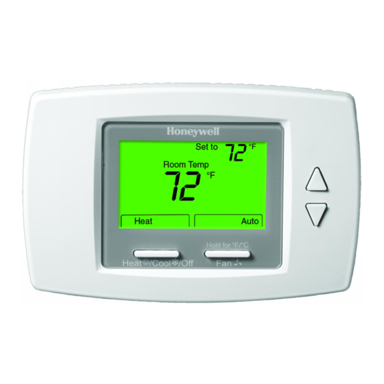
TB6575/TB8575 SuitePRO™
Digital Fan Coil Thermostats
GENERAL
A.
OVERVIEW:
The contractor shall furnish, install, and place in operating
condition an HVAC control system described herein. All units
shall be located in accordance with the plans.
B.
TYPE OF SYSTEM:
System Requirements and Control Provisions:
The SuitePRO™ Digital Fan Coil Thermostats provide the
following
a. Control for 2-pipe fan coil, 4-pipe fan coil (1H/1C), 2-
pipe with auxiliary heat, heat only, or cool only appli-
cations with 3 speed fan.
b. Line voltage control applications (TB6575A,
TB6575B and TB6575C)
– 120 Vac (±10% at 50/60Hz), 240 Vac (-15% to
+10% at 50/60Hz), and 277 Vac (±10% at 50/60Hz).
c. Low voltage control applications (TB8575A) – 20 to
30 Vac at 50/60Hz.
d. Auto Changeover or Manual Changeover control
(selectable in the Installer Setup).
e. 3 speed fan control (Low, Medium, and High).
f.
On/Off heating and cooling relay outputs.
g. Non-programmable user interface with remote
setback input for occupied and unoccupied setpoints
that interfaces with occupancy sensors and time
clocks.
h. Analog pipe sensor or Aquastat® input for 2-pipe
Seasonal Changeover (optional).
i.
Remote wall sensor (optional) - 20K Ohm resis-
tance; uses Honeywell TR-21 and TR21A wall sen-
sors).
j.
VersaSpeed™ fan ramp algorithm automatically
adjusts fan speed (low, medium, and high) on Auto
fan setting, which incorporates Proportional plus
Integral (P+I) control algorithm for precise tempera-
ture regulation.
k. Independent range stops for both heating and cool-
ing setpoints.
l.
Freeze protect algorithm turns on heat when needed
m. Display of room temperature in °C or °F (selectable
in the Installer Setup).
n. Separate cycle rates per hour for heating and cool-
ing modes.
o. Ability to lock out the thermostat keypad (full or par-
tial lockout selectable in the Installer Setup).
p. Pre-wired lead wires on thermostat sub-base for
faster installation (TB6575A, TB6575B and
TB6575C models only).
q. High speed fan startup to ensure sufficient starting
torque.
GUIDE SPECIFICATION
r.
EEPROM permanently retains user settings, includ-
ing setpoints, during power loss (no batteries
required).
s. Energy Saving Options:
(a)Activity Sensing sets back thermostat to
economy mode when there is no activity with
the thermostat (4, 12, or 24 hours selectable).
(b)Remote Setback Inputs receive dry contact
input from a time switch, occupancy sensor, or
hotel card key to set back thermostat to econ-
omy mode.
(c)Auto Fan Reset eliminates the fan from being
run all the time by automatically setting the fan
to auto (2 or 4 hour selectable).
(d)VersaSpeed™ fan ramp algorithm.
(e)Range Stops for heating and cooling.
System Components:
a. TB6575A1000, TB6575B1000, TB6575C1000, and
TB8575A1000 thermostat with sub-base (lead wires
pre-wired to sub-base on TB6575A/B/C models).
b. Wall mount temperature sensors (optional).
c. PS20 (535-34AB08-203) pipe sensor (optional).
d. 50033847-001 adapter plate for mounting on a
vertical 2 x 4 in. single-gang or double-gang NEMA
standard vertical switch box.
C. CODES AND STANDARDS:
The system shall comply with applicable provisions of
ASHRAE 90-75. CSA Certified
C/US for Canada and the U.S.A. Meets the same
requirements as UL-873; FCC Part 15 Class B.
These specifications are based on equipment from Honeywell
to set a standard for design and quality.
D.
WIRING:
All wiring shall meet National Electrical Codes and local
electrical codes.
E.
TESTING GUARANTEE SERVICE:
— Prior to installation, the contractor shall provide copies of
submittals.
— The contractor is responsible for assuring that conduit and
wire quantity, size, and type are suitable for the equipment
supplied.
— Upon completion, the contractor shall conduct a total
system test for the owner and engineer.
— All components, parts, and assemblies supplied by the
manufacturer shall be guaranteed against defects in
materials and workmanship for 2 years.
— Warranty service shall be performed by the contractor.
63-4373-03
Advertisement

Related Manuals for Honeywell SuitePRO TB6575


Summary of Contents for Honeywell SuitePRO TB6575
- Page 1 C/US for Canada and the U.S.A. Meets the same Remote wall sensor (optional) - 20K Ohm resis- requirements as UL-873; FCC Part 15 Class B. tance; uses Honeywell TR-21 and TR21A wall sen- sors). These specifications are based on equipment from Honeywell VersaSpeed™...
-
Page 2: Sequence Of Operations
TB6575/TB8575 SUITEPRO™ DIGITAL FAN COIL THERMOSTATS SEQUENCE OF OPERATIONS AUTO CHANGEOVER (4-PIPE MODE): In 4-pipe Auto Changeover mode, use the Up and Down arrow buttons to change the setpoint. Use the System button to The heating and cooling setpoints shall be individually switch between the heating setpoint and the cooling setpoint. - Page 3 2 x 4 in. single-gang or double-gang NEMA standard vertical switch box. — W6380B1005; Fan Coil Unit Relay Control Center. Aquastat® is a registered trademark of Honeywell International Inc. SuitePRO™ is a trademark of Honeywell International Inc. VersaSpeed™ is a trademark of Honeywell International Inc.
- Page 4 TB6575/TB8575 SUITEPRO™ DIGITAL FAN COIL THERMOSTATS Automation and Control Solutions Honeywell International Inc. 1985 Douglas Drive North ® U.S. Registered Trademark Golden Valley, MN 55422 © 2013 Honeywell International Inc. 63-4373—03 M.S. Rev. 08-13 customer.honeywell.com Printed in United States...