Advertisement
Quick Links
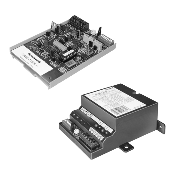
APPLICATION
The Q7002 Interface Modules allow controllers with an
otherwise incompatible signal to control an Economizer Logic
Module or Direct Coupled Actuator.
Copyright © 1998 Honeywell Inc. • All Rights Reserved
Q7002A,B,C Interface Modules
FEATURES
• Available with either enclosure or snap-track mount.
• 24 Vac or 24 Vdc power.
Q7002A Economizer Interface Module
• Accepts the economizer signal from a W7100 or W973.
• Provides an spdt relay output to an Economizer Logic
• Includes LED indication of relay status.
Q7002B Universal Analog Interface Module
• Accepts dc voltage, current, or resistive input.
• Provides either a voltage or current output for an
• Inputs and outputs are jumper-selectable and include
• Output is jumper-selectable direct- or reverse-acting.
• Includes reference voltage and current to power an
Q7002C Pulse-to-Analog Interface Module
• Accepts a pulse-width modulation (PWM) signal.
• User-selectable PWM time base.
• Positive or negative input reference.
• All ranges have 255-step resolution.
• Provides an analog output (either voltage or current)
• Six-hour memory.
• Multiplex mode enables one PWM signal from a
• Inputs and outputs are jumper-selectable and include
Application ......................................................................
Features ..........................................................................
Specifications ..................................................................
Ordering Information .......................................................
Installation .......................................................................
Settings and Adjustments ...............................................
Module (for example: W6215, W7215, and W7460).
actuator.
adjustable zero and span.
input device or sensor.
for an actuator.
Building Automation System (BAS) controller to
address and control up to eight interface modules.
adjustable zero and span.
PRODUCT DATA
Contents
1
1
2
2
4
6
63-2551
Advertisement

Related Manuals for Honeywell Q7002A


Summary of Contents for Honeywell Q7002A
- Page 1 • Inputs and outputs are jumper-selectable and include adjustable zero and span. Contents Application ..............Features ................Specifications ..............Ordering Information ............Installation ............... Settings and Adjustments ..........63-2551 Copyright © 1998 Honeywell Inc. • All Rights Reserved...
-
Page 2: Specifications
Minneapolis, Minnesota 55422-4386 www.honeywell.com/building/components In Canada—Honeywell Limited/Honeywell Limitée, 35 Dynamic Drive, Scarborough, Ontario M1V 4Z9. International Sales and Service Offices in all principal cities of the world. Manufacturing in Australia, Canada, Finland, France, Germany, Japan, Mexico, Netherlands, Spain, Taiwan, United Kingdom, U.S.A. - Page 3 Q7002A,B,C INTERFACE MODULES Action: Output Burden: Direct or reverse acting. 650 ohm maximum (4-20 mA). Ambient Ratings: NOTE: Both outputs (voltage and current) of the Q7002C Temperature Range: 32°F to 158°F (-40°C to 70°C). are active simultaneously. Maximum current Derated Output to: -40°F.
- Page 4 Q7002A,B,C INTERFACE MODULES Table 2. Acceptable Q7002C Inputs and Location Dip Switch Settings. Select a location that meets the ambient temperature ratings. PWM Time NOTE: Installing the device inside a control panel can help Dip Switch Settings B a s e prevent damage.
- Page 5 AND OVERLOAD PROTECTION AS REQUIRED. M13267 PROVIDE DISCONNECT MEANS AND OVERLOAD PROTECTION AS REQUIRED. THE POWER SUPPLY CAN BE 24 VAC (AS SHOWN) OR 24 VDC. M13270 Fig. 2. Q7002A wiring. Fig. 5. Q7002B wiring with 2-wire variable resistance input. 63-2551...
-
Page 6: Settings And Adjustments
6. Set MA SPAN potentiometer to 20 mA. Calibration 7. Set the VOLT ADJ potentiometer to the desired IMPORTANT maximum voltage. The Q7002A is not field-adjustable. NOTE: The device calibrates the minimum voltage Q7002B automatically according to the ratio of mA output extremes. - Page 7 Q7002A,B,C INTERFACE MODULES 5. If voltage output is required, proceed to step 6. Current VOLTS OUT 1-5 Vdc output calibration is complete. 4-20 mA MA OUT 6. Set desired maximum voltage output with the VOLT ADJ potentiometer. 24V PWR (HOT)
- Page 8 Q7002A,B,C INTERFACE MODULES Address Pulse Control Pulse The address pulse signals the modules to either accept or The control pulse carries the signal to adjust the control of the ignore the control pulse. The address pulse matches one of addressed module. Control is based in direct proportion to the the existing pulses (see Table 3).