Table of Contents
Advertisement
Advertisement
Table of Contents

Related Manuals for Yamaha MTX3


Summary of Contents for Yamaha MTX3
- Page 1 Owner’s Manual...
-
Page 2: Table Of Contents
Setting the clock........................16 Using the scheduler ......................16 Connecting via the [GPI] connector ..................17 Using the MTX3 to play audio files saved on an SD memory card ........18 Inserting an SD memory card..................18 Removing the SD memory card..................18 Initializing the MTX3 ...................... - Page 3 MUST be installed correctly. Mismatches or incorrect installa- Yamaha. If a cart, etc., is used, please observe all safety mark- tion may result in overheating and battery case rupture.
- Page 4 Yamaha Corporation of America or its subsidiaries. tion of other electronic devices. Compliance with FCC regu- * This applies only to products distributed by YAMAHA CORPORATION OF AMERICA. (class B) IMPORTANT NOTICE FOR THE UNITED KINGDOM...
- Page 5 [PRESET] display indicates “12” In this case, immediately save cord from the wall AC outlet. the data to external device such as a computer, then have qualified Yamaha service personnel replace • If the device is mounted in an EIA standard rack, carefully read the section “Precautions for the backup battery.
-
Page 6: Getting Started
Thank you for purchasing the Yamaha Matrix Processor MTX3. This manual will help you take full advantage of the superior functionality offered by the MTX3. After you have read the manual, keep it in a safe place for reference when needed. -
Page 7: Introducing The Mtx3
In addition to eight high-quality monaural mic/line inputs and two stereo line inputs, a “YDIF” connection from another MTX3 device can allow up to 16 channels of input. An SD memory card slot for playback is also provided; allowing MP3/WAV audio files saved on the SD memory card to be played back. -
Page 8: Controls And Connectors
[ALERT] indicator When an alert occurs, the [PRESET] display will indicate the alert number and this indicator will blink red. o [POWER] indicator This indicator will light when this device is powered-on. MTX3 Owner’s Manual... -
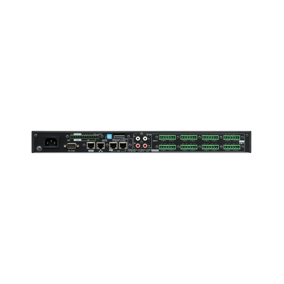
Page 9: Rear Panel
Otherwise, you risk damaging your equipment. Up to eight control panels can be connected to one MTX3. The total length of the cables from the MTX3 to the last con- q AC IN connector trol panel must not exceed 200 meters. -
Page 10: Dip Switches
[INPUT] connectors while phantom power is being used. Switch 6 (IP SETTING) This switch specifies how the MTX3’s IP address will be !2 Cooling vent specified. The MTX3 contains a cooling fan. The cooling air is... -
Page 11: Euroblock Plug Connection
4. For the Euroblock plugs (3-pin) of the [INPUT]/[OUTPUT] connectors, use the included cable ties to fasten the cable to the 1.6 mm or less tab. (1.3 mm for the GPI connector) NOTE Trim off the extra portion of the cable tie as necessary. MTX3 Owner’s Manual... - Page 12 Controls and Connectors 5. Plug the Euroblock plug into the [GPI] con- nector or [INPUT]/[OUTPUT] connector of the MTX3. NOTE When connecting unbalanced cables to the [INPUT] connector, use a jumper wire to connect the “-” and “G” of the Euroblock.
-
Page 13: Quick Guide
This section explains basic settings and connection procedures for constructing an MTX system using the MTX3. Some of the steps may not be necessary for your system; if so, proceed to the next step. 7. The audio signal flow in the MTX3 and the Preparations principal parameters to be set are as follows. -
Page 14: On-Site Work (Installation And Wiring)
A project file with the extension “.mtx” will be created. 4. Set the UNIT ID of the MTX3 and the XMV. Set the UNIT ID for every MTX3 and XMV device you con- nected in the above steps. The UNIT ID is specified by the combination of the [UNIT ID] rotary switch and DIP switches located on each device’s rear panel. -
Page 15: On-Site Work (Settings In Mtx Editor)
13. Save your settings and close MTX Editor. “Online” refers to the state in which the MTX3 itself is con- A project file with the extension “.mtx” will be created. nected with MTX Editor and is synchronized. For details on NOTE how to put the device online, refer to “MTX Editor User’s... -
Page 16: Various Procedures
XMV amps within the same effects from the SD memory card at the date and time you spec- MTX system are stored together as a “preset” in the MTX3 and ify. Each such setting is called an “event.”... -
Page 17: Connecting Via The [Gpi] Connector
+5VDC 100k The MTX3 provides 8 input ports and 4 output ports. Example: Controlling the MTX3 with a 10k ohm • The +5VDC terminals have an output voltage of 5V. The linear taper potentiometer. -
Page 18: Using The Mtx3 To Play Audio Files Saved On An Sd Memory Card
1. Power-off the MTX3. needing to connect a CD player or other audio device. The MTX3 can play back audio files in either MP3 or WAV formats. 2. Set the rear panel DIP switches 7 and 8 to the “INIT. (INITIALIZE)” position. - Page 19 4. When initialization is completed, power-off the MTX3 once again. 5. Set the rear panel DIP switches 7 and 8 to the “RESUME” position. 6. Power-on the MTX3 again. The MTX3 will start up in its factory-set state. MTX3 Owner’s Manual...
-
Page 20: Appendix
SD memory card is not detected Is the SD memory card inserted correctly? Turn off the power of the MTX3, re-insert the card, and then turn the power on again. If the [SD/ACT] indicator does not light and the card is not detected, it may be that the card is damaged. -
Page 21: Alert List
MTX Editor to set the time. The current preset saved in internal mem- Recall the preset. If this does not solve the problem, contact your Yamaha dealer. ory has been lost. The settings saved in internal memory Either the internal backup battery has run low, or the device has malfunctioned. -
Page 22: Specifications
Crosstalk / Channel separation -100dB (@1kHz) [YDIF] connector: 30 meters (Cable length between devices) Maximum cable length [DCP] connector: 200 meters (total cable length from the MTX3 to the last DCP) INPUT PEAK: RED -3dBFS Indicators INPUT SIGNAL: GREEN -40dBFS... -
Page 23: Input/Output Characteristics
Max. before clip Euroblock (Balanced) OUTPUT 1–8 75Ω 10kΩ Lines +4dBu (1.23 V) +24dBu (12.3V) (5.08mm pitch) • In these specifications, 0dBu = 0.775 Vrms. • All output DA converters are 24bit, 128times oversampling. Dimensions Unit: mm MTX3 Owner’s Manual... -
Page 24: Block Diagram
Appendix Block Diagram MTX3 Owner’s Manual... -
Page 25: Index
Euroblock plug ......... 6, 9, 10, 11 event ..............16 Features ..............7 Front Panel .............. 8 Ground screw ............9 INIT. (INITIALIZE) ..........10 Initializing ............... 18 install ..............13 IP address .............. 10 IP SETTING ............10 MTX3 Owner’s Manual... - Page 26 MTX3 Owner’s Manual...
-
Page 27: Important Safety Instructions
WARNING TO REDUCE THE RISK OF FIRE OR ELECTRIC SHOCK, DO NOT EXPOSE THIS APPARATUS TO RAIN OR MOISTURE. (UL60065_03) MTX3 Owner’s Manual... - Page 28 Niederlassung und bei Yamaha Vertragshändlern in den jeweiligen Bestimmungsländern erhältlich. Pour plus de détails sur les produits, veuillez-vous adresser à Yamaha ou au distributeur le plus proche de vous figurant dans la liste suivante. Para detalles sobre productos, contacte su tienda Yamaha más cercana o el distribuidor autorizado que se lista debajo.