Table of Contents
Advertisement
Quick Links
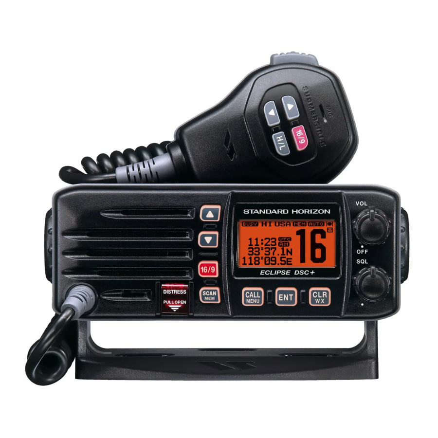
ECLIPSE DSC+ GX1150
25 Watt VHF/FM
Class D DSC Marine Transceiver
Owner's Manual
Replaces older Eclipse+ and Eclipse DSC Models
Meets ITU-R M493-12 regulation
16/9, H/L and channel keys on the mic
DSC test call
Auto DSC channel change selection
Full dot matrix display
Submersible JIS-7 / IPX7 (3.3 feet for 30 minutes)
NMEA 0183 Input and Output
Time and GPS position information shown on display*
Programmable Scan, Priority Scan, and Dual Watch
NOAA Weather Channels with Alert
All USA/International and Canadian Marine Channels
3 Year Waterproof Warranty
When GPS connected
GX1150
Page 1
Advertisement
Table of Contents

Related Manuals for Standard Horizon ECLIPSE DSC PLUS GX1150


Summary of Contents for Standard Horizon ECLIPSE DSC PLUS GX1150
- Page 1 ECLIPSE DSC+ GX1150 25 Watt VHF/FM Class D DSC Marine Transceiver Owner's Manual Replaces older Eclipse+ and Eclipse DSC Models Meets ITU-R M493-12 regulation 16/9, H/L and channel keys on the mic DSC test call Auto DSC channel change selection Full dot matrix display Submersible JIS-7 / IPX7 (3.3 feet for 30 minutes) NMEA 0183 Input and Output...
-
Page 2: Table Of Contents
TABLE OF CONTENTS QUICK REFERENCE GUIDE ..................4 1 GENERAL INFORMATION ................... 6 2 ON-LINE WARRANTY REGISTRATION (in USA or Canada only) ....6 3 PACKING LIST ..................... 7 4 OPTIONS ......................7 5 SAFETY / WARNING INFORMATION ..............7 6 FCC RADIO LICENSE INFORMATION .............. - Page 3 TABLE OF CONTENTS 12 DIGITAL SELECTIVE CALLING ................. 30 12.1 GENERAL ....................30 12.2 MARITIME MOBILE SERVICE IDENTITY (MMSI) ........30 12.2.1 What is an MMSI? ................. 30 12.2.2 Programming the MMSI ............... 31 12.3 DISTRESS ALERT ................... 32 12.3.1 Transmitting a Distress Alert ............32 12.3.2 Receiving a Distress Alert ............
-
Page 4: Quick Reference Guide
/ VOL K Turn the transceiver on and off, and Selects the operating channel. adjust the audio level. SQL K Move this control clockwise to 16/9 B squelch or counter clockwise un- squelch the radio. Press to recall channel 16. Press and hold to recall channel 9. - Page 5 Press to select a VHF or WX channel. CLR / WX B Used to select a desired Press to cancel the menu selection. channel and to select items in Press and hold to recall the last- the DSC OPERATION and used NOAA Weather Channel.
-
Page 6: General Information
1 GENERAL INFORMATION The GX1150 ECLIPSE DSC+ is a VHF/FM transceiver designed for use in the frequency range of 156.025 to 163.275 MHz. The GX1150 can be operated from 11 to 16 VDC and has a switchable RF output power of 1 watt or 25 watts. The GX1150 is capable of DSC (Digital Selective Calling) Class D (indepen- dent Channel 70 receiver) operation which allows continuous receiving of Digi- tal Selective Calling functions on channel 70 even if the radio is receiving a call. -
Page 7: Packing List
3 PACKING LIST When the package containing the transceiver is first opened, please check it for the following contents: GX1150 Transceiver Mounting Bracket and hardware Power Cord with 6 Amp fuse and holder Owner’s Manual Warranty Card 4 OPTIONS MMB-84 ................. Flush-Mount Bracket MLS-310 .............. -
Page 8: Fcc Radio License Information
6 FCC RADIO LICENSE INFORMATION Standard Horizon radios comply with the Federal Communication Commission (FCC) requirements that regulate the Maritime Radio Service. STATION LICENSE An FCC ship station license is no longer required for any vessel traveling in U.S. waters (except Hawaii) which is under 20 meters in length. However, any... -
Page 9: Fcc Notice
Unauthorized changes or modifications to this equipment may void com- pliance with FCC Rules. Any change or modification must be approved in writing by Standard Horizon. NOTICE This equipment has been tested and found to comply with the limits for a Class B digital device, pursuant to Part 15 of the FCC Rules. -
Page 10: Getting Started
8 GETTING STARTED 8.1 ABOUT VHF RADIO The radio frequencies used in the VHF marine band lie between 156 and 158 MHz with some shore stations available between 161 and 163 MHz. The ma- rine VHF band provides communications over distances that are essentially “line of sight”... -
Page 11: Coaxial Cable
8.3 COAXIAL CABLE VHF antennas are connected to the transceiver by means of a coaxial cable – a shielded transmission line. Coaxial cable is specified by it’s diameter and construction. For runs less than 20 feet, RG-58/U, about 1/4 inch in diameter is a good choice. For runs over 20 feet but less than 50 feet, the larger RG-8X should be used. -
Page 12: Emergency (Channel 16 Use)
8.4 EMERGENCY ( CHANNEL 16 USE ) Channel 16 is known as the Hail and Distress Channel. An emergency is de- fined as a threat to life or property. In such instances, be sure the transceiver is on and set to CHANNEL 16. Then use the following procedure: 1. -
Page 13: Making Telephone Calls
channel 16 or 9 for your initial contact. When the hailing channel (16 or 9) is clear, state the name of the other vessel you wish to call and then “this is” followed by the name of your vessel and your Station License (Call Sign). -
Page 14: Installation
9 INSTALLATION 9.1 LOCATION The radio can be mounted at any angle. Choose a mounting location that: • keeps the radio and microphone at least 3.3 ft (1 m) away from your vessel’s magnetic navigation compass • provides accessibility to the front panel controls •... -
Page 15: Optional Mmb-84 Flush Mount Bracket
9.2.2 Optional MMB-84 Flush Mount Bracket 1. To assist in flush mounting, a template has been included. Use this tem- plate to assess the mounting location. 2. Use the template to mark the location where the rectangular hole is to be cut. -
Page 16: Electrical Connections
9.3 ELECTRICAL CONNECTIONS CAUTION Reverse polarity connections will damage the radio! Connect the power cord and antenna to the radio. Antenna and Power Supply connections are as follows (see Figure 1): 1. Mount the antenna at least 1 m away from the radio. At the rear of the radio, connect the antenna cable. -
Page 17: Accessory Cable
9.4 ACCESSORY CABLE Wire Color/Description Connection Examples WHITE - External Speaker ( + ) Connect to external 4 Ohm audio speaker SHIELD - External Speaker (–) Connect to external 4 Ohm audio speaker Connect to NMEA (+) output of GPS BLUE- NMEA Input (+) GREEN - NMEA Common or Ground Connect to NMEA ground of GPS... -
Page 18: Changing The Gps Time
9.6 CHANGING THE GPS TIME From the Factory the GX1150 shows GPS satellite time or UTC time. A time offset is needed to show the local time in your area. 1. Press and hold down the key until “SETUP MENU” appears. 2. -
Page 19: Changing The Time Location
9.7 CHANGING THE TIME LOCATION This menu item allows you to choose to show UTC or the local time which is selected in Section 9.6. 1. Press and hold down the key until “SETUP MENU” appears. 2. Press the key, then select “TIME DISPLAY” with keys. -
Page 20: Controls And Indicators
10 CONTROLS AND INDICATORS Front Panel POWER SWITCH / VOLUME CONTROL ( VOL/PWR ) Turns the transceiver on and off as well as adjusts the audio volume. Turn this knob clockwise to turn the radio on and to increase the speakers audio volume level. - Page 21 Press the key to access the “DSC MENU”. The “INDIVIDUAL CALL”, “GROUP CALL”, “ALL SHIPS CALL”, “POS REQUEST”, “POS REPORT”, “DSC LOG”, and “DSC TEST” functions can be accessed from the “DSC MENU”. NOTE Before the “DSC MENU” menu can be selected a MMSI must be en- tered.
-
Page 22: Rear Panel
Rear Panel DC INPUT CABLE Connects the radio to a DC power supply capable of delivering 12V DC. EXTERNAL SPEAKER CONNECTION CABLE Connects the GX1150 to an external speaker. GPS RECEIVER CONNECTION CABLE Connects the GX1150 to a GPS receiver. GND TERMINAL Connects the GX1150 to a good ground, for safety and optimum perfor- mance. - Page 23 Microphone PTT (Push-To-Talk) SWITCH Keys the transmitter when the trans- ceiver is in radio mode. KEYS keys on the mi- crophone function the same as the keys on the front panel of the transceiver. MICROPHONE Transmits the voice message with reduction of background noise, us- ing Clear Voice Noise Reduction Technology.
-
Page 24: Basic Operation
11 BASIC OPERATION 11.1 RECEPTION 1. After the GX1150 has been installed, ensure that the power supply and antenna are properly connected. 2. Turn the VOL/PWR knob clockwise to turn the transceiver on. 3. Turn the SQL knob fully counterclockwise. This state is known as “squelch off”. 4. -
Page 25: Simplex/Duplex Channel Use
11.4 SIMPLEX/DUPLEX CHANNEL USE Refer to the VHF MARINE CHANNEL CHART (page 70) for instructions on use of simplex and duplex channels. NOTE All channels are factory-programmed in accordance with International, Industry Canada (Canada), and FCC (USA) regulations. Mode of opera- tion cannot be altered from simplex to duplex or vice-versa. -
Page 26: Noaa Weather Alert Test
1. Program NOAA weather channels into the transceiver’s memory for scan- ning. Follow the same procedure as for regular channels under section “11.7 SCANNING.” 2. Press the key once to start memory scanning or priority scanning (deter- mined from the “RADIO SETUP” selection, see page 63 for details). 3. -
Page 27: Memory Scanning M-Scan
CH01A CH88A CH09 CH 68A CH 12 CH 68A CH 15 CH 61A CH18 CH22A ( M-SCAN ) CH01A CH88A CH09 CH 68A CH 12 Priority Channel CH 68A CH 15 CH 61A CH18 CH22A ( P-SCAN ) 11.7.2 Memory Scanning M-SCAN 1. -
Page 28: Priority Scanning P-Scan
11.7.3 Priority Scanning P-SCAN In the default setting, Channel 16 is set as the priority channel. You may change the priority channel to another channel from Channel 16 in the Radio Setup Mode, refer to section “13.5 PRIORITY CHANNEL SET.” 1. -
Page 29: Dual Watch
11.7.5 Dual Watch Dual watch is similar to priority scanning; however instead of multiple channels being selected into memory, only one channel is selected. 1. Select Priority scan mode, refer to section “11.7.1 Selecting the Scan Type.” 2. By default the Priority Channel is set to Channel 16. If you want to select a different channel the radio will Dual Watch to, refer to section “11.7.4 Prior- ity Channel Setting”. -
Page 30: Digital Selective Calling
12 DIGITAL SELECTIVE CALLING 12.1 GENERAL WARNING This radio is designed to generate a digital maritime distress and safety call to facilitate search and rescue. To be effective as a safety device, this equipment must be used only within communication range of a shore- based VHF marine channel 70 distress and safety watch system. -
Page 31: Programming The Mmsi
12.2.2 Programming the MMSI WARNING A User MMSI can be input only once. Therefore, please be careful not to input the incorrect MMSI number. If you need to change the MMSI number after it has been entered, the radio will have to be re- turned to Factory Service. -
Page 32: Distress Alert
12.3 DISTRESS ALERT The GX1150 is capable of transmitting and receiving DSC Distress messages to all DSC radios. The GX1150 may be connected to a GPS to also transmit the Latitude and Longitude of the vessel. NOTE If a GPS with NMEA output is not connected to the radio, the GX1150 will beep 10 minutes after the radio is turned on. - Page 33 Transmitting a Distress Alert with Nature of Distress The GX1150 is capable of transmitting a Distress Alert with the following “Na- ture of Distress” categories: Undesignated, Fire, Flooding, Collision, Grounding, Capsizing, Sinking, Adrift, Abandoning, Piracy, Mob 1. Lift the red spring loaded DISTRESS cover and press the [ DISTRESS ] key.
-
Page 34: Receiving A Distress Alert
Cancel a Distress Alert The GX1150 has the capabil- ity to transmit a DSC Distress cancel call by, pressing the key, then press the key. 12.3.2 Receiving a Distress Alert 1. When a Distress Alert is received, an emergency alarm sounds. The display will show the MMSI (or name) of the vessel transmitting the Distress. -
Page 35: All Ships Call
12.4 ALL SHIPS CALL The All Ships Call function allows contact to be established with other vessel stations without having their ID in the individual calling directory. Also, priority for the call can be designated as Urgency or Safety. URGENCY Call: This type of call is used when a vessel may not truly be in distress, but have a potential problem that may lead to a dis- tress situation. -
Page 36: Receiving An All Ships Call
12.4.2 Receiving an All Ships Call 1. When an All Ships Call is received, an emergency alarm sounds. The display will show the MMSI (or name) of the vessel transmitting the All Ships Call. 2. Press any of the keys on the radio to stop the alarm. 3. -
Page 37: Individual Call
12.5 INDIVIDUAL CALL This feature allows the GX1150 to contact another vessel with a DSC VHF radio and automatically switch the receiving radio to a desired communications chan- nel. This feature is similar to calling a vessel on CH16 and requesting to go to another channel (switching to the channel is private between the two stations). -
Page 38: Setting Up Individual Reply
space to the right press the key. Repeat this procedure until all nine spaces of the MMSI number are entered. 11. If a mistake was made entering in the name or the MMSI number, press the microphone’s key repeatedly until the wrong character is selected, then press the keys to correct the entry. -
Page 39: Setting Up The Individual Acknowledge Message
12.5.3 Setting Up the Individual Acknowledge Message The GX1150 can select either reply message “Able” (default) or “Unable” when the Individual Reply setting (described previous section) is set to “AUTO”. 1. Press and hold down the key until “SETUP MENU” appears. 2. -
Page 40: Setting Up Individual Call Ringer
12.5.4 Setting up the Individual Call Ringer When a Individual Call is received the radio will produce a ringing tone for 3 minutes. This selection allows the Individual Call ringer time to be changed. 1. Press and hold down the key until “SETUP MENU”... -
Page 41: Transmitting An Individual Call
12.5.5 Transmitting an Individual Call This feature allows the user to contact another vessel with a DSC radio and have the radio switch to another channel and ring like a telephone. This feature is similar to calling a vessel on CH16 and requesting to go to another channel. Pre-Programmable Calling 1. - Page 42 Manual Calling You may enter an MMSI number manually to contact without storing it in the Individual Directory. 1. Press the key. The “DSC MENU” will appear. 2. Press the keys to select “INDIVIDUAL”. (To cancel, press the key.) 3. Press the key.
-
Page 43: Receiving An Individual Call
12.5.6 Receiving an Individual Call When receiving an individual call, an acknowledgment must be sent back to the calling station. The GX1150 default setting is Automatic, but has a selection that allows you to manually send a reply before the radio will switch to the requested calling channel. -
Page 44: Call Waiting Directory
12.6 CALL WAITING DIRECTORY The GX1150 logs received Distress Calls and Individual Calls into the Call Waiting Directory for review at a later time. The DSC Call Waiting feature is similar to an answer machine where calls are recorded for review. When a call is logged while the radio is set on the DSC Standby function, a “... -
Page 45: Deleting Dsc Log Calls
6. If you review the DSC Call, press the key again, to call the selected station if de- sired. 7. To exit Call Waiting Directory and return to radio operation mode press the key. NOTE When there is an unread received call, the “ ” icon will appear behind the unread category (“... -
Page 46: Group Call
MMSI numbers. The first digit of a Group MMSI is always set to “0” by International rules. All Standard Horizon radios are preset so when programming a Group MMSI the first digit is set to “0”. -
Page 47: Transmitting A Group Call
6. Press the keys to scroll through the first letter of the group name you want to reference in the directory. 7. Press the key to store the first letter in the name and step to the next letter to the right. 8. - Page 48 6. Press the key again to transmit the Group Call signal. 7. After the GROUP CALL is transmitted, all the radios in the group will switch to the channel which is selected on step 5 above. 8. Press the key to return to radio opera- tion mode.
-
Page 49: Receiving A Group Call
channel you want to communicate on and press key. 9. Press the key again to transmit the Group Call signal. 10. After the GROUP CALL is transmitted, all the ra- dios in the group will switch to the channel which is selected on step 5 above. -
Page 50: Setting Up Group Call Ringer
NOTE When there is an unread Group Call, the “ ” icon will appear on the display. You may review the unread Group Call from the DSC Log, refer to section “12.6.2 Reviewing Received Calls Logged into the Call Waiting Directory.” After a Group call is received, the time the call was made and the ships MMSI or vessels name will appear on the LCD. -
Page 51: Position Request
GX1150. Stan- dard Horizon has taken this feature one step further, if any Standard Horizon GPS is connected to the GX1150, the polled position of the vessel is shown on the display of the GPS chart plotter making it easy to navigate to the location of the polled vessel. -
Page 52: Transmitting A Position Request To Another Vessel
The GX1150 has the capability to turn off the Position Request ringer. 1. Press and hold down the key until “SETUP MENU” appears. 2. Press the keys to select “DSC SETUP” menu. 3. Press the key, then select “DSC BEEP” with the keys. - Page 53 9. If the GX1150 does not receive a reply, the display will be as shown in the illustration on the right. To send again, press the key. NOTE If the GX1150 does not receive position data from the polled vessel, the LCD will show “NO POSITION DATA.”...
-
Page 54: Receiving A Position Request
10. Press any key to stop the alarm. 11. Press the key to show the position from the polled vessel transferred on the display. 12. If the GX1150 does not receive a reply, the display will be as shown in the illustration on the right. -
Page 55: Position Report
12.9 POSITION REPORT The feature is similar to Position Request, however instead of requesting a position of another vessel this function allows you to send your position to an- other vessel. In order to send your position you need to have a GPS receiver connected or to have manually input your position. -
Page 56: Transmitting A Dsc Position Report Call
12.9.2 Transmitting a DSC Position Report Call Pre-Programmable Calling 1. Press the key. The “DSC MENU” will ap- pear in the display. 2. Press the keys to select the “POS REPORT”. 3. Press the key, then press the keys to select the category (“ROUTINE”... -
Page 57: Receiving A Dsc Position Report Call
Press the keys to scroll through num- bers, 0-9. To enter the desired number and move one space to the right, press the key. Repeat this procedure until all nine spaces of the MMSI number which you want to contact are entered. 7. -
Page 58: Dsc Transmission Test
12.10 DSC TRANSMISSION TEST Use the following procedure to ensure the DSC feature are functioning with another DSC radio. 1. Press the key. The “DSC MENU” will appear in the display. 2. Press the keys to select the “DSC TEST”. 3. -
Page 59: Manual Inputting Of The Gps Location (Lat/Lon)
12.11 MANUAL INPUTTING OF THE GPS LOCATION ( LAT/LON ) You may send the Latitude/Longitude of your vessel manually when a GPS receiver is not connected or is not functioning. After the position is entered, transmitting a DSC Distress or Position Send will contain the manually entered position. -
Page 60: Radio Setup
13 RADIO SETUP 13.1 LAMP ADJUSTING Allows adjustment of the backlight intensity or to turn it off. 1. Press and hold down the key until “SETUP MENU” appears. 2. Press the key, then select “DIMMER” in the “RA- DIO SETUP” menu with the keys. -
Page 61: Time Offset
13.3 TIME OFFSET This selection sets the time offset between local time and UTC (time GPS sends to radio). 1. Press and hold down the key until “SETUP MENU” appears. 2. Press the key, then select “TIME OFFSET” in the “RADIO SETUP”... -
Page 62: Time Display
13.4 TIME DISPLAY This selection selects the time display between local time and UTC (time GPS sends to radio). 1. Press and hold down the key until “SETUP MENU” appears. 2. Press the key, then select “TIME DISPLAY” in the “RADIO SETUP” menu with the keys. -
Page 63: Scan Type
13.6 SCAN TYPE This selection selects the scan mode between “Memory Scan” and “Priority Scan.” 1. Press and hold down the key until “SETUP MENU” appears. 2. Press the key, then select “SCAN TYPE” in the “RADIO SETUP” menu with the keys. -
Page 64: Wx Alert
13.8 WX ALERT This section allows the NOAA Weather alert to be customized. 1. Press and hold down the key until “SETUP MENU” appears. 2. Press the key, then select “WX ALERT” in the “RADIO SETUP” menu with the keys. 3. -
Page 65: Maintenance
Occasionally an owner needs a replacement mounting bracket or knob. These can be ordered from our Parts Department by writing or calling (in USA or Canada), or Standard Horizon/Vertex Standard authorized dealers (outside USA or Canada). Marine Division of Vertex Standard US Headquarters 10900 Walker Street, Cypress, CA 90630, U.S.A. -
Page 66: Factory Service
14.2 FACTORY SERVICE In the unlikely event that the radio fails to perform or needs servicing, please contact Marine Division of Vertex Standard (in USA or Canada) or Standard Horizon/Vertex Standard authorized dealers (outside USA or Canada). An “RA” Return Authorisation number is not necessary to send a product in for service. -
Page 67: Channel Assignments
15 CHANNEL ASSIGNMENTS Tables on the following columns list the VHF Marine Channel assignments for U.S.A. and International use. Below are listed some data about the charts. 1. VTS. Where indicated, these channels are part of the U.S. Coast Guard’s Vessel Traffic System. - Page 68 6. Marine vessels equipped with VHF radios are required to monitor Channel 7. 156.050 MHz and 156.175 MHz are available for port operations and com- mercial communications purposes when used only within the U.S. Coast Guard designated Vessel Traffic Services (VTS) area of New Orleans, on the lower Mississippi River from the various pass entrances in the Gulf of Mexico to Devil’s Swamp Light at River Mile 242.4 above head of passes near Baton Rouge.
- Page 69 12. Use of 156.375 MHz is available for navigational communications only in the Mississippi River from South Pass Lighted Whistle Buoy “2” and South- west Pass entrance Mid channel Lighted Whistle Buoy to mile 242.4 above head of Passes near Baton Rouge, and in addition over the full length of the Mississippi River-Gulf Outlet Canal from entrance to its junction with the Inner Harbor Navigation Canal, and over the full length of the Inner Harbor Navigation Canal from its junction with the Mississippi River to its entry to...
- Page 70 VHF MARINE CHANNEL CHART CHANNEL USE D 156.050 160.650 Public Correspondence (Marine Operator) 156.050 Port Operation and Commercial. VTS in selected areas D 156.100 160.700 Public Correspondence (Marine Operator) D 156.150 160.750 Public Correspondence (Marine Operator) 156.150 U.S. Government Only, Coast Guard D 156.200 160.800 Public Correspondence (Marine Operator), Port operation, ship movement 156.200...
- Page 71 VHF MARINE CHANNEL CHART CHANNEL USE D 156.025 160.625 Public Correspondence (Marine Operator) D 156.075 160.675 Public Correspondence (Marine Operator), Port operation, ship movement 156.075 Public Coast: Coast Guard; East Coast: commercial fishing only D 156.125 160.725 Public Correspondence (Marine Operator), Port operation, ship movement 156.125 Public Coast: Coast Guard;...
- Page 72 VHF MARINE CHANNEL CHART CHANNEL USE D 157.025 161.625 Port operation, ship movement 157.025 Commercial D 157.075 161.675 Port operation, ship movement 157.075 U.S. Government Only - Environmental protection operations. 157.075 Canadian Coast Guard Only D 157.125 161.725 Public Correspondence (Marine Operator), Port operation, ship movement 157.125 U.S.
-
Page 73: Warranty
In the event of a defect, malfunction or failure of the Product during the war- ranty period, STANDARD HORIZON’s liability for any breach of contract or any breach of express or implied warranties in connection with the sale of Products... - Page 74 STANDARD HORIZON may, at its option, repair or replace parts or subassemblies with new or reconditioned parts and subassemblies. Parts thus repaired or replaced are warranted for the balance of the original applicable warranty.
- Page 75 Product Support Inquiries If you have any questions or comments regarding the use of the GX1150, you can visit the STANDARD HORIZON Web site to send an E-Mail or contact the Product Support team at 800-767-2450 M-F 7:00-5:00PST. In addition to the warranty, STANDARD HORIZON includes a lifetime “flat rate”...
-
Page 76: Specifications
17 SPECIFICATIONS Performance specifications are nominal, unless otherwise indicated, and are subject to change without notice. 17.1 GENERAL Channels ..........All USA, International and Canadian Input Voltage ................13.8 VDC ±20% Current Drain Standby ....................0.3 A Receive ....................1.0 A Transmit .............. - Page 77 17.3 RECEIVER Frequency Range ............. 156.050 to 163.275 MHz Sensitivity 12 dB SINAD ................. 0.25 µV 12 dB SINAD (70 CH Receiver) ............. 0.25 µV Squelch Sensitivity (Threshold) ............. 0.20 µV Modulation Acceptance Bandwidth ............ ±7.5 kHz Selectivity Spurious and Image Rejection ............–75 dB Intermodulation and Rejection at 12 dB SINAD ......
-
Page 78: Gx1150
17.4 GX1150 DIMENSIONS Page 78 GX1150... - Page 79 This device complies with part 15 of the FCC rules. Operation is subject to the condition that this device does not cause harmful interference. Part 15.21: Changes or modifications to this device not expressly ap- proved by Vertex Standard could void the User’s authorization to operate this device.
- Page 80 Copyright 2010 VERTEX STANDARD CO., LTD. Marine Division of VERTEX STANDARD All rights reserved. US Headquarters No portion of this manual 10900 Walker Street, Cypress, CA 90630, U.S.A. may be reproduced www.standardhorizon.com without the permission of VERTEX STANDARD CO., LTD. Printed in China.