
Related Manuals for Oberheim OB 12


Summary of Contents for Oberheim OB 12
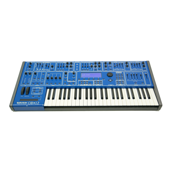
- Page 1 Oberheim VISCOUNT J O I N T V E N T U R E OB 12 Z-Domain Synthesizer MANUALE OPERATIVO OPERATING MANUAL...
-
Page 3: Table Of Contents
OB 12 1. IMPORTANTS NOTES ......................125 1.1 NOTES ABOUT OB-12 ....................125 1.2 NOTES ABOUT THE MANUAL ................... 125 2. MAIN CHARACTERISTICS ....................126 3. CONTROLS AND CONNECTORS ..................127 3.1 THE FRONT PANEL ....................127 3.2 THE CONTROL CENTER SECTION................129 3.3 THE REAR PANEL ...................... -
Page 4: Table Of Contents
OB 12 8.9 EDIT CONTROLLERS ....................186 8.10 WRITE TIMBRE ......................191 9. EDIT PROGRAM ......................... 192 9.1 EDIT PART SETTINGS ....................193 9.2 BUS SETTINGS ......................194 9.3 EDIT EFFECTS ......................194 9.4 EDIT EQUALIZER ......................199 9.5 LINKS ........................... 200 9.6 FOOT CONTROL SETUP .................... - Page 5 OB 12 LOOKING AFTER THE PRODUCT Do not apply excessive force to the structures and controls (knobs, switches). Protect the instrument from stresses both in transit and in use. The instrument should be transported in its original packaging or equivalent wrapping.
-
Page 6: The Front Panel
OB 12 REAL-TIME CONTROL EFFECTIVENESS The OB-12 is a synthesizer designed to be fully controllable in real time, the main feature of the famous analog synthesizers. And the huge advantage this provides is a user-friendliness which was perhaps being lost with the latest digital synthesizers, with programming procedures too complex for many people to attempt. - Page 7 OB 12 1. LFO 1 section This section of the front panel contains the controls relating to the LFO 1 (Low Frequency Oscillator 1). The LFO 1 is the first low frequency oscillator in the generation chain, capable of generating a waveform which modulates the sound cyclically.
-
Page 8: Table Of Contents
OB 12 1. LFO 2 section This section contains the controls relating to the settings of the second low frequency oscillator, controllable by means of the wheel on the left of the keyboard, marked [MODULATION]. 2. KEYBOARD section Here you can adjust a number of parameters relating to the keyboard, including the performance mode, enabling of the Portamento or Unison status and transposition of the oscillators by octaves. -
Page 9: Connections
OB 12 20. Display Backlit liquid crystal display of 240 x 64 pixels for displaying the names of the Programs and Timbres, and all the functions relating to programming of the OB-12. Thanks to this generously sized display, all operations will be easier and learning about the programming parameters will be more intuitive with the aid of specific bitmap or calculated graphic references. - Page 10 OB 12 24. Rotary encoder and [CURSOR] keys The rotary dynamic Encoder allows you to select the Program or Timbre of your choice, to increase or decrease the value of the parameter currently selected or to position the cursor on the chosen field in the option selection menu (e.g.
- Page 11 OB 12 internal programming parameters to these connectors. Connect expression pedals to the [EXP.1] (Expression 1) and [EXP.2] (Expression 2) connectors, and footswitch pedals to the [SWITCH1] and [SWITCH2] ports. 31. [DIGITAL OUTPUT] connector You can use this socket to collect the digital signal generated by the OB-12 in order to connect the instrument to DATs, digital mixers, CD mastering units, etc..
-
Page 12: Mixing Console
OB 12 Connecting the OB-12 to a mixing console will allow you to obtain excellent advantages, with the possibility of using four outputs. For example, you can address the MAIN OUT connectors to two channels (or to one stereo channel) and the AUX OUT connectors to two different channels, so that the signals on the outputs can be processed differently. -
Page 13: Midi Units
OB 12 Essentially, the OB-12 consists of five main sections: The control section consists of the velocity and Aftertouch sensitive 49-key keyboard and the controls on the panel. If the OB-12 is piloted by a Master Keyboard (or by another MIDI controller), the control section is also assumed by the connected MIDI devices. - Page 14 OB 12 In theory a sound (whether an imitation of an acoustic instrument or a completely new, “surreal” sound) can be generated with the aid of just three fundamental circuits: - an oscillator: to generate the basic waveform and control its pitch...
- Page 15 OB 12 The internal memory is mainly subdivided into four large sections: 1. the memory section reserved for the PROGRAMS (and thus the PROGRAM operating environment) 2. the memory section reserved for the TIMBRES (TIMBRE operating environment) 3. the memory section reserved for the SYSTEM UTILITIES (SYSTEM operating environment) 4.
- Page 16 OB 12 OSC ENV: which acts on the oscillators and establishes their behaviour over time, and thus defines how the pitch will change over time; FILTER ENV: which sets how the filters will behave over time and thus how the character of the sound will change over time;...
- Page 17 OB 12 To access this operating environment, press the [SYSTEM] button in the MODE&SET-UP section of the central panel. Once the selection has been made, the LED of the key illuminates and the following video page appears in confirmation: As we will see below, the OB-12 has a huge number of parameters and controls on the front panel, used to generate the type of sound desired.
- Page 18 OB 12 which contains the following settings: ACTS ON PROGRAM: use this parameter to enable the function in Play Program mode (but not in Edit Program mode). FREEZE TIME: here you can set the time for which the video page is to remain on the display before the display again shows the video page present before the Swap (provided the DISPLAY HOLD is not active).
- Page 19 OB 12 [TAP TEMPO]: this button allows you to set the metronome tempo of the arpeggio by pressing the button itself. The LED on the button displays the current metronome tempo, and if the key is pressed twice, the OB-12 will calculate the time between one press and the next in order to set the arpeggio tempo.
- Page 20 OB 12 - RANDOM (RND): the arpeggio notes are played at random. [RANGE]: this button allows you to set the range in octaves of the arpeggio. The ranges available are: - +1: arpeggio range two octaves. - +2: arpeggio range three octaves.
- Page 21 OB 12 [ON/OFF]: this button allows you to activate or deactivate the Phrase Recorder function. The status of the function will be displayed by the LED on the button concerned in accordance with the following rule: - LED on: function active...
- Page 22 OB 12 The PHRASE RECORDER section [TEMPO] trimmer and [TAP TEMPO] button can be used to regulate the metronome tempo for repetition of the Motion. If the Phrase Recorder is already active, the Motion repetition tempo will be affected by the values set for the Phrase Recorder.
- Page 23 OB 12 Once the connections have been made, follow these simple rules to switch on the instrument, in order to prevent malfunctions and/or damage to the OB-12 and the connected instruments: Check that the OB-12 is correctly connected to the rest of the system.
- Page 24 OB 12 As the above illustration shows, the video page contains three folders called SELECTION, INFOS and SCOPE, plus an EDIT field displaying a function. The folder currently selected is SELECTION, since it is open and its contents are shown in reverse. The function buttons beneath the display can be used to select the folder or function in line with the button concerned.
- Page 25 OB 12 As well as playing an entire Program, the OB-12 also allows the user to play the Timbres individually. From any video page, press the [TIMBRE] button in the MODE&SET-UP section of the central panel; the system will leave the Program environment and enable the Timbre present in the Part currently selected.
-
Page 26: Main Structure
OB 12 Using the panel, allowing real time modifications, is one of the main features of the best synthesizers. For this reason, we will first describe all the functions which can be recalled using the controls on the front panel. - Page 27 OB 12 The parameters is: - Sawtooth wave: modification of the SPREAD parameter - Triangular wave: modification of the WRAP parameter - Square wave: modification of the WIDTH parameter these parameters assume the following functions: SPREAD: Defines the degree of deformation of the sawtooth waveform. If the parameter is set with values above zero, the sound will be slightly out of tune;...
- Page 28 OB 12 [LFO1 DEPTH]: regulates the depth of the frequency modulation by LFO1 (first low frequency oscillator) on the pitch (with cyclic variation) of the Osc.1 signal, thus generating vibrato effects. With the knob turned completely to the right, Osc.1 will be affected by the maximum depth of LFO1 modulation.
- Page 29 OB 12 [WAVE SELECT]: you can use these keys to activate/deactivate the waveform associated to them. The LEDs above the keys display the status of the waveform according to the following rule: LED on: waveform present LED off: waveform deactivated [WIDTH]: this trimmer controls the pulse width of the square waveform.
- Page 30 OB 12 - LFO2: the second low frequency oscillator - EG: the envelope generator The selection will be confirmed by illumination of the corresponding LED. N.B.: If you have deleted the square waveform (by means of the [WAVE MIX] slider or the [WAVE SELECT] button referred to this signal) you will not be able to hear any acoustic effect generated by this control.
- Page 31 OB 12 slider ([RING MOD]) balances the signal received from the first slider (i.e. Osc.1+Osc.2) with the Ring Modulator. As the slider is raised the amount of Ring Modulator signal increases. The third slider ([NOISE]) balances the signal received from the second slider (i.e.
- Page 32 OB 12 As we have mentioned when discussing the synthesis technique used by the OB-12, the signal generated by the oscillators is rich in harmonics, or in other words it has a very wide frequency content. The filter can be used to attenuate specific harmonics, or a given range of frequencies, in order to obtain the desired sound (with regard to the timbre quality).
- Page 33 OB 12 CAUTION! Excessively high resonance coefficient values might trigger unwanted oscillations. [ROUTING]: you can use this button to select the type of connection between the two filters, as follows: The selection made will be shown by illumination of the corresponding LED.
- Page 34 OB 12 [ATTACK] : this slider allows you to regulate the attack time of the filter envelope, (Attack Time) meaning the time the sound takes to reach the maximum cut-off frequency when the note has been played. [DECAY] : this slider allows you to regulate the decay time, meaning the time from (Decay Time) when the filter reaches the maximum cut-off frequency to when it reaches the Sustain condition.
- Page 35 OB 12 The amplifier controls the volume of the sound, varying it in relation to time when required. This section allows you to set the envelope which will control the amplifier and the distribution of the sound within the stereophonic panorama.
- Page 36 OB 12 When the [AUTOPAN] LED is off, the trimmer regulates the depth of modulation by LFO1 on the sound volume, thus generating tremolo effects. [AUTOPAN]: this button establishes whether LFO1 is to be assigned to the Pan (i.e. cyclic shift of the signal from right to left);...
- Page 37 OB 12 (sawtooth or ramp): the signal passes (triangular): starting from a minimum immediately from a maximum to a level, the signal rises to a maximum minimum value. value in a given period of time, then returns to the minimum level in the same period of time.
- Page 38 OB 12 This section of the panel allows you to regulate the transposition of the oscillators and the keyboard modes. The section contains the following controls, which as the illustration shows are subdivided into four subsections. PORTAMENTO When the Portamento is active, the pitch (tuning) of each...
- Page 39 OB 12 The Legato function, only available with monophonic keyboard, allows a succession of notes to be played without interruption. This means the attack on the following note is eliminated and only the pitch is changed. [MONO] : this button allows...
- Page 40 OB 12 The OB-12 offers an effects section with which you can add four fully configurable algorithms to your sound. The OB-12 allows you to make use of the following algorithms: OVERDRIVE: simulates an amplifier brought to saturation. Can be used when creating timbres which simulate a guitar.
- Page 41 OB 12 This section allows you to make use of a (mutually exclusive) graphic or parametric equalizer, used to regulate the equalization of the sound. The section relating to the equalizer comprising the following controls: [MID MODE]: defines the type of...
- Page 42 OB 12 [Q]: sets the band-width of operation on the frequency set with the [MID] trimmer. [HIGH]: regulates the enhancement / attenuation of the signal with frequencies higher than 6 KHz. The trimmers which regulate the amount of action on the signal ([LOW], [FREQ] and [HIGH]) operate exactly as described for the graphic equalizer.
- Page 43 OB 12 The KEYBOARD SENSE section contains the controls for enabling and disabling the Velocity and/or the Aftertouch. You can use the Velocity, meaning the dynamic applied to the keyboard keys, to control up to 19 sound generation parameters (see point 8.9), while the Aftertouch, meaning the force applied to the key after it has been depressed, can be used to regulate up to 14 generation parameters (see point 8.9).
-
Page 44: Play Program
OB 12 The Edit Timbre function allows the user to set all the parameters relating to the chain for generation of a given sound. Section 7 “Using the panel” has already illustrated the functions of all the controls needed to create the main parameters of a sound. The display pages allow you to define additional settings for total control of the editing of a timbre. - Page 45 OB 12 they have been described in section 7). Alongside the name (or code) of the parameter whose function is being discussed, in round brackets you will find the full name of the parameter and of the panel control found in the section whose contents are being explained, used to modify the parameter in question.
-
Page 46: Play Timbre
OB 12 you can also annul one waveform (the triangular one, for example) to produce a waveform which is different again: When the OSCILLATOR1 option is selected in the SCOPE video page from PLAY PROGRAM or PLAY TIMBRE, the display will show the sum of the three main waveforms in real time (see point 6.1). - Page 47 OB 12 TRIANGLE STATUS : activates (TRIANGLE ([WAVE SELECT] relating to the waveform concerned) STATUS=ON) / deactivates (TRIANGLE STATUS=OFF) the triangular waveform. TRIANGLE LEVEL : regulates the level of the signal ([WAVE MIX] relating to the triangular waveform) in a range from 0 (signal level zero) to 100 (maximum signal level).
-
Page 48: Edit Timbre
OB 12 opposite signal phase originating from LFO1), 0 (no modulation), +50 (maximum modulation). PWM DEPTH FROM LFO1 (Pulse Width Modulation Depth From LFO1 , [PWM DEPTH] of OSCILLATOR 1 : regulates the depth of modulation of the pulse width (PWM=Pulse With section assigned to LFO1) Modulation) generated by Osc.1 by LFO1. - Page 49 OB 12 As can be seen, the SAW and TRIANGLE video pages differ from those displayed for Osc.1 in that the SAW SPREAD and TRIANGLE WRAP parameters are not present, while the PULSE is identical. Refer to the descriptions of the pages relating to the first oscillator for the information you require.
- Page 50 OB 12 SYNC STATUS : activates (SYNC STATUS=ON) and ([SYNC]) deactivates (SYNC STATUS=OFF) the synchronisation of the waveform leaving Osc.2 with that generated by Osc.1. This means that whenever the Osc.1 waveform returns to its starting point the Osc.2 waveform will also be reset (or returned to its cycle start), thus obtaining a more complex waveform.
- Page 51 OB 12 As we have already described, the waveform leaving the two oscillators is the sum of three basic waveforms, and is therefore a complex waveform. The OSC.COMMON section mixes the two waveforms to create the most widely varying combinations. As well as this, the resulting waveform can be combined with the result of the mixing of Osc.1 with Osc.2 with a Ring Modulator and...
- Page 52 OB 12 BALANCE2 : regulates the quantity of signal obtained from the first ([BALANCE], RING MOD slider) balancing block which will be modulated by the Ring Modulator, in a range of values from 0 (no modulation by the Ring Modulator) to 100 (signal totally modulated by the Ring Modulator).
- Page 53 OB 12 containing the following parameters: OSCILLATOR1 : regulates the depth of the envelope, or the ([ENV DEPTH] assigned to OSC.1) amount by which the pitch of the signal generated by the first oscillator will vary over time, in a range of values of +50 (maximum envelope, i.e. maximum pitch variation), 0 (no envelope, i.e.
- Page 54 OB 12 Naturally, the above diagrams are only an example of the waveform leaving the filter, since as we have seen, the waveforms generated by the two oscillators are much more complex. The OB-12 makes available two filters, with total configuration with regard to their type (low pass, band pass and high pass) and parameters of use.
- Page 55 OB 12 An ADSR envelope is therefore subdivided into: ATTACK Time : the time which passes from when a key is pressed to when the maximum level is reached. DECAY Time : the time taken to pass from the maximum level to the SUSTAIN level: SUSTAIN Level : the level at which the signal remains as long as the key is kept pressed.
- Page 56 OB 12 containing the present parameters: ENVELOPE DEPTH : regulates the depth of the envelope ([ENV DEPTH] of the FILTERS section) applied to the filters in a range of values from +50 (maximum envelope, so maximum variation of the sound timbre), 0 (no envelope, so no variation of the sound timbre) and -50 (maximum negative envelope).
- Page 57 OB 12 this parameter will provide intermediate balances between the quantities of signal sent without distinction to the two filters. SPLIT: connection in which the user can set which signal will be sent individually to the two filters. containing the following parameters: BALANCE: regulates the balancing of the signal from the section specified by means of the FILTER 1 IN and FILTER 2 IN parameters, to be sent separately to the two filters.
- Page 58 OB 12 time taken to reach the DECAY 2 value or the SUSTAIN value (if the DECAY 2 moment of time is not present) from the moment when the maximum cut-off frequency (maximum level of the ATTACK section) is reached. The values available range from 0 (DECAY 1 time annulled) to...
- Page 59 OB 12 The main function of an amplifier is to control the level of the signals received from the oscillators and the filters. Amplifiers may be Voltage Controlled Amplifiers (VCAs) or, as in the OB-12, Digitally Controlled Amplifiers (DCAs). VCAs consist of operational or differential amplifiers, while in the case of DCAs, since all it takes to amplify a digital wave is to multiply its numerical width values by a given factor, amplification is carried out by applying a width modulation to the oscillators.
- Page 60 OB 12 affected by the envelope, in a range of values from 0 (no delay) to 100 (maximum delay). DECAY BREAKP. : sets the Breakpoint value for the DECAY period, divided (Decay Breakpoint) into DECAY 1 and DECAY 2. The Breakpoint value specifies the signal level after which DECAY 2 will start, in a range of values from 0 (signal level zero) to 100 (maximum sound level).
- Page 61 OB 12 PAN L and R: sets the distribution over the stereo panorama of the signal leaving the AMPLIFIER section, and thus of the final Timbre sound. The main function of an LFO (Low Frequency Oscillator) is to generate a low frequency signal which can be used as modulant for the signals leaving the synthesizer’s main blocks, such as the...
- Page 62 OB 12 RATE : regulates the frequency of the signal leaving the LFO1, in a ([RATE] of the LFO1 section) range of values from 0 (minimum frequency) to 100 (maximum frequency). Now select the ENVELOPE folder; the display will show the video page relating to programming...
- Page 63 OB 12 As for LFO1, LFO2 allows you to modulate the signal in the various generation sections of the OB-12 with a low frequency signal. The main feature of the second low frequency oscillator is that the quantity of modulation can be regulated by means of the [MODULATION] wheel on the left of the keyboard.
- Page 64 OB 12 CUTOFF RATIO: sets the cut-off frequency of the filter referred to above, in relation to the frequency of the signal leaving the LFO, specified with the RATE parameter. The values which can be selected are the following: -1/2: filter cut-off frequency half an octave lower than that of LFO2.
- Page 65 OB 12 MODE : this ([MONO] and [LEGATO]) parameter can be used to set the keyboard as polyphonic, by setting the parameter as POLY, or monophonic, by setting it as MONO. The Legato function can also be used by selecting the LEGATO option (in this case, MONO mode will also automatically be selected).
- Page 66 OB 12 DETUNE FINE: regulates the fine transposition of the three timbres in hundredths. This transposition is applied to the timbres as for the DETUNE COARSE parameter. FINE RND INFL. : specifies as a percentage by how much the pitch of the...
- Page 67 OB 12 STATUS : enables (ON) or disables (OFF) control of the generation parameters ([VELOCITY ON]) by means of the Velocity. TYPE: sets the type of dynamic. A fixed dynamic can be obtained by setting the parameters as FLAT, or various dynamic curves can be obtained by selecting CURVE (see next video page illustration).
- Page 68 OB 12 displaying the following parameter: CURVE: displays the name of the dynamic curve (drawn on the left of the display) assigned to the note. The curves are as follows: - LIGHT: Light dynamic response curve, in which the maximum dynamic values are reached quickly.
- Page 69 OB 12 for high pressure values. - DELAYED: Curve which delays the emission of data, which are not generated until high pressures are applied to the key, after which high Aftertouch values are reached easily. - INVERTED: Inverted Aftertouch curves have the same properties as reversed Velocity curves.
- Page 70 OB 12 CONTROLLED CONTROLS ON CONTROLLED CONTROLS ON CONTROLLED CONTROLS ON SELECTIONS SELECTIONS SELECTIONS PARAMETERS PANEL PARAMTERS PANEL PARAMTERS PANEL modulation depth of LFO1 [LFO1 DEPTH] of release time of the [RELEASE] of DISABLED none OSC1 LFO1DP FILT.REL. on OSC.1...
- Page 71 OB 12 After making all the desired settings, you can use the WRITE TIMBRE procedure to save the timbre you have edited in one of the 256 memory locations assigned to the Timbres. From any Timbre environment video page, press the [WRITE] button in the MODE&SET-UP section of the...
-
Page 72: Edit Program
OB 12 As we have already explained in point 5.2, a Program is able to contain up to four Timbres. This is possible because the Program can be divided into Parts, to which a given Timbre, a given portion of the keyboard and a specific function of the pedal connected to the rear connectors can be assigned. - Page 73 OB 12 The main feature of a Program is that it can be subdivided into four Parts, to which one Timbre each is assigned. This allows you to play a multi-timbre Program and also assign the Parts to different zones of the keyboard, in order to obtain different sounds (for example, you can play Parts 1 and 3 in a given zone of the keyboard and Parts 2 and 4 in another position) by simply using the same Program.
-
Page 74: Bus Settings
OB 12 This Edit Program section allows you to assign each individual Part to a given output bus. This enables you to exploit the extraordinary feature of having each single Part on each single connector, guaranteeing easier mixing procedures outside the instrument. -
Page 75: Edit Effects
OB 12 algorithms within the effects chain. As already described in 9.2 – Bus Settings, thanks to this function you can associate the effect of your choice to one or more Timbres, in order to set the configurations best suited to the sound required. - Page 76 OB 12 From the EDIT EFFECT video page select field 2-EFFECTS SETTINGS; the display will show the video page relating to setting of the parameters of the OVERDRIVE effect. This algorithm allows the distortion required to be inserted in the effects chain. Conventional ‘60s- style light distortions can be obtained, but the instrument can also produce powerful sounds typical of contemporary rock music.
- Page 77 OB 12 FEEDBACK: sets the feedback of the processed signal, meaning how much signal leaving the algorithm is to be returned to the input. PRE-DELAY: regulates the delay time for activation of the effect. With short delay times you will obtain a more immediate Chorus; longer Pre-Delay times add an acoustic background effect to the sound.
- Page 78 OB 12 To conclude, selecting the REVERB folder allows you to display the page relating to programming of the Reverb effect. Reverb originates as the sum of the various acoustic reflections produced by a sound in a natural environment. If you clap your hands inside a large reflective environment, such as a church, you will hear a strong resonance which gradually dies away;...
- Page 79 OB 12 Another selection relating to configuration of a Program is the EQUALIZER. This function allows you to make use of an equalizer in order to be able to control the tone of the sound you are producing. One very important functional feature of the Equalizer is the fact that it can be configured as either parametric or graphic.
-
Page 80: Links
OB 12 MID HIGH : enhances / attenuates the signal in the frequency region with centre on 6 ([6K]) KHz. If these equalization parameters (and therefore not TYPE) are set at –12 you will obtain attenuation of the signal of -12 dB; conversely, setting them at +12 will give an enhancement of +12 dB. If the parameters are set at 0, the signals will be unaffected by the influence of the equalizer. -
Page 81: Phrase Recorder
OB 12 To display the video page relating to setting of the Links, select the field 5-LINKS from the EDIT PROGRAM menu. The display will show: This first video page allows you to make Links assigned to LFO1. As the illustration shows, the video page indicates the four Parts in which a Link can be set (to the LFO1 of the Timbre present in the selected Part). - Page 82 OB 12 From the EDIT PROGRAM MENU video page, select field 5-FOOT CTRL. The display will show: This video page allows a given function to be assigned to the foot-switch pedal connected to the PEDALS [SWITCH 1] connector. The parameters displayed are: PART: defines the Part to which the function specified with the FUNCTION parameter refers.
- Page 83 OB 12 containing the following parameters: PART: defines the Part to which the function specified with the FUNCTION parameter refers. When other Parts are selected, the function assigned to the previous Part remains in the memory. FUNCTION: assigns the function to the expression pedal, for the Part specified with the parameter of the same name.
-
Page 84: Arpeggio Function
OB 12 CONTROLLED CONTROLS ON CONTROLLED CONTROLS ON SELECTIONS SELECTIONS PARAMETERS PANEL PARAMETERS PANEL [RESONANCE] of release time of the [RELEASE] of FILT.RES. AMPL.REL. resonance of FILTERS FILTERS AMPLIFIER envelope AMPLIFIER attack time of the [AMOUNT] of FILT.ATTACK AMPL.AMOUNT [ATTACK] of FILTERS... - Page 85 OB 12 MODE : sets the arpeggio mode as follows: ([MODE]) - UP: the arpeggio is performed cyclically from the lowest to the highest note as shown in the diagram: - DOWN: the arpeggio is performed cyclically from the highest to the lowest note as shown in the diagram: - UP &...
- Page 86 OB 12 The parameters displayed perform the following functions: SPLIT KEY: sets the split key for definition of the keyboard section in which arpeggios can be performed. If notes beyond the split point are played, they will not be used for an arpeggio, but will be played normally with the Parts to which the Arpeggio has not been assigned.
- Page 87 OB 12 The PHRASE RECORDER allows musical phrases to be recorded and repeated by simply pressing a keyboard key, which from now on we will call the pilot key . The musical phrase selected will thus be repeated until the key mentioned above is released. If the HOLD function is enabled it will not be necessary to keep the key pressed since the musical phrase will be played even after its release.
- Page 88 OB 12 TEMPO : sets the metronome tempo for performance ([TEMPO] or [TAP TEMPO] of the PHRASE section) of the phrases in a range of 25-250 BPM. If there are MIDI Clock messages on the MIDI [IN] port and its assignment to this function has been enabled (see point 10.3), the value of this parameter will be that specified by the MIDI message.
- Page 89 OB 12 containing the following programming parameters: SET: establishes the Set in which the musical phrase to be recorded will be saved, or which contains the phrase to be modified. TRIGGER NOTE: defines the pilot key, meaning the keyboard key enabled to start the musical phrase.
- Page 90 OB 12 LAYER STAT. : if this parameter is set as PROGRAM, during recording you can (Layer Status) play (but not record) the phrase bearing in mind the Program settings (Part, Split / Layer, Effects, etc...). If TMB-SOLO is selected, the phrase will be played with the Timbre sounds current at that moment.
- Page 91 OB 12 After you have played the musical phrase of your choice, select the DONE option using button [F3] to save the data in the Set, already selected, of the Phrase Recorder memory. The display will indicate that saving is taking place by means of the following video page: The PHRASE EVENT EDITOR allows the contents of the musical phrases recorded with the Phrase Recorder to be shown on the display in the form of note events.
- Page 92 OB 12 You can use the function keys to perform the functions described on the display in relation to the selected note. Therefore, button [F1] enables the CLEAR function, used to delete the selected note event. The display will then request confirmation before proceeding: As the Pop-Up menu states, if the [ENTER] is pressed, the note event will be deleted, while [ESC] will abort the deletion command.
- Page 93 OB 12 The MORPH function allows the sound produced by a Program or a single Timbre to be transformed into another sound generated by another Program or Timbre. During the time, you may listen to all variarions of the “continuous” parameters (like F.1 FREQ. for example) concerning the sound generation creating extraordinary effects.
-
Page 94: Keyboard Transpose
OB 12 The SRC (Source) field indicates the starting memory location (whether referred to a Program or a Timbre), while DST (Destination) displays the destination location. You can use the encoder or the number keypad to set the destination location, since the starting location is automatically set with that active when the function is activated. -
Page 95: Motion Recorder
OB 12 The MOTION RECORDER automation feature present in the OB-12 allows the user to save and repeat as a loop a series of events generated on the sections of the front panel in the form of trimmer and/or slider movements. This allows loops of these events to be played back in order to obtain “continuous modifications”... - Page 96 OB 12 In both cases, to stop playback of the Motion press the relative button. The LED in question will go out to confirm that the function has been disabled. When the playback ends, the sound will have the timbric structure set at the end of the Motion; to restore the original settings, select the Program or Timbre again.
- Page 97 OB 12 We will now see how to record a Motion. From the menu described above, select field 1-RECORD MOTION with button [F1]; the display will show the video page containing the recording parameters: The recording can now be set with the following parameters: LOCATION: sets the location in which the sequence of events to be recorded will be saved, or containing the Motion to be modified.
- Page 98 OB 12 TIME SIGN. : sets the time signature of the recording to be made. The values (Time Signature) available are: 2/4, 3/4, 4/4, 5/4, 3/8, 5/8, 6/8, 7/8, 9/8, 12/8. METR.STATUS : if this parameter is set as ON, the metronome will be audible (Metronome Status) throughout the recording phase.
- Page 99 OB 12 The CURRENT MEASURE parameter shows the numbers of the bars as they pass ((useful during over-recording to allow optimum placing of any added notes), while the TEMPO field indicates the metronome time for the recording. The screen also contains the STOP ([F2]) command for stopping the recording and CLEAR ([F1]) for deleting the data present when the key itself is pressed.
- Page 100 OB 12 The second column indicates the trimmer / slider whose movement has been recorded; The third column displays the value assumed by the control at that moment. The encoder or the [CURSOR] keys can be used to scroll through all the events and select the one you require, setting it in the display zone in reverse.
-
Page 101: Write Program
OB 12 The WRITE PROGRAM function allows a Program to be saved in one of the 256 memory locations assigned to it. To enable the function, press the [WRITE] from any Program environment video page; the display will show: The CURRENT LOCATION field displays the current memory location, and DESTINATION the one where the Program will be saved. -
Page 102: Edit System
OB 12 The SYSTEM operating environment comprises all the functions used for optimum setting of operation of the OB-12. The System functions do not relate to sound generation or Program setting, but this does not make them any less important. - Page 103 OB 12 The purpose of this function is setting of the procedure for reception and transmission of MIDI messages, with consequent definition of the channels. This video page contains the MODE parameter which defines this procedure: by setting this parameter as GLOBAL, you can set the single MIDI channel for reception and transmission of messages using the CHANNEL option.
- Page 104 OB 12 SYS-RT : enables (ON) or disables (OFF) the filter for the System Real Time (System Realtime) messages. You can now select the OUT FLT folder with function key [F2] to display the video page relating to setting of the MIDI filters on outgoing messages. Filtering a message (by setting the filter as ON) means not transmitting it.
-
Page 105: Midi Controls
OB 12 LOCATION TYPE: selects the type of memory location which will be recalled on reception of the PG concerned. If PROGRAM is set Programs will be recalled, while selecting TIMBRE obtains recall of the Timbres. BANK-NUMBER: sets the memory location (the name of which is displayed on the right) which will be recalled on receipt of the PG defined with the PRG RECEIVED parameter. - Page 106 OB 12 NRPN NRPN DATA ENTRY NRPN NRPN DATA ENTRY SECTION PA RAMETER SECTION PA RAMETER LFO 2 DEPTH ON AMP. 0÷127 PART SETTING PART 4 HI-KEY 21÷108 UNISON STATUS 0-64 PART SETTING PART 1 TRANSP. 52÷76 UNISON DETUNE FINE 0÷100...
- Page 107 OB 12 sliders on the front panel can be selected. SECTION (not selectable): displays the section containing the control specified with the SLIDER parameter. CC N. : assigns the Control Change to the control specified with the (Control Change Number) SLIDER parameter.
-
Page 108: Midi Sync
OB 12 This section of the SYSTEM menu allows you to set the parameters relating to the MIDI Clock for synchronisation of the Phrase Recorder, the Arpeggio, LFO1 and LFO2 with remote MIDI units. If, for example, you are using a remote sequencer to control the OB-12 sound generation section and you are also playing on the instrument’s keyboard, by synchronising the Arpeggio or LFO1 or... - Page 109 OB 12 at twice the speed of the signal (for example, the arpeggio tempo or the LFO Rate) with which it is synchronised. The values available range from 0.1X to 10X. Pressing the [F2] function key displays the video page relating to the MIDI Real Time messages...
- Page 110 OB 12 these are the parameters displayed in the video page: STATUS: enables (ON) or disables (OFF) the reception of MIDI Real Time messages. DESTIN. : specifies the system to be controlled by the Real Time commands. The (Destination) possible choices are: MOTION REC1: the Real Time messages control the starting and interruption of Motion 1.
-
Page 111: Bulk Dump
OB 12 The Bulk Dump procedure allows the OB-12’s internal programming data to be sent in the form of exclusive system MIDI messages to the MIDI [OUT] port. This function can be used to send the internal programming of the OB-12 to another analog... - Page 112 OB 12 which displays a progression bar with the relative percentage value of the portion of the data transmitted. Conversely, the [ESC] key can be pressed to abort the Bulk Dump procedure with consequent confirmation in the form of the display: To reload the data in the instrument, connect the transmitter device to the MIDI [IN] port.
- Page 113 OB 12 CONTROLS ON CONTROLS ON SELECTIONS FUNCTIONS SELECTIONS FUNCTIONS PANEL PANEL [LOC2] of DISABLED MOT2 ST/STP No function applied Motion Location 1 start/stop AUTOMATION it cyclically activates and [AUTO] of PROGRAM UP single Program forward Encoder AUTO MORPH disactivates the Auto Morph...
- Page 114 OB 12 CONTROLLED CONTROLS ON CONTROLLED CONTROLS ON SELECTIONS SELECTIONS PARAMETERS PANEL PARAMTERS PANEL [LEVEL/PARAMETER] [LEVEL/PARAMETER] feedback of the of EFFECTS delay to activate of EFFECTS CHOR.FDBK REV.PRDLY processed signal by associates to Reverb associates to PRE- Chorus FEEDBACK of...
-
Page 115: Global Setup
OB 12 The GLOBAL SETUP section allows you to adjust the setting of the instrument’s general parameters, such as the pitch, display adjustment, Swapping function (see point 5.2) and switch-on procedures. To access these functions, from the EDIT SYSTEM MENU select field 7-GLOBAL SETUP; the display will show the first video page relating to the pitch of the instrument: Containing the FREQ. -
Page 116: Tools
OB 12 FREEZE TIME: sets the period of time, in seconds, for which the video page which generated the Swapping is displayed, after which the display will return to display of the previous video page (unless the Display Hold is active – LED of the [DISP HOLD] button on). - Page 117 OB 12 SECTION COPY: sets the section to be copied into the Timbre specified by the TARGET TIMBRE parameter. When the [WRITE] key is pressed, the instrument will show a Pop-Up menu with the request “Are you sure?” to ask for confirmation of the procedure. When the [WRITE] key is pressed again, the copying procedure will be carried out;...
- Page 118 OB 12 displaying the following information: CPU REL.: displays the release version of the CPU software currently installed in the instrument. DATE: displays the date of creation of the CPU software release. DSP REL.: displays the release version of the DSP software currently installed in the instrument.
- Page 119 The OB-12 offers the immense advantage that the internal software packages for the instrument supplied by Oberheim can be installed by just sending the data by means of the MIDI [IN] port. This means you will not have to open the instrument and fit the chip containing the software each time.
-
Page 120: Software Installation
OB 12 If the first software installation has not succeeded (because for ex. of transmission faults), the instrument cannot be switch on in the normal way as in such a case the internal memory content is not the correct one. -
Page 121: Midi
OB 12 WHAT MIDI IS The MIDI (Musical Instrument Digital Interface) allows instruments of different makes and types to communicate with each other by means of this clearly specified protocol of codes. This makes it possible to create systems of MIDI instruments offering much greater versatility and control than would be possible with isolated instruments. - Page 122 OB 12 Note Off: this message is transmitted when the key pressed previously is released. When it is received, the sound of the note of that key is deactivated. Each Note Off message includes the following codes: Note Off : a key has been released;...
- Page 123 OB 12...
- Page 125 MIDI IMPLEMENTATION CHART Oberheim-Viscount OB-12 Date: 04/03/2000 Z-Domain Synthesizer Version: 1.0 FUNCTION ... TRANSMITTED RECOGNIZED REMARKS 1-16 1-16 BASIC DEFAULT 1-16 1-16 CHANNEL CHANGED Mode 3 – 4 Mode 3 – 4 On each part MODE Default CC 126 – 127 CC 126 –...
- Page 126 NOTE: This equipment has been tested and found to comply with the limits for a Class B digital Device, persuant to Part 15 if the FCC Rules. These limits are designed to provide reasonable protection against harmful interference in a residential installation. This equipment generates, uses and can radiate radio frequency energy and, if not installed and used in accordance with the instruction, may cause harmful interference to radio comunications.