Table of Contents
Advertisement
Quick Links
Advertisement
Table of Contents

Related Manuals for Standard Horizon HX751


Summary of Contents for Standard Horizon HX751
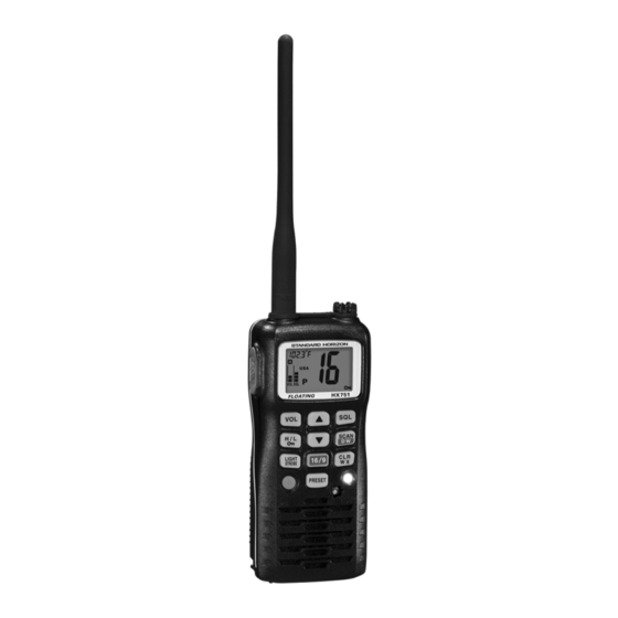
- Page 1 Floating Marine Transceiver Owner’s Manual HX751 Page 1...
-
Page 2: Table Of Contents
GENERAL ........................40 REPLACEMENT PARTS ..................40 TROUBLESHOOTING CHART ................41 10. VHF MARINE CHANNEL ASSIGNMENT ................42 11. WARRANTY .......................... 48 12. SPECIFICATIONS ......................... 51 12.1 GENERAL ........................51 12.2 TRANSMITTER ......................51 12.3 RECEIVER ........................ 51 Page 2 HX751... - Page 3 We appreciate your purchase of the HX751, and encourage you to read this manual thoroughly, so as to learn and fully understand the capabilities of the HX751.
-
Page 4: Rf Exposure Safety Statement
Vertex Standard belt clip for this transceiver, and ensure that the antenna is at least 1 inch (2.5 centimeters) from your body when transmitting. Use only the supplied antenna. Unauthorized antennas, modifications, or attachments could damage the transmitter, and may violate FCC regu- lations. Page 4 HX751... -
Page 5: Fcc And Canada Radio License Information
FCC AND CANADA RADIO LICENSE INFORMATION Standard Horizon radios comply with the Federal Communication Commis- sion (FCC) and Industry-Canada requirements that regulate the Maritime Ra- dio Service. MARITIME STATION LICENSE An FCC ship station license is no longer required for any vessel traveling in U.S. -
Page 6: Fcc Notice
Unauthorized changes or modifications to this equipment may void compli- ance with FCC Rules. Any change or modification must be approved in writing by STANDARD HORIZON, a Marine Division of VERTEX STANDARD. NOTICE This equipment has been tested and found to comply with the limits for a Class B digital device, pursuant to Part 15 of the FCC Rules. -
Page 7: General Information
Battery Life displayed on LCD, and a transmit Time-Out Timer (TOT). The HX751 transmitter provides a full 6 Watt of transmit power and also is selectable to 5, 2.5, and 1 Watt to assist the user in ensuring maximum battery life. -
Page 8: Accessories
A plug), “C” suffix is for use with 230 VAC (Type-C plug), and “U” suffix is for use with 230 VAC (Type-BF plug). Note: Before operating the HX751 for the first time, it is recommended that the bat- tery be charged. Please see section “4.2.3 BATTERY CHARGING” for details. -
Page 9: About This Radio
6. Report the number of persons aboard and condition of any injured. 7. Estimate the present seaworthiness and condition of your vessel. 8. Give your vessel’s description: length, design (power or sail), color and other distinguishing marks. The total transmission should not exceed 1 minute. HX751 Page 9... -
Page 10: Calling Another Vessel ( Channel 16 Or 9 )
Call Sign with each transmission, only at the beginning and end of the contact. Remember to return to Channel 16 when not using another channel. Some radios automatically monitor Channel 16 even when set to other channels or when scanning. Page 10 HX751... -
Page 11: Operating On Channel 13
When channel 67 is used for navigational bridge-to-bridge traffic between ships, Normal, High or Medium power may be used temporarily (in the USA band) by pressing the [ H/L ( )] key. When you select this channel again, the trans- ceiver will revert to low power. HX751 Page 11... -
Page 12: Getting Started
When the battery pack is installed on the transceiver, the terminals that transfer current to the trans- ceiver are not exposed. The terminals that are exposed on the battery pack Page 12 HX751... - Page 13 Battery packs should be charged only in non-hazardous environments; Use only STANDARD HORIZON-approved batteries; Use only a STANDARD HORIZON, (a Marine Division of VERTEX STANDARD) approved charger. The use of any other charger may cause permanent damage to the battery.
- Page 14 Install the Belt Clip as into place. To remove the belt clip you may shown below. find it necessary to use a flat head screw driver to unlock the belt clip from the ra- dio as shown in the image below. Page 14 HX751...
- Page 15 NOTE The CD-39 is only designed for the charging of the HX751’s battery, and is not suitable for other purposes. The CD-39 may contribute noise to TV and radio reception in the immediate vicinity, so we do not recom- mend its use adjacent to such device.
-
Page 16: Controls And Indicators
This section defines each control of the transceiver. For detailed operat- ing instructions, refer to section 6 “BASIC OPERATION”. Refer to illus- trations for the location of the following controls, switches, and connec- tions. HX751 NOTE When transmitting, position your mouth about 1/2 to 1 inch (1.2 ~ 2.5 cm) away... - Page 17 Starts/stops the Memory scanning and Priority scanning on the preset chan- nels and the programmed channels. When Memory scanning, press and hold this key to turn on and off priority scan (“P” icon is shown on the bottom left side of the display during Priority scanning). HX751 Page 17...
- Page 18 (shown as “0” - “9” on the LCD). Pressing this key repeatedly scrolls through the preset memory channels. TX/BUSY Indicator This indicator glows green when a signal is being received and red when transmitting. When the Emergency feature is activated, this indicator blinks the interna- tionally-recognized Morse Code “S.O.S” message. Page 18 HX751...
- Page 19 2.5 cm) away from the small mic hole. Speak slowly and clearly into the microphone. Speaker The internal speaker is located here. Battery Pack Lock ( Bottom side ) Turn the Battery Pack Lock to the “OPEN” position for battery removal. HX751 Page 19...
-
Page 20: Indicators
This indicator shows the channel is in the “Priority Channel”. USA/INTL/CAN Indicator These indicators show the “band” of operation for the particular channel. “USA” indicates the USA band; “INTL” indicates the International band; and “CAN” indicates the Canadian band. Page 20 HX751... - Page 21 ” icon is shown on the LCD, all keys are disabled except for the PTT, [ VOL ] , [ SQL ] , [ POWER ( )] , [ LIGHT ( STROBE )] , and [ H/L ( keys. HX751 Page 21...
-
Page 22: Basic Operation
This state is known as the “Squelch Threshold”. 5. Press the [ ] or [ ] key to select the desired channel. Refer to the channel chart on page 43 for available chan- nels. Page 22 HX751... -
Page 23: Transmission
Before transmitting again, the PTT switch must first be released, then wait 10 seconds and then pressed again. This Time-Out-Timer (TOT) prevents a continuous transmission that would result from an acciden- tally stuck PTT switch. HX751 Page 23... -
Page 24: Usa, Canadian, And International Channels
USA, International or Cana- dian operating band is selected. 6.7 KEYPAD LOCKING In order to prevent accidental channel change, the HX751’s keypad may be locked out. Hold down the [ H/L ( )] key to lock the keypad (except the... -
Page 25: Noaa Weather Channels And Alert
The 1050 Hz tone, when detected, will produce a loud beep in the speaker of the HX751, to signal that a Weather Alert Broadcast is being received. In order to test this system, NOAA broadcasts the 1050 Hz tone every Wednes- day sometime between 11 AM and 1 PM local time. -
Page 26: Preset Channels 0 ~ 9 : Instant Access
1. To start scanning, press the [ SCAN ( DW )] key. 2. To stop the scan, press the [ SCAN ( DW )] or [ CLR ( WX )] key. Page 26 HX751... - Page 27 When the transmission stops the radio will automatically start Prior- ity Preset scan again. During Priority Preset scan the channels will rap- idly change, “P” and “SCN” icon will be shown in the bottom left of the display. HX751 Page 27...
-
Page 28: Memory Scan
5. To stop the Preset Priority Scanning, press the [ SCAN ( DW )] or [ CLR ( WX )] key. 6.10 MEMORY SCAN The HX751 can be programmed to scan channels from a minimum of 2 chan- nels up to all channels in the marine band, PRESET channels and NOAA weather channels. - Page 29 When the transmission stops the radio will automatically start scan again. During Memory Scan, the channels will rapidly change and a “SCN” icon will be shown in the left bottom of the display. HX751 Page 29...
-
Page 30: Priority Scan
Memory Scan operation, if desired. 6. To stop the Priority Scanning, press the [ SCAN ( DW )] or [ CLR ( WX )] key. CH01A CH88A CH09 CH68A CH12 Priority Channel CH68A CH15 CH61A CH18 CH22A Page 30 HX751... -
Page 31: Dual Watch
[ SQL ] key. 3. The “SEt” will appear on the display, indicating that the Menu (“Set”) Mode has been activated. 4. Press the [ SQL ] key to select the Menu item “09 dt”. HX751 Page 31... -
Page 32: Measuring Water Temperature
To return to the Dual Watch operation, repeat the “6.13.1 SETTING UP TRIPLE WATCH FEATURE”, selecting “d-” in step 5. 6.14 MEASURING WATER TEMPERATURE The HX751 can measure water temperature. The measurable temperature range is 14 °F to +140 °F (–10 °C to +60 °C). 6.14.1 ACTIVATING WATER TEMPERATURE SENSOR 1. -
Page 33: Strobe Light
The STROBE feature utilizes the high-intensity strobe LED on the front of the HX751 as a visual distress beacon. The default setting of the Strobe is on continuously, however this may be changed to so the LED blinks the interna- tionally-recognized Morse Code “S.O.S.”... - Page 34 2. The S.O.S. strobe function is interrupted when a signal is received or if the squelch control is turned so audio is heard from the speaker. 3. To disable the S.O.S. strobe function, hold down the [ LIGHT ( STROBE )] key for 1 second again. Page 34 HX751...
- Page 35 MEMO HX751 Page 35...
-
Page 36: Menu "Set" Mode
7. MENU “SET” MODE The HX751’s Menu Mode allows a number of the HX751 operating param- eters to be custom-configured for your operating requirements. The Menu Mode is easy to activate and set, using the following procedure: 1. Turn the transceiver off. - Page 37 The channel shown is the last channel that was received. 09 dt ( DUAL WATCH MODE ) Function: Selects dual or tri-watch as desired. Available Values: d- (Dual Watch) / t- (Triple Watch) Default: d- (Dual Watch) See page 27 for details. HX751 Page 37...
- Page 38 Default: nor (Normal) When “SPL (Special)” is selected the channel shown on the display is the last channel the HX751 received a call on. This is a handy feature if you cannot look at the radio the moment a transmission was received.
-
Page 39: Installation Of Options
2. Insert the FBA-38 into the battery rest on the bottom of the transceiver, and then turn the Battery Pack Lock to the “LOCK” position with a coin. NOTE When the FBA-38 Alkaline Battery Case is used, the HX751 is not able to transmit using 6 W power output. HX751... -
Page 40: Maintenance
9. MAINTENANCE 9.1 GENERAL The inherent quality of the solid-state components in STANDARD HORIZON radios will provide many years of continuous use. Take the following precau- tions to prevent damage to the radio. To prevent corrosion of electrical contacts and keep the water resistance, keep the microphone connected or the jack covered at all times. -
Page 41: Troubleshooting Chart
Hold down the [ H/L ( )] key for 2 Key Lock does not Proper operation not function. followed. seconds. Indicator does not light Defective battery FNB-V99LI. Contact your Standard Horizon when charging a battery. dealer. HX751 Page 41... -
Page 42: Vhf Marine Channel Assignment
5. Channels normally used by recreational boaters are those that include the term “non-commercial” in the Channel Use column of the chart. Some of these are shared with other users and some are used only in certain geo- graphic regions. Page 42 HX751... - Page 43 Mid-channel Lighted Whistle Buoy to mile 242.4 above Head of Passes near Baton Rouge. Additionally it is not available for use in the Mississippi River-Gulf Outlet, the Mississippi River-Gulf Outlet Canal, and the Inner Harbor Navigational Canal, except to aid the transition from these areas. HX751 Page 43...
- Page 44 17. The duplex pair for channel 20 (157.000/161.600 MHz) may be used for ship to coast station communications. 18. Available for assignment to coast stations, the use of which is in accord with an agreed program, for the broadcast of information to ship stations concerning the enviro. Page 44 HX751...
- Page 45 U.S. Government Only D 157.200 161.800 Public Correspondence (Marine Operator) D 157.250 161.850 Public Correspondence (Marine Operator) D 157.300 161.900 Public Correspondence (Marine Operator) D 157.350 161.950 Public Correspondence (Marine Operator) D 157.400 162.000 Public Correspondence (Marine Operator) HX751 Page 45...
- Page 46 Port Operations (Inter-ship only) (1W) 156.875 Port Operations (Inter-ship only) (1W) 156.875 Port Operations (Inter-ship only) D 156.925 161.525 Public Correspondence (Marine Operator), Port operation, ship-movement 156.925 Non-commercial (Recreational) D 156.975 161.575 Port operation and Ship movement 156.975 Commercial Page 46 HX751...
- Page 47 - - - 161.775 Weather (receive only) - - - 163.275 Weather (receive only) NOTE: Simplex channels, 3A, 21A, 23A, 61A, 64A, 81A, 82A and 83A CANNOT be lawfully used by the general public in U.S.A. waters. HX751 Page 47...
-
Page 48: Warranty
STANDARD HORIZON (a division of VER- TEX STANDARD). Include proof of purchase indicating model. serial number, and date of purchase. STANDARD HORIZON will return the Product to the purchaser freight prepaid. Products purchased prior to January 1, 1991 will bear the STANDARD HORIZON warranty terms in effect prior to that date. - Page 49 Products on which the serial number has been removed, defaced, or changed. STANDARD HORIZON cannot be responsible in any way for ancillary equip- ment not furnished by STANDARD HORIZON which is attached to or used in connection with STANDARD HORIZON’s Products, or for the operation of the Product with any ancillary equipment, and all such equipment is expressly excluded from this warranty.
- Page 50 Product Support Inquiries If you have any questions or comments regarding the use of the HX751, you can visit the STANDARD HORIZON Web site to send an E-mail or contact the Product Support team at (714) 827-7600 ext 6300 M-F 7:00- 5:00PST.
-
Page 51: Specifications
Hum & Noise Ratio: 40 dB typical Sensitivity: 0.25 µV for 12 dB SINAD Selectivity: 12 kHz / 25 kHz (–6 dB / –60 dB) 700 mW @16 Ω for 10 % THD (@7.4 V) AF Output (Internal SP): HX751 Page 51... - Page 52 MEMO Page 52 HX751...
- Page 53 MEMO HX751 Page 53...
- Page 54 MEMO Page 54 HX751...
- Page 55 This device complies with part 15 of the FCC rules. Operation is subject to the condition that this device does not cause harmful interference. Part 15.21: Changes or modifications to this device not expressly ap- proved by Vertex Standard could void the User’s authorization to oper- ate this device. HX751 Page 55...
- Page 56 VERTEX STANDARD CO., LTD. Marine Division of VERTEX STANDARD All rights reserved. US Headquarters No portion of this manual 10900 Walker Street, Cypress, CA 90630, U.S.A. may be reproduced without the permission of VERTEX STANDARD CO., LTD. Printed in China Page 56 HX751...