Table of Contents
Advertisement
GE Consumer & Industrial
Power Quality
User Manual
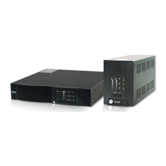
Digital Energy™ Uninterruptible Power Supply
IT Series
-Line Interactive/True Sine Wave UPS
Tower Models
600, 1000, 1500, 2000VA
Rack Mount Models
600, 1000, 1500, 2000VA
GE Consumer & Industrial – Power Quality
Digital Energy™
701 E 22
nd
Street
Suite 300
Lombard, IL 60148 USA
T 800-637-1738
www.geindustrial.com/ups
Modifications Reserved
OPM_ITS_USM_M06_M20_0US_V011 (09/2007)
Advertisement
Table of Contents

Related Manuals for GE 600


Summary of Contents for GE 600
-
Page 1: User Manual
IT Series -Line Interactive/True Sine Wave UPS Tower Models 600, 1000, 1500, 2000VA Rack Mount Models 600, 1000, 1500, 2000VA GE Consumer & Industrial – Power Quality Digital Energy™ 701 E 22 Street Suite 300 Lombard, IL 60148 USA T 800-637-1738 www.geindustrial.com/ups... - Page 2 Version 1.1 Please read these instructions carefully before installation and start-up of the IT Series UPS. Keep this manual in a safe place for future reference. © General Electric Consumer & Industrial. All rights reserved; reproduction without permission prohibited. The content of this manual may be subject to change without prior notice;...
-
Page 3: Table Of Contents
Contents Important safety instructions ..............................1 Save these instructions Safety rules Introduction .......................................2 Introduction Intended use Transport / storage Warranty and RMA process Installation ........................................3 Package contents Installation rules Installation procedure 3.3.1 Placement 3.3.2 Connecting interface devices 3.3.3 Charge the battery 3.3.4 Connect to utility supply 3.3.5... - Page 4 Computer interface USB port configuration Computer Network Security Recommendations Maintenance and Storage ..............................12 Maintenance Storage Conditions Extended Storage Conditions Battery………………………………………………………………….……………………………………………….……………………….. Battery Life Battery Rules Safety precautions Hot Swappable Battery Replacement Tower Procedure Rack Procedure Appendix A: Troubleshooting………………………………………………………………………………………………….. Appendix B: Specifications…………………………………………………………………………….……………………….. Modifications Reserved OPM_ITS_USM_M06_M20_0US_V011 (09/2007)
-
Page 5: Important Safety Instructions
IT Series UPS models. Check your model number by looking at the rear panel of your UPS. While every care has been taken to ensure the completeness and accuracy of this manual, GE accepts no responsibility or liability for any loss or damage resulting from the use of the information contained in this document. -
Page 6: Introduction
2 - Introduction 2.1 Introduction The IT Series is a line interactive uninterruptible power supply (UPS) which generates a true sine wave output, that protects your equipment from power anomalies, including complete power failures. The IT Series UPS is based on microprocessor control. The line-interactive UPS provides pure, reliable AC power to the critical loads - protecting them from utility power blackout, swells, sags, surges and interference. -
Page 7: Transport / Storage
2.4 Warranty and RMA Process GE Consumer & Industrial, operating through its authorized agents, warrants that the standard products will be free of defects in materials and workmanship for a period of twenty-four (24) months after the date of shipment, or such other period as may be specified. Contact the... -
Page 8: Installation Rules
Computer interface connection is optional. The UPS works properly without a computer interface connection. Read the installation instructions provided with computer interface connection and follow accordingly. CAUTION Use only GE factory supplied or authorized UPS RS-232 communication cable! The RS-232 port requires a unique configured communication cable. NOTE Connect one (1) communication cable at a time. -
Page 9: Check The Site Wiring Fault Indicator
3.3.5 Check the site wiring fault indicator (tower mount units) After connecting the load(s) and the UPS to utility power supply, check the site wiring fault indicator on the tower rear panel. The wiring fault indicator (RED) illuminates if the UPS is plugged into an improperly wired AC power outlet. Wiring faults detected include ground, hot-neutral polarity reversal, and overloaded neutral circuit. - Page 10 OVERLOAD indicator (RED LED): The LED illuminates when the loads connected to the UPS exceed the UPS‘s capacity. BACK UP indicator (GREEN LED): The LED illuminates when the UPS is supplying battery power to the loads. REPLACE BATTERY indicator (RED LED): The LED illuminates when the UPS‘s battery is no longer useful and must be replaced. Note: When replacing battery, disconnect the utility power then open the case and take notice of the battery‘s polarity while installing the new battery to avoid short circuits.
-
Page 11: Back Panel
Back panel 600VA Rack mount shown 1500VA Tower shown TELELPHONE/MODEM connector Telecom transfer IN/OUT ports provide users to extend the RJ11 cable applications. CAUTION To reduce the risk of fire, use only No. 26AWG or larger RJ11 telecommunication line cord. OUTPUT POWER RECEPTACLES (NEMA 5-15R) AC INPUT POWER RECEPTACLE (NEMA 5-15P) Modifications Reserved... - Page 12 SNMP adapter card provides real time UPS and power status information for the user. CAUTION Use only GE factory supplied or authorized SERIAL cable! NOTE Connect one (1) communication cable at a time. Do NOT connect (2) two communication cables simultaneously.
-
Page 13: Operation
Operation Switch ON While utility input is connected to the UPS, press the "ON/TEST" button and continue pressing over 0.5 second. Then, connect the electrical cords of the equipment loads to be used (such as computer or monitor) to the output receptacles on the rear panel of UPS. -
Page 14: Shutdown Mode
98SE/ME/2000/XP/2003 server for USB and LINUX. CAUTION Use only GE factory supplied or authorized RS-232 SERIAL cable! To reduce the risk of electric shock, disconnect the UPS from the input (utility) supply before installing a computer interface signal cable. Reconnect the input (utility) supply only after signaling interconnections have been made. -
Page 15: Computer Interface Usb Port Configuration
(Female View) UPS is supplied with a special RS-232 SERIAL cable (that is compatible with DB9 line) socket on the UPS rear panel. That port possesses several signals as explained below: Pin# Function Power Fail: Normally open status, will close when active OUTPUT Reference GND for pin 2 and 5 OUTPUT... -
Page 16: Computer Network Security Recommendations
(Female Type “B” connector View) Computer Network Security Recommendations When configuring devices such as PC servers, clients, gateways, and Intelligent Electronic Devices (including UPS products equipped with data communications capabilities) to interconnect over existing LAN's or other IT infrastructure, it is necessary to take appropriate precautions to ensure the secure and stable operation of these systems and the data that resides on them: •... -
Page 17: Battery
It does not contain CFCs (Chlorofluorocarbons) or HCFCs (Hydro chlorofluorocarbons). GE, in compliance with environment protection recommends to the User that the UPS equipment, at the end of its service life, must be recovered conforming to the local applicable regulations. -
Page 18: Hot Swappable Battery Replacement
1500VA – 3 batteries • 2000VA – 4 batteries • Please call your local GE representative for pricing and availability. Hot Swappable Battery Replacement Tower Procedure - Step 1. Remove front cover panel; pull out from top where finger grooves are located on each side. (See diagrams below) 600 &... - Page 19 600 & 1000VA 1500 & 2000VA Step 3. Remove inside battery cover plate. • 600 & 1000VA Unscrew metal cover plate, Phillips-head screws. Put screws in a safe location for reconnection. (See diagrams below) 600 & 1000VA Modifications Reserved OPM_ITS_USM_M06_M20_0US_V011 (09/2007)
- Page 20 Step 4. Carefully slide batteries out. • 600 & 1000VA - Pull tabs attached to battery out toward front to remove batteries. (See diagram below) 600 & 1000VA • 1500 & 2000VA - Pull tray to remove batteries. (See diagram below) 1500 &...
- Page 21 600 & 1000VA • 1500 & 2000VA – Disconnect Black wire. Disconnect Red wire. Continue to slide batteries out. (See diagrams below) 1500 & 2000VA Step 6. Remove batteries from UPS case. (See diagrams below) 600 & 1000VA Modifications Reserved...
- Page 22 Before inserting the batteries into the unit: Connect the Black and Red Wire on the + terminal as shown in diagrams above. • 600 & 1000VA – Connect the Red Wire on the + terminal as shown in diagram above. • 1500 & 2000VA – Connect the Black Wire on the - terminal as shown in diagrams above.
-
Page 23: Rack Procedure
Step 11. Final connections: • 600 & 1000 VA: Connect the Black Wire as shown in diagram above. • 1500 & 2000 VA: Connect the Red Wire as shown in diagrams above. Step 12. Install Metal Battery cover plate: Install metal plate with Phillips-head screws. - Page 24 600VA & 1000VA 1500 & 2000VA Step 3. Unscrew Left side panel by removing Phillips-head screws. (See diagrams below) 600VA & 1000VA Modifications Reserved OPM_ITS_USM_M06_M20_0US_V011 (09/2007)
- Page 25 1500 & 2000VA Step 4. Remove inside Battery cover plate. Unscrew metal cover plate, Phillips-head screws. Put screws in a safe location for reconnection. (See diagrams below) 600VA & 1000VA 1500 & 2000VA Step 5. Carefully slide batteries out. Pull tray to remove batteries. (See diagrams below) Modifications Reserved OPM_ITS_USM_M06_M20_0US_V011 (09/2007)
- Page 26 600VA & 1000VA 1500VA 2000VA Step 6. Disconnect Wires: Disconnect Black and Red wires. Continue to pull batteries out. (See diagrams below) Modifications Reserved OPM_ITS_USM_M06_M20_0US_V011 (09/2007)
- Page 27 600VA & 1000VA 1500VA 2000VA Modifications Reserved OPM_ITS_USM_M06_M20_0US_V011 (09/2007)
- Page 28 (R e-U se) (R e-U se) (R e-U se) (R e-Use) (Re-U se) (R e-Use) 600 & 1000 VA R ack 1500 VA R ack 2000 VA R ack Step 7. Disconnect Jumper wire(s) and remove batteries. Step 8. Install New Batteries using same battery type and layout as shown in diagrams above.
-
Page 29: Appendix A: Troubleshooting
Press the Non-fuse switch to its "ON" position been opened 800-637-1738 Fault buzzer keeps sounding UPS has internal failure Contact the GE UPS Service Center for help at Alarm continues sounding Overload Remove some load Input circuit breaker on the rear panel... -
Page 30: Appendix B: Specifications
Appendix B: Specifications Rack Model # UPS0600ITSIR UPS1000ITSIR UPS1500ITSIR UPS2000ITSIR Tower Model # UPS0600ITSIT UPS1000ITSIT UPS1500ITSIT UPS2000ITSIT Topology Line Interactive Output VA/Watts 600VA/360W 1000VA/600W 1500VA/900W 2000VA/1200W Output Power Factor Output voltage (Battery Mode) 120V, Pure sine wave at +/-5% of nominal, -10% of nominal after low battery warning Output Voltage (Utility Mode) 120V, +/-10% Output Frequency... - Page 31 20.70 45.64 585x540x290 23.0x21.3x11.4 3.23 UPS1500ITSIR 26.10 57.54 28.80 63.49 585x540x290 23.0x21.3x11.4 3.23 UPS2000ITSIR 28.40 62.61 31.10 68.56 585x540x290 23.0x21.3x11.4 3.23 Note: Characteristics are subject to change without prior notice. Please verify all details with GE. Modifications Reserved OPM_ITS_USM_M06_M20_0US_V011 (09/2007)