JVC VN-T216VPRU Instructions Manual
Fixed hd ip dome camera
Hide thumbs
Also See for VN-T216VPRU:
- Instructions manual (49 pages) ,
- Quick manual (18 pages) ,
- Specifications (3 pages)
Table of Contents
Advertisement
Quick Links
Download this manual
See also:
Quick Manual
Advertisement
Table of Contents

Related Manuals for JVC VN-T216VPRU


Summary of Contents for JVC VN-T216VPRU
- Page 1 FIXED HD IP DOME CAMERA VN-T216VPRU INSTRUCTIONS Thank you for purchasing this product. Before operating this unit, please read the "INSTRUCTIONS", "QUICK GUIDE" and "SAFETY PRECAUTIONS" carefully to ensure the best possible performance. LST1365-001C...
-
Page 2: Table Of Contents
Contents Contents of this manual ..................2 Cautions and Warnings ..................2 FCC Compliance Statement ................3 AVC and MPEG-4 Visual Patent Portfolio License ..........4 AVC Patent Portfolio License ............... 4 MPEG-4 Visual Patent Portfolio License ............4 1 About this Document ....................5 Overview of Contents .................. -
Page 3: Contents Of This Manual
Contents of this manual Windows, Internet Explorer, DirectX and FAT32 are registered trademarks of Microsoft Corporation in the U.S. Pentium is a registered trademark of Intel Corporation in the U.S. NVIDIA and GeForce are trademarks or registered trademarks of NVIDIA Corporation in the U.S. -
Page 4: Fcc Compliance Statement
WEEE (Waste Electrical and Electronic Equipment). Correct disposal of this product (applicable in the European Union and other European countries with separate collection systems). This product should be disposed of, at the end of its useful life, as per applicable local laws, regulations, and procedures. -
Page 5: Avc And Mpeg-4 Visual Patent Portfolio License
AVC and MPEG-4 Visual Patent Portfolio License AVC Patent Portfolio License THIS PRODUCT IS LICENSED UNDER THE AVC PATENT PORTFOLIO LICENSE FOR THE PERSONAL USE OF A CONSUMER OR OTHER USES IN WHICH IT DOES NOT RECEIVE REMUNERATION TO (i) ENCODE VIDEO IN COMPLIANCE WITH THE AVC STANDARD ("AVC VIDEO") AND/OR (ii) DECODE AVC VIDEO THAT WAS ENCODED BY A CONSUMER ENGAGED IN A PERSONAL ACTIVITY AND/OR WAS... -
Page 6: About This Document
1 About this Document This INSTRUCTIONS is designed to be a reference tool for the installation and operation your system including the camera’s features, functions and detailed explanation of the menu tree. Overview of Contents This document contains the following chapters: ... -
Page 7: Product Overview
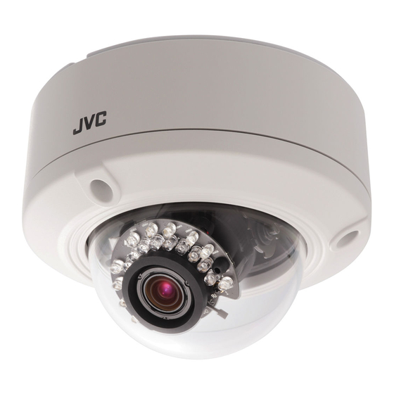
2 Product Overview Camera Parts and Definitions Camera Overview Camera Parts and Definitions The dome camera is fully integrated enclosure with camera and lens. -
Page 8: Routine Maintenance
1 Camera bottom case 3 Loosen the screw to take off camera housing 2 Tilt adjustment bracket and 4 Dome cover thumbnuts, notches(X2) Routine Maintenance * The dome cover is an optical part. Use a soft, dry cloth to remove any fingerprints or dust. - Page 9 Au. IN Audio In Au. OUT Audio out AI. IN Alarm In Alarm Out AI. OUT AC24V Vandal IR dome can operate on AC24V only.
-
Page 10: Installation And Connections
3 Installation and Connections This chapter describes the installation and connection of the camera that can deliver video images and audio in real time using the Internet or an intranet. Before You Begin Please read this guide carefully before you install and operate the camera. Unpack Everything ... - Page 11 When using AC24V power supply, do not connect the AC24V cable to commercial power supply. If it is connected by mistake, the internal circuit may be damaged. Do not use the camera and make sure to send it to the nearest JVC dealer for inspection. Real time clock ...
-
Page 12: Camera Installation
Camera Installation All the installation and operations here should conform to your Note local electricity safety rules. Disassembling the camera Gently remove the screw to take off camera housing (3). Set the camera housing (4) aside. Connecting the Wiring Connect the power supply cable to the power connectors. - Page 13 Washer (for Wire) Screw (for Wire) Safety Wire (Fall Prevention Wire, not supplied) Connect the wiring then place the camera to a proper position by pushing the button.
-
Page 14: Adjusting The Camera Position
Adjusting the Camera Position The dome camera has three axes for positioning the camera. While monitoring the picture on the monitor, adjust the camera position as follows: Pan Adjustment (A) For Wall Mount and Tilted Ceilings: Rotate the lens base (maximum360°) until you are satisfied with the field of view. -
Page 15: Mounting The Camera
Mounting the Camera Place the guide pattern sticker (supplied) on the mounting surface and mark three holes according to the guide pattern sticker. Then fasten the sticker to the mounting surface with screws. Connect the Safety Wire (Fall Prevention Wire, not supplied) to the camera and the ceiling. - Page 16 To prevent the camera from falling off, ensure that it is connected to a firm place (ceiling slab or channel) using a Safety Wire (Fall Prevention Wire is not supplied). Pay also careful attention to the length, strength, wiring, and Warning material (insulating properties) of the fall prevention wire to be used.
-
Page 17: Locking The Camera
This mounting kit is optional accessory. Depending on the material of your mounting surface, you may Note require different screws and anchors than those supplied. If tilt angle is less than 20 degrees from the horizontal, the image can flash by reflection of IR-LED light. Keeping tilt angle over 20 Note degrees is recommended when IR-LED light is used. -
Page 18: Network Camera Diagram
Network Camera Diagram Connection type 1: Connection type 2: Hardware/Software Requirements Computer Windows XP or Windows 7 as OS Internet Explorer Version 6.0-9.0 CPU: Intel Pentium 4 2.4 GHz or equivalent AMD Memory: 1G or above Display adapter Support DirectX9 for example NVIDIA GeForce 6 Series above ATI Mobility Radeon 9500 above. -
Page 19: Connecting The Camera To A Personal Computer
Command Prompt.) Type “Ping 192.168.0.2”. If the message “Reply from…” appears, it means the connection is done. 4. Start Internet Explorer and enter IP address: 192.168.0.2. A login window will appear. Enter the default user name: admin and password: jvc to log in. - Page 20 Figure 3-1 Log on Screen 5. Images of the camera can be viewed through Internet Explorer. Before viewing, follow these steps to enable the display. a. Enable Cookies as shown below: In Internet Explorer, click Internet Options on the Tools menu. ...
- Page 21 In Windows 7 only, Click【Tools】【Internet Options】【Security】 Enable Protected Mode (require restarting Internet Explorer) Unchecked...
- Page 22 Click【Tools】【Internet Options】【Security】【Custom level】 Modify the configuration of IE’s security setting as follow: 【Download signed ActiveX controls】 Prompt (recommended) 【Download unsigned ActiveX controls】 Prompt 【Initialize and script ActiveX not marked as safe for scripting】 Prompt...
- Page 23 【Automatic prompting for ActiveX controls】 Enable 【Run ActiveX controls and plug-ins】 Enable 【Script ActiveX controls marked safe for scripting*】 Enable 6. Type your setting IP address into the browser. 7. Then you should be able to see the camera image screen.
-
Page 24: Overview Of Navigation And Controls
4 Overview of Navigation and Controls Live View Live view is designed for general users to control the camera. In the left list it displays: Full Screen: Set Full screen One shot: take a picture from live view ... -
Page 25: Image Parameters
Image Parameters You can setup Basic Setting, Image Compression, Alarm, FTP, E-mail, SD. Recording and Audio for your network IP camera by clicking on network setting on setting menu. Basic Figure 4-1 Basic... - Page 26 Image Color Automatic Exposure Figure 4-2 Automatic Exposure Automatic Exposure controls the light intensity of picture. There are four types for adjustment. You can select Manual, AES (Automatic Electronic Shutter), Flicker-free 50Hz and Flicker-free 60Hz for the camera depending on your application conditions.
- Page 27 Figure 4-4 Brightness adjustment, Contrast, Saturation Shutter Speed Figure 4-5 Shutter Speed Set desired Shutter Speed from 1/25s to 1/10000s. When video type is PAL, the Shutter Speed can be set at 1/25, 1/50, 1/100, 1/120, 1/150, 1/200, 1/300, 1/500, 1/750, 1/1500, 1/5000 and 1/10000s. When video type is NTSC, the Shutter Speed can be set at 1/30, 1/60, 1/100, 1/120, 1/150, 1/200, 1/300, 1/500, 1/750, 1/1500, 1/5000 and 1/10000s.
- Page 28 R Gain, B Gain & D Gain Figure 4-8 R Gain, B Gain & D Gain Set manual gain value of R Gain, B Gain, and D Gain from 0 to 255. This function is applied for manual lens only. The red(R) gain is used to adjust the red color of the viewing image.
- Page 29 Back Light Compensation is a function that achieves the brightness of whole area to an optimum image level. Due to the intense light coming from the back of objects in the area expected to view, areas desired to see become dark and invisible.
-
Page 30: Compression
Compression Select Compression. Configure the options as described in the table below. Click Save. Dual streams: Both Encoder No.1 & No.2 are available for selection. Functions of MJPEG, MPEG-4 and H.264 are effective. The video signal sent to the Web-Client from the camera has a number of settings that can be edited which affects the video as it’s displayed in the Web-Client. - Page 31 Table below elaborates the above figure. Table 4-1 Compression Compression Item Function Choice Remark Encoder No.1 MJPEG Compression MPEG4 Set a default compression mode. Format H.264 1080P 720P 1080P is the highest resolution and, QVGA is the lowest Resolution 4CIF resolution.1080p only support H.264.
- Page 32 MJPEG : 3-90 ; Quality value Selectable MPEG4 & H264 : 1-31 256K It’s optional only when constant bit 512K rate is chosen. Select the desired bit rate including 256K, 512K, 1M, Bit Rate 2M, 3M, 4M, 6M and 8M b/s. When resolution is not 1080P or 720P, 4M is the maximum.
- Page 33 Table below elaborates the above figure. Table 4-2 Compression Compression Item Function Choice Remark Encoder No.2 MJPEG MPEG4 Compression Set H.264, MJPEG or MPEG4 as a Format default compression mode. H264 no streaming 1) Encoder No.1: 720p; Encoder No.2: D1, 640x360, QVGA. 2) Encoder No.1: VGA, QVGA;...
- Page 34 256K 512K Select the desired bit rate including Bit Rate 256K, 512K,1M, 2M, 3M, 4M b/s. Select the GOP (Group of pictures) number from 1 to 30.If the number is bigger, recovery of the lost frames will be more difficult; If the number is smaller, it will increase the bite rate 1-30 obviously and aggravate the network...
- Page 35 Table 4-3 Compression correlations of resolution and stream...
- Page 36 Table 4-4 Lower frame rate limitation for H.264 and MPEG4 When choosing CBR, some conditions will be disabled based on different resolution setting. Bit Rate vs Frame Rate (Resolution=1080P, 720P) Frame rate Bit Rate 512K 256K Bit Rate vs Frame Rate(Resolution<=D1) Frame rate Bit Rate 512K...
-
Page 37: Mask Zone
Mask Zone Enable button “ON”, then click “Set Mask Zone” to start mask setting. Use mouse to drag a mask rectangle on the screen, click “OK” to complete the selection. Click “Save” to enable the mask setting. Figure 4-15 Mask Zone Note: Max 4 masks can be set on the screen. -
Page 38: Alarm
Alarm External Digital Input 1 When alarm input is connected, the camera triggers an alarm only when the normal state (open or closed) changes. Connect external devices such as sirens or flashing lights to the alarm output connector to signal users of the camera that an alarm is activated. -
Page 39: Sd Recording
Figure 4-18 Alarm Output Figure 4-19 Output Hold Time Please click the “Save” button to save your settings. You can also click the left button “Reset to Default” to set all the data and Note options as defaults. SD Recording Confined SD recording priority: alarm >... -
Page 40: E-Mail Notification
Users can choose recording conditions between Event and Network Loss. When users select “Event”, 2 more selections will be effective and Recording Time can be selectable in 5s, 10s, 15s, 20s, 25s, 30s, 35s, 40s, 45s, 50s, 55s or 60s. SD Free Capacity It shows the free capacity of the SD card. - Page 41 Figure 4-22 Motion detection Settings Email Server Settings Authentication Settings Figure 4-23 Email Server Settings Select an authentication type. 1. No Authentication: no restrict rule 2. SMTP: Simple Mail Transfer Protocol (SMTP) is an Internet standard for electronic mail (E-mail) transmission across Internet Protocol (IP) networks. 3.
- Page 42 Figure 4-25 Email Information Mail to This function is designed to send multiple users when the alarm in or motion detection function is set. Figure 4-26 Mail to If “Send to Administrator” is set to “ON” when a motion happens, the E-mail server will always send a mail to the administrator.
-
Page 43: Audio
Audio You can set up your audio setting by enabling audio input and output. Figure 4-27 Audio Settings Audio Input Audio Input: Set to "ON" when receiving audio from a Line in connected to the camera. Audio Input Level: Select among High, Mid and Low. Figure 4-28 Audio Input Audio Output ... - Page 44 When enabled audio output to “ON”, there are audio issue of the sound is disconnected under a few part of Windows 7 environments. In order to solve audio issue, we suggest to you change a driver settings as follows. 1. Jumbo Frame -->...
-
Page 45: Network Settings
Network Settings Basic Basic Figure 4-30 Network basic Network IP Address: Input your IP address here when you select “Manual”. Subnet Mask: Please use default number: 255.255.255.0. If the subnet mask is not properly configured, the camera may not be able to communicate with other devices on the network. -
Page 46: Ftp Server
ID>:<Password>@<ip-address> in Windows Explorer, then you will find the SD recording result. When you’re visiting the SD The original setting is ftp://admin:jvc@192.168.0.2 recording files, date and time of record refers to the folder’s and file’s name. Figure 4-31 FTP Sever Settings Please click the “Save”... - Page 47 Figure 4-32 Authentication Encoder No.1 & Encoder No.2 Encoder No.1 & Encoder No.2 Figure 4-33 Please choose desired options and value and remember to click “save” button to save all your settings. Note: RTSP URIs for Encoder No.1 & Encoder No.2 are: rtsp://(ip address):(port1)/ livestream rtsp://(ip address):(port2)/...
-
Page 48: Https
When you use Multicast, please set the Default Gateway on Note Network setting. Https Figure 4-34 Certificate File Upload Users can upload certificate here: Click “Browse”, it will pop out a window then you can choose the file that you want to upload ONVIF Figure 4-35 ONVIF There’re 2 ONVIF Modes for your selection:... -
Page 49: Admin Function
ID and password controller. However, User1~5 are allowed to review the live picture only. Without authorization, any operation will be forbidden. The default guest’s login name and password are “user” and “jvc”. Enter a guest’s User ID in the User ID field. ... -
Page 50: Date/Time
Finally, click Save to save the settings. Figure 4-38 Reset Date/Time Set Display and Synchronization Mode Figure 4-39 Date and Time The user can choose Synchronization Mode here from three different types. Set Date and Time Manually Set up the camera’s date and time in the Set Date and Time Manually field. Figure 4-40 Set Date and Time Manually Set Date and Time by NTP Server 1. -
Page 51: Update
Daylight Figure 4-42 Daylight Daylight Saving Select “ON” to activate the daylight-saving function if you are in a daylight saving time zone (effective for NTP mode only), and then choose the starting time ,ending time and time adjustment. Please click the “Save” button to save your settings. You can also click the left button “Reset to Default”... -
Page 52: Set To Factory Default
Figure 4-44 Video Type Note: Analog video output is not available. Import Configuration Settings This function is designed to upload configuration setting from the client computer to network cameras. Figure 4-45 Import Configuration Settings Export Configuration Settings This function is designed to export configuration settings to the client computer. Figure 4-46 Export Configuration Settings Set to Factory Default This function is designed to reset all configuration settings into factory default. -
Page 53: Event Log
Event Log Click the buttons to display the desired logbooks or to delete all logs. Figure 4-49 Log Browse This window is sample. Information FW version and MAC address will be shown. Figure 4-50 FW version and MAC address The displayed numbers are sample. -
Page 54: Miscellaneous
- Important Notice concerning the Software The Software contained in this product, among others, consists of the following software: (1) the software which is developed by or for JVC KENWOOD Corporation; (2) the software which is licensed under the below;... - Page 55 ************************************************************************* * Copyright (c) University of Delaware 1992-2011 * Permission to use, copy, modify, and distribute this software and * its documentation for any purpose with or without fee is hereby * granted, provided that the above copyright notice appears in all * copies and that both the copyright notice and this permission * notice appear in supporting documentation, and that the name * University of Delaware not be used in advertising or publicity...
- Page 56 31. [34]Craig Leres <leres@ee.lbl.gov> 4.4BSD port, ppsclock, Magnavox GPS clock driver 32. [35]George Lindholm <lindholm@ucs.ubc.ca> SunOS 5.1 port 33. [36]Louis A. Mamakos <louie@ni.umd.edu> MD5-based authentication 34. [37]Lars H. Mathiesen <thorinn@diku.dk> adaptation of foundation code for Version 3 as specified in RFC-1305 35.
- Page 57 * 3. All advertising materials mentioning features or use of this software must display the following acknowledgment: * "This product includes software developed by the OpenSSL Project for use in the OpenSSL Toolkit. (http://www.openssl.org/)" * 4. The names "OpenSSL Toolkit" and "OpenSSL Project" must not be used to endorse or promote products derived from this software without prior written permission.
- Page 58 acknowledgement: * "This product includes cryptographic software written by Eric Young (eay@cryptsoft.com)" * The word 'cryptographic' can be left out if the routines from the library being used are not cryptographic related :-). * 4. If you include any Windows specific code (or a derivative thereof) from the apps directory (application code) you must include an acknowledgement: * "This product includes software written by Tim Hudson (tjh@cryptsoft.com)"...
- Page 59 Any and all copyrights and other rights pertaining to the Licensed Software and related documents shall belong to JVC KENWOOD Corporation or the original holder of the right who granted to JVC KENWOOD Corporation the license or sublicense for the Licensed Software (hereinafter the "Original Rightholder"), and the User shall...
- Page 60 JVC KENWOOD Corporation. Article 8 Termination In case the User falls under any of the events described in the following items, JVC KENWOOD Corporation may immediately terminate this Agreement or claim that the User compensates for the damage incurred by JVC KENWOOD Corporation due to such event: (1) when the User violated any provision of this Agreement;...
- Page 61 Agreement shall be provided or settled upon good-faith consultation between JVC KENWOOD Corporation and the User. 3. JVC KENWOOD Corporation and the User hereby agree that this Agreement is governed by the laws of Japan, and any dispute arising from, and relating to the rights and obligations under, this Agreement shall be submitted to the exclusive jurisdiction of the Tokyo District Court for its first instance.
-
Page 62: Specifications
5 Specifications Operational Specifications Image device 1/2.7-type Mega-pixel CMOS sensor Sensitivity Color: 0.6 lx, B/W: 0 lx (50%) Day/Night True D/N IR-LED Yes (IR Distance 15 m) Auto Gain Control Off/On, selectable Auto Iris Control AES (Automatic Electric Shutter) White Balance ATW (2800K~8500K) and Manual PAL: 1/25~1/10000 sec Electric Shutter... - Page 63 IP Specifications Video Compression H.264 & MPEG4 & MJPEG Single Encode: 1080P (max.) Video Streaming Dual Encode: 720P + D1 (max.) NTSC: 1080P(1920 x 1080), 720P(1280 x 720), D1(720 x 480), 4CIF(704 x 480), VGA(640 x 480), 640 x 360, CIF(352 x 240), QVGA(320 x 240) Resolution PAL: 1080P(1920 x 1080), 720P(1280 x 720), D1(720 x 576), 4CIF(704 x 576), VGA(640 x 480),...
- Page 64 Network: RJ45 connector Connectors Audio In/out: removable terminal block Alarm In/out: removable terminal block Environmental Operating -10 °C to 50 °C Temperature Operating Humidity 20 % to 90 % Storage Temperature -20 °C to 60 °C © 2012 JVC KENWOOD Corporation...