Dell PowerEdge M1000e Technical Manual
Modular blade enclosure
Hide thumbs
Also See for PowerEdge M1000e:
- Configuration manual (232 pages) ,
- Getting started (224 pages) ,
- Reference manual (135 pages)
Table of Contents

Related Manuals for Dell PowerEdge M1000e


Summary of Contents for Dell PowerEdge M1000e
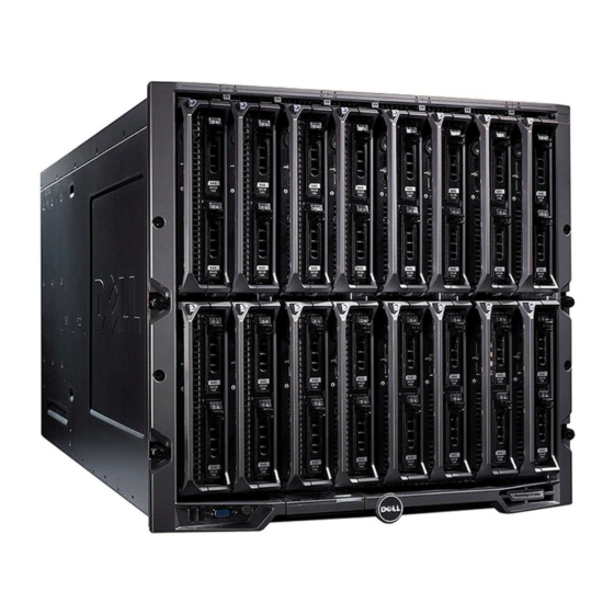
- Page 1 PowerEdge M1000e Technical Guide Built from the ground up to combat data center sprawl and IT complexity, the PowerEdge M1000e enclosure delivers one of the most energy-efficient, flexible and manageable blade server products on the market.
- Page 2 Dell disclaims proprietary interest in the marks and names of others. ©Copyright 2013 Dell Inc. All rights reserved. Reproduction or translation of any part of this work beyond that permitted by U.S. copyright laws without the written permission of Dell Inc. is unlawful and strictly forbidden.
-
Page 3: Table Of Contents
Table 3. FlexAddress features and benefits ........................33 Table 4. 2360W power supply ............................37 Table 5. 2700W power supply ............................38 Table 6. Supported power supply redundancy options ..................... 39 Table 7. Grid redundancy ..............................40 PowerEdge M1000e Technical Guide... - Page 4 Figure 33. System Management Architecture Diagram ....................59 Figure 34. Web interface for the chassis management controller ................61 Figure 35. Chassis management controller........................62 Figure 36. M1000e iKVM ..............................64 Figure 37. Front keyboard/video ports ..........................65 PowerEdge M1000e Technical Guide...
-
Page 5: Blade Enclosure Overview
I/O consumption. Plus, Dell’s FlexIO modular switch technology lets you easily scale to provide additional uplink and stacking functionality — no need to waste your current investment with a “rip and replace” upgrade. -
Page 6: Key Technologies
Key technologies The PowerEdge M1000e is designed to help you be more efficient with time, power and cooling, investment, and system performance. It is a breakthrough Dell-engineered and patent-pending design that maximizes flexibility, power and thermal efficiency, system-wide availability, performance and manageability. The chassis integrates the latest in management, I/O, and power and cooling technologies in a modular, easy-to-use package. - Page 7 Up to six hot-pluggable, redundant power supplies and nine hot-pluggable, N+1 redundant fan modules System front control panel with LCD panel, two USB keyboard and mouse connections and one video crash-cart connection Support for Dell EqualLogic™ PS-M4110 Blade Array with seamless integration into the M1000e chassis PowerEdge M1000e Technical Guide...
-
Page 8: Blade Enclosure Specifications
The chassis architecture is flexible enough for various types of front-loading modules such as servers and storage. Dell server modules are accessible from the front of the M1000e enclosure. At the bottom of the enclosure is a flip-out, multiple-angle LCD screen for local systems management configuration, system information and status. -
Page 9: Table 1. Technical Specifications
Table 1 lists the technical specifications for the PowerEdge M1000e blade enclosure. For the latest information on supported features, visit Dell.com/PowerEdge. Table 1. Technical specifications Feature Parameter Chassis Form factor: 10U modular enclosure holds up to 8 full-height, 16 half-height, or... - Page 10 Ethernet to servers, 40Gb Ethernet to top-of-rack switches, Fibre Channel 8Gb, and InfiniBand QDR/FDR10/FDR. Dell’s blade Ethernet devices also have FlexIO technology, providing on-demand uplink scalability and investment protection unrivaled in the blade server market. Dell PowerEdge M I/O Aggregator Supports Active System Manager and CMC Aggregator GUI.
- Page 11 DPSE functionality that can help lower overall system power consumption by ensuring power supplies run at their optimal efficiency points Fan speed control using Dell’s enhanced efficiency technologies to ensure fans are delivering optimal cooling while minimizing power consumption and airflow ...
-
Page 12: Blade Enclosure Views And Features
3 Blade enclosure views and features The Dell M1000e supports up to 32 quarter-height, 16 half-height, or 8 full-height server modules. The chassis guide and retention features are designed such that alternative module form factors are possible. The chassis architecture is flexible enough that server, storage, or other types of front- loading modules are possible. -
Page 13: Figure 3. M1000E Lcd Panel In Recessed Position
A deployment setup wizard that allows you to configure the CMC module’s network settings during initial system set up Menus to configure the iDRAC with Lifecycle Controller in each blade Status information screens for each blade PowerEdge M1000e Technical Guide... -
Page 14: Back View And Features
For more details on the capabilities of the LCD panel, see the following guides on Dell.com/Support/Manuals: Dell PowerEdge M1000e, M915, M910, M820, M710HD, M710, M620, M610x, M610, M520, and M420 Getting Started Guide Dell Chassis Management Controller Firmware User's Guide Front ports The M1000e supports one VGA port and two USB keyboard/mouse ports. -
Page 15: Figure 6. Back Of Enclosure
Back of enclosure Fans The PowerEdge M1000e chassis comes standard with nine hot-plug, redundant fan modules that are distributed evenly across the back of the enclosure as shown in Figure 7. The speed of each fan is individually managed by the CMC. Together, these design innovations provide the following: ... -
Page 16: Figure 7. Installed Cmc, I/O Module, And Power Supply Blanks
Stacked CMCs: CMC has a second Ethernet port for connection to other CMCs in the rack — CMC connects to the management network to manage all blade servers — Saves port consumption on external switches — PowerEdge M1000e Technical Guide... -
Page 17: Figure 8. Simplified Cabling
Figure 8. Simplified cabling PowerEdge M1000e Technical Guide... -
Page 18: Power Supply Indicators
The CMC’s security features include: User authentication through optional Active Directory and LDAP services or hardware-stored user IDs and passwords Role-based authority, which enables an administrator to configure specific privileges for each user PowerEdge M1000e Technical Guide... - Page 19 Limited IP address range for clients connecting to the CMC Secure Shell (SSH), which uses an encrypted layer for higher security Single Sign-on, Two-Factor Authentication and Public-Key Authentication Front panel access that can be disabled PowerEdge M1000e Technical Guide...
-
Page 20: Midplane
I/O fabrics and system management are fully redundant from each hot-pluggable item. The system management Ethernet fabric is fully redundant when two CMCs are installed, with two point-to-point connections from each server module. PowerEdge M1000e Technical Guide... -
Page 21: Figure 11. M1000E Midplane Front View
This contributes to the high reliability and uptime of the M1000e modular system. The midplane is physically attached to the enclosure front structural element. It is aligned by guide-pins and edges in all three axes. This provides close tolerance alignment between the server modules and their midplane connections. PowerEdge M1000e Technical Guide... -
Page 22: Figure 12. M1000E Midplane Back View
Figure 12. M1000e midplane back view All M1000e midplane routing is fully isolated, supporting all chassis power, fabric, system management and fault-tolerance requirements. PowerEdge M1000e Technical Guide... -
Page 23: Processors And Memory
5 Processors and Memory Dell PowerEdge Mxxx Technical Guide See the Dell.com/PowerEdge for each of the compatible blade servers offered for more details on processors and memory offered. PowerEdge M1000e Technical Guide... -
Page 24: Storage
The M1000e is designed to provide the flexibility to support various storage solutions depending on customer requirements. With the latest addition of the Dell EqualLogic PS-M4110 to the blade ecosystem, customers now have greater flexibility from a shared storage perspective within the M1000e chassis. -
Page 25: Networking And Input/Output
FLEX I/O technology is the foundation of the M1000e I/O subsystem. You can mix and match I/O modules from a wide variety of options including Cisco, Dell PowerConnect, Fibre Channel, and InfiniBand options. The I/O modules may be installed singly or in redundant pairs. -
Page 26: Quantities And Priorities
The M1000e provides full 10/100/1000M Ethernet support when using Ethernet pass-through modules enabling you to connect to any legacy infrastructure whether using Ethernet pass-through or switch technology. This technical advance uses in-band signaling on 1000Base-KX transport and requires no user interaction for enablement. PowerEdge M1000e Technical Guide... -
Page 27: Figure 13. High-Speed I/O Architecture
Fabric B and C are identical, fully customizable fabrics, routed as two sets of four lanes from mezzanine cards on the server modules to the I/O modules in the back of the chassis. Supported bandwidth ranges from 1 to 10 Gbps per lane depending on the fabric type used. PowerEdge M1000e Technical Guide... -
Page 28: Table 2. Fabric Specifications
10GBASE-KR and provide a resultant increase in total system throughput. This growth path applies to both Fabrics B and C in the M1000e. PowerEdge M1000e Technical Guide... -
Page 29: Figure 14. Ethernet Growth Path
1:1 connectivity from each LOM/mezzanine card port on each server module to the external network. Switches provide an efficient way to consolidate links from the LOM or mezzanine cards on the server modules to uplinks into the network. PowerEdge M1000e Technical Guide... -
Page 30: Supported Mezzanine Cards And Switches
Figure 15. Difference between pass-through and switch modules Supported mezzanine cards and switches Dell supports one mezzanine design standard and one I/O module design standard for true modular computing. Supported I/O modules include: PowerConnect M6220 switch (GbE, 10GbE uplinks) ... - Page 31 This technology works with any vendor’s installed I/O module as well as with Dell PowerConnect products. FlexAddress delivers the ability to: ...
-
Page 32: Figure 16. Flexaddress Addresses
If you replace the control panel, the SD card will push the WWN/MACs back to the replacement control panel. Additionally, the chassis control panel also stores CMC configuration information, so keeping a backup of the CMC configuration file it recommended. PowerEdge M1000e Technical Guide... -
Page 33: Table 3. Flexaddress Features And Benefits
No risk of duplicates on your network or SAN at a given time, until disabled Works with all I/O modules including Cisco, Brocade, Choice being independent of switch or pass-through and Dell PowerConnect switches as well as pass- module through modules PowerEdge M1000e Technical Guide... - Page 34 Once the power-down and power-up sequence completes, the FlexAddress feature is available for WOL function. Dell Chassis Management For information on implementing FlexAddress on an M1000e, see the Controller Firmware User's Guide on Dell.com/Support/Manuals. PowerEdge M1000e Technical Guide...
-
Page 35: Power, Thermal And Acoustics
Built on Dell Energy Smart technology, the M1000e is one of the most power-efficient blade solutions on the market. The M1000e enclosure takes advantage of Energy Smart thermal design... -
Page 36: Figure 19. M1000E Power Supply
Figure 19. M1000e power supply Dell power supplies use output ORing FETs to isolate the power supply from the 12V system bus. If a single power supply fails its output ORing FET, the power supply will turn off removing itself from the bus like an electrical switch that turns off when the power supply fails. -
Page 37: Table 4. 2360W Power Supply
The M1000e requires three power supplies to power a fully populated system or six power supplies in a fully redundant system. Table 4. 2360W power supply Input voltage Input frequency Output load Power factor (PF) 230VAC 50-60 Hz 230VAC 50-60 Hz 230VAC 50-60 Hz 230VAC 50-60 Hz 100% PowerEdge M1000e Technical Guide... -
Page 38: Power Supply Specifications
DPSE, which automatically engages the minimum number of supplies required to power a given configuration, maximizing power supply efficiency The following detail the PowerEdge M1000e chassis power supply capabilities: 2360W or 2700W maximum for each power supply (depending which PSU is chosen) ... -
Page 39: Table 6. Supported Power Supply Redundancy Options
Supported power supply redundancy options 1350W 2700W 2360W No redundancy AC redundancy Power supply redundancy Power tables for redundancy options Table 7, Table 8 and Table 9 list the maximum power available for various power redundancy configurations. PowerEdge M1000e Technical Guide... -
Page 40: Table 7. Grid Redundancy
The power supply load strategies are adjusted to ensure the supplies are performing as efficiently as possible. The following power supply combinations are allowed in the M1000e chassis: 2360W only 2700W only 1350W only 2360 + 2700W combination PowerEdge M1000e Technical Guide... -
Page 41: Table 10. Power Supply Compatibility Per Cmc Revision
If you insert a 220VAC power supply into a chassis running 110VAC, the system will not allow the 220VAC supply to provide capacity to the system. The AC good light will illuminate, but the DC good light will not. PowerEdge M1000e Technical Guide... -
Page 42: Table 11. Quarter-Height Servers Per Power Supply Configuration
12 medium, or 10 medium, or 2 medium, or 10 heavy 8 heavy 2 heavy 32 light, 20 light, 13 light, 21 medium, or 18 medium, or 6 medium, or 18 heavy 15 heavy 6 heavy PowerEdge M1000e Technical Guide... - Page 43 Prioritized performance—Under throttling conditions, there will be a performance impact on the lower-priority servers. Dell recommends that you choose which servers those should be through the CMC’s — prioritization feature. Multiple low-priority servers would distribute the impact; if all servers were same priority, —...
-
Page 44: Table 12. Half-Height Servers Per Power Supply Configuration
Prioritized performance — Under throttling conditions, there will be a performance impact on the lower-priority servers. Dell recommends you choose which servers are prioritized through CMC’s prioritization — feature. Multiple low-priority servers can spread out the impact of prioritization. If all servers are the —... -
Page 45: Table 13. Full-Height Servers Per Power Supply Configuration
Dell recommends that all customers running a power-hungry configuration should install the modular iDRAC with Lifecycle Controller firmware 3.02 upgrade, which contains the following enhancements: Improved calculation for power budgeting to enable more servers to be powered up simultaneously. -
Page 46: Power Management
Controller 3.02 enables automatic retries if blades attempt simultaneous power-ups and do not power on. For the PowerEdge M910 blade server, Dell recommends that you install the modular iDRAC with Lifecycle Controller firmware 3.02 upgrade, which contains the following enhancements: Improved power budgeting to lower the amount of power budget that the M910 requests from the CMC, enabling more servers to run on fewer power supplies. -
Page 47: Figure 22. Pmbus Communication Channels
CMC. The blades do not shut down; rather they slow down if necessary; Dell designed the system this way on purpose, in response to customer feedback that they did not want the blades to shut themselves down under any condition. I/O modules, on the other hand, are shut down prior to permanent damage, as they are less tolerant to power variation than the blade server hardware. -
Page 48: Heat Dissipation
The low impedance design is coupled with a high-efficiency, air-moving device designed explicitly for the PowerEdge M1000e chassis. The efficiency of an air-moving device is defined as the work output of the fan as compared to the electrical power required to run the fan. The M1000e fan operates at extreme efficiencies, which correlates directly into savings. -
Page 49: Figure 24. I/O Module Cooling Air Profile
The power supplies, located in the back of the system, use basic front-to-back cooling, but draw their inlet air from a duct located beneath the server modules, as seen in Figure 25. This ensures that the power supplies receive ambient temperature air. PowerEdge M1000e Technical Guide... -
Page 50: Acoustics
Acoustics The M1000e is engineered for sound quality in accordance with the Dell Enterprise acoustical specification. Compared to previous generations of products, the fans have more levels of control and finer tuning of the fan behavior. Firmware is optimized to choose the lowest fan speeds and therefore the lowest acoustical output for any configuration (components installed), operating condition (applications being run), and ambient temperature. - Page 51 Re-installation of a fan causes the rest of the fans to settle back to a quieter state. Whenever communication to the CMC or iDRAC is lost, for example during a firmware update, the fan speed is increased and creates more noise. PowerEdge M1000e Technical Guide...
-
Page 52: Rack Information
9 Rack information Rack enclosure features for the PowerEdge M1000e include: Complete zero-U (0U) power management options Split back doors for easy access Complete markings on all posts for easy installation Full (42U) and half-rack (24U) configurations available ... -
Page 53: Rails
The RapidRails static rail system for the M1000e provides tool-less support for racks with square mounting holes including all generations of Dell racks except for the 4200 and 2400 models. Also available are the VersaRails static rails, which offer tooled mounting support for racks with square or unthreaded round mounting holes. -
Page 54: Figure 28. Rapidrails Static Rails
The mounting brackets on the VersaRails static rails have threaded clinch nuts rather than hooks and a lock button in order to support tooled installation in 4-post racks with unthreaded round mounting holes. The VersaRails static rails can also be mounted in square-hole racks if desired. Figure 29. VersaRails static rails PowerEdge M1000e Technical Guide... -
Page 55: Cabling
The configuration in Table 15 assumes a server with four Ethernet ports and two Fibre Channel ports. In support of the M1000e, Dell offers a modular system cable management system to ease installation in Dell or other industry-standard racks. -
Page 56: Figure 30. M1000E Strain Relief Bar And Cable Enumerator Clip (12 Per Kit)
I/O cables exiting the back of the system as shown in Figure 31. Figure 31. M1000e strain relief bar and cable enumerator clips Cable Enumerator Clips Strain Relief Bar Rack Installation Guide For information on cabling for the M1000e modular system, see the Dell.com/Support/Manuals. PowerEdge M1000e Technical Guide... -
Page 57: Rack And Stack
Rack and Stack The PowerEdge M1000e has been qualified for Rack and Stack support along with specified blade servers. Details are as follows: Qualifications are limited to Dell branded racks shipped by an air-ride van. The M1000e is qualified to ship fully populated with full height blades up to M910 blade weight or up to pallet weight limits. -
Page 58: Virtualization
— Reduced downtime Persistent addresses — Fully redundant power and cooling — Fully redundant I/O — Hot-pluggable drives — Power and cooling efficiency Super-efficient power supplies — Optimized airflow — Best-in-class fan technology — PowerEdge M1000e Technical Guide... -
Page 59: Systems Management
Includes: real-time power management and monitoring, flexible security, — status/inventory/alerting for blades, I/O and chassis iDRAC One per blade with full DRAC functionality, similar to other Dell servers including — vMedia/KVM Integrates into CMC or can be used separately —... -
Page 60: Server Management
Ethernet is routed for 100 Mbps signaling. Every module has a management network link to each CMC, with redundancy provided at the module level. Failure of any individual link will cause failover to the redundant CMC. Server management Dell PowerEdge Mxxx Technical Guide See the Dell.com/PowerEdge for each of the compatible blade servers offered for more details on server management. -
Page 61: Figure 34. Web Interface For The Chassis Management Controller
Connection from management network to iDRAC on each of the blades and the — management interfaces on the integrated I/O Modules Second Ethernet port, supporting daisy chaining of CMCs for improved cable management — Security Local authentication and AD/LDAP integration — PowerEdge M1000e Technical Guide... -
Page 62: Figure 35. Chassis Management Controller
(10/100/1000M). This connection is distinct from the three redundant data Fabrics A, B and C. Unlike previous generations of Dell server modules, the iDRAC’s connectivity is independent of, and in addition to, the onboard GbE LOMs on the server module. Each server module’s iDRAC has its own IP address and can be accessed, if security settings allow, directly through a supported browser, telnet, SSH, or IPMI client on the management station. - Page 63 Enhanced reporting for Dell PowerEdge M I/O Aggregator to include FCoE, uplink and downlink status, and stacking information Dell recommends upgrading to the latest version of CMC to ensure optimal performance over the widest possible range of blade server configurations. For more information on CMC features, see the Dell PowerEdge M1000e Enclosure Owner’s Manual...
-
Page 64: Integrated Keyboard And Mouse Controller
The iKVM contains a seventeenth-blade feature, connecting to the CMC Command Line Interface through the KVM switch and allowing text-based deployment wizards on VGA monitors. iKVM firmware is updated through the CMC. Dell PowerEdge M1000e Enclosure Owner’s For more information on iKVM module features, see the Manual on Dell.com/Support/Manuals. -
Page 65: Figure 37. Front Keyboard/Video Ports
IP interface. Connection to vKVM and vMedia is through the CMC, with encryption available on a per stream basis. It is possible to connect the following Dell and Avocent KVMIP switches to the iKVM card in the M1000e blade enclosure using a CAT5 cable. -
Page 66: Appendix A. Additional Specifications
An external USB DVD-ROM Drive, used for local installation of OS or other software A Dell 1U rack console for mounting a system administrator’s control station directly into a Dell rack without sacrificing rack space needed for servers and other peripherals: 17-inch LCD flat-panel monitor with height adjustment —... - Page 67 Power Distribution Units — use the Dell Energy Smart Solution Advisor (ESSA) to see what a given chassis configuration requires. Single-phase needs one power distribution unit per chassis — 30A for a medium to lightly loaded chassis > 60A for a heavily loaded chassis >...
-
Page 68: Appendix B. Standards Compliance
Serial ATA Rev. 2.6; SATA II, SATA 1.0a Extensions, Rev. 1.2 SMBIOS dmtf.org/standards/smbios/ System Management BIOS Reference Specification, v2.7 trustedcomputinggroup.org Trusted Platform Module Specification, v1.2 UEFI uefi.org/specs Unified Extensible Firmware Interface Specification, v2.1 usb.org/developers/docs Universal Serial Bus Specification, Rev. 2.0 PowerEdge M1000e Technical Guide... - Page 69 Standard URL for information and specifications Windows Logo microsoft.com/whdc/winlogo/hwrequirements.mspx Windows Logo Program System and Device Requirements, v3.10 PowerEdge M1000e Technical Guide...
-
Page 70: Appendix C. Additional Resources
Appendix C. Additional resources Table 18 provides a list of documents and websites that provide for more information on the Dell PowerEdge M1000e. Table 18. Additional resources Resource Description of contents Location Dell PowerEdge This manual provides information on the PowerEdge Dell.com/Support/Manuals... - Page 71 Contact your Dell Sales Representative. Dell.com/Support/Manuals information Dell Enterprise White paper that explores the mechanisms of, people’s Dell.com/downloads/global/ Acoustics reaction to, language of, and Dell’s work to control noise products/pedge/en/acoustic from Enterprise products. al-education-dell- enterprise-white-paper.pdf Dell Regulatory Product Safety, EMC, and Environmental Datasheets Dell.com/regulatory_compli...