Table of Contents
Advertisement
Quick Links
Advertisement
Table of Contents

Related Manuals for Honeywell 3800


Summary of Contents for Honeywell 3800
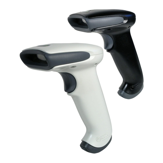
- Page 1 3800/3900 Handheld Linear Imager User’s Guide ™...
- Page 2 The information in this publication does not represent a commitment on the part of Honeywell. Honeywell shall not be liable for technical or editorial errors or omissions con- tained herein; nor for incidental or consequential damages resulting from the furnishing, performance, or use of this material.
- Page 3 The user may find the following booklet helpful: “Something About Interference.” This is available at FCC local regional offices. Honeywell is not responsible for any radio or television interfer- ence caused by unauthorized modifications of this equipment or the substitution or attachment of connecting cables and equipment other than those specified by Honeywell.
- Page 4 Nijverheidsweg 9-13 5627 BT Eindhoven The Netherlands Honeywell shall not be liable for use of our product with equipment (i.e., power supplies, personal computers, etc.) that is not CE marked and does not comply with the Low Voltage Directive. LED Safety Statement This device has been tested in accordance with IEC60825-1: 1993+A1+A2 LED safety, and has been certified to be a Class 1 LED device.
- Page 5 product disposal. Those systems will reuse or recycle most of the materials of the product you are disposing in a sound way. The crossed out wheeled bin symbol informs you that the product should not be disposed of along with municipal waste and invites you to use the appropriate separate take-back systems for product disposal.
-
Page 7: Table Of Contents
Typical Applications for the 3900 ........ 1-1 About This Manual ............1-1 Unpacking the Scanner ..........1-1 3800 Scanner Identification......... 1-2 3900 Scanner Identification......... 1-2 Connecting the Scanner with Keyboard Wedge ..1-3 Mounting Information for the 3900 ......1-4 Specular Zone ............ - Page 8 PDF417 Wand Emulation .......... 2-13 Data Block Size ........... 2-14 Delay Between Blocks ......... 2-14 Overall Checksum ..........2-15 Chapter 3 - Output Scan Rate ..............3-1 Beeper Volume ............3-1 Beeper Tone ..............3-2 Scan Voting ..............3-2 Reduce Quiet Zone............3-2 Reread Delay...............
- Page 9 Chapter 5 - Data Formatting Data Format Editor Introduction ........5-1 To Add a Data Format........... 5-1 Other Programming Selections ......5-2 Data Format Editor Commands......5-2 Data Format Editor ..........5-4 Data Formatter ............5-5 Alternate Data Formats ......... 5-5 Chapter 6 - Secondary Interface Secondary Code 39 Wand Emulation ......
- Page 10 Code 39 ............... 7-6 Start/Stop Characters..........7-6 Check Character ............ 7-6 Code 39 Message Length........7-7 Code 39 Append ............ 7-7 Code 32 Pharmaceutical (PARAF) ......7-8 Full ASCII............... 7-9 Interleaved 2 of 5 ............7-10 Check Digit ............7-10 Interleaved 2 of 5 Message Length .....
- Page 11 UPC E0 and UPC E1 ..........7-25 UPC E Expand ............ 7-25 Check Digit ............7-26 Number System........... 7-26 Addenda .............. 7-26 Addenda Required ..........7-27 Addenda Separator ..........7-27 EAN/JAN 13 .............. 7-28 Check Digit ............7-28 Addenda .............. 7-29 Addenda Required ..........
- Page 12 EAN•UCC Composite Symbology ......7-42 EAN•UCC Composite ..........7-42 Enable UPC/EAN Version ......... 7-43 EAN•UCC Composite Code Message Length ..7-43 Chapter 8 - Cloning Procedure ..............8-1 Chapter 9 - Visual Menu Visual Menu Introduction ..........9-1 Temporary Visual Menu Configuration ....9-1 Installing Visual Menu from the Web .....
- Page 13 Chapter 13 - Product Specifications 3800 Product Specifications........13-1 3900 Product Specifications........13-2 Standard Cable Pinouts ..........13-3 Chapter 14 - Maintenance Repairs ..............14-1 Maintenance.............. 14-1 Replacing the Interface Cable ......14-1 Troubleshooting ............14-2 Chapter 15 - Customer Support Technical Assistance ..........
- Page 14 viii...
-
Page 15: Chapter 1 - Getting Started
3800 marks a new performance level for handheld scanners. Linear imaging technology is defined by a bright and sharply focused aiming line, high resolu- tion imaging, and fast reading speed. The 3800 is comfortable to hold, easy to use, rugged, and excellent for all general scanning applications. -
Page 16: 3800 Scanner Identification
• Save the shipping container for later storage or shipping. 3800 Scanner Identification Compliance Label location Item Number, Serial Number and Revision Information location 3900 Scanner Identification Compliance FOR HOME OR OFFICE Tes t ed toC omplyWithF CC Sta ndar ds... -
Page 17: Connecting The Scanner With Keyboard Wedge
Connecting the Scanner with Keyboard Wedge A scanner can be connected between the keyboard and PC as a “keyboard wedge,” plugged into the serial port, or connected to a portable data terminal in wand emulation or non decoded output mode. The following is an example of a keyboard wedge connection: 1. -
Page 18: Mounting Information For The 3900
Mounting Information for the 3900 plane Aperture 1 - 4... -
Page 19: Specular Zone
Mounting Information, continued Specular Zone The 3900 must be mounted at a 5 degree, or greater, angle to the barcode in order to scan properly: The scanner is now connected and ready to communicate with your terminal/ PC. You must program the scanner for your interface before barcode data can be transmitted to your terminal/PC. - Page 20 The following Plug and Play barcode for IBM XT and Compatibles also pro- grams a carriage return (CR) suffix. IBM XT and Compatibles The following Plug and Play barcode for IBM PS-2 and Compatibles also pro- grams a carriage return (CR) suffix. IBM PS-2 and Compatibles Use Non Decoded Output Laser Emulation when connecting to a secondary terminal with integral decoding.
-
Page 21: Ibm 4683 Ports 5B, 9B, And 17 Interface
Option Setting Data Format 7 data bits, parity bit, 1 stop bit (8 bit data) RS-232 Interface In Wand Emulation mode, the scanner decodes the barcode then sends data in the same format as a wand scanner. The Same Code format transmits UPC, EAN, Code 128 and Interleaved 2 of 5 barcodes without any changes, but con- verts all other symbologies to Code 39. -
Page 22: Usb Interface
Scan one of the following “Plug and Play” codes to program the 3800 for IBM 4683 Port 5B, 9B, or 17. Note: After scanning one of these codes, you must re-boot the cash register. IBM 4683 Port 5B Interface IBM 4683 Port 9B HHBCR-1 Interface... - Page 23 Note,” available at www.honeywell.com/aidc. Scan one of the following “Plug and Play” codes to program the 3800 for IBM SurePos (USB Handheld scanner) or IBM SurePos (USB Tabletop scanner). Note: After scanning one of these codes, you must re-boot the cash register.
-
Page 24: Ocia Interface
Interleaved 2 of 5 00 0D 0B Code 128 00 18 0B Scan one of the following codes to program the 3800 for USB PC Keyboard or USB Macintosh Keyboard. USB Keyboard (PC) USB Keyboard (Mac) Scan the following code to program the 3800 for USB HID barcode scanners. -
Page 25: Ncr Ocia Short Format (8 Bit) Interface
The Generic OCIA barcode also programs the following prefixes for each sym- bology: Symbology Prefix EAN 8 06 06 EAN 13 UPC A UPC E NCR OCIA Short Format (8 Bit) Interface NCR OCIA Short Format (8 Bit) Interface The NCR OCIA Short Format (8 Bit) barcode also programs the following pre- fixes for each symbology: Symbology Prefix... -
Page 26: Nixdorf Ocia Interface
Code 128 44 4A Serial Wedge The 3800/3900 uses true and TTL signal levels to wedge into an RS-232 serial network. Use 3800/3900 serial wedge cables only to prevent damage to the scanner. Refer to the serial interface programming (pages to 2-11) to set the baud rate and communications protocol. - Page 27 * P1 Both P1 and P2 1 - 13...
- Page 28 1 - 14...
-
Page 29: Chapter 2 - Terminal Interfaces
Terminal Interfaces Keyboard Wedge Connection 3800/3900 scanners are factory programmed for a keyboard wedge interface to an IBM PC AT with a USA keyboard. If this is your interface and you do not need to modify the settings, skip to Chapter 3 - Output. -
Page 30: Supported Terminals
Supported Terminals Terminal Model(s) Terminal ID Apple Mac Mac Classic, SE SE30, II (All) 049 ** Apple Mac Powerbook 5300 Series (Portable PC) 049 ** VT510, 520, 525 (PC style) VT510, 520, 525 (DEC style LK411) Esprit 200, 400 Heath Zenith PC, AT Vectra Vectra ES... - Page 31 Supported Terminals (Continued) Terminal Model(s) Terminal ID 078, 078A, 79, 80, 191, 196, Telex 88 key 1191,1192, 1471, 1472, 1476, 1477, 1483 Telex 88 key Data Entry Keyboard 078, 078A, 79, 80, 191, 196, Telex 102 key 1191,1192, 1471, 1472, 1476, 1477, 1483 078, 078A, 79, 80, 191, 196, Telex 122 key...
-
Page 32: Keyboard Country
Keyboard Country Scan the Program Keyboard Country barcode below, then scan the numeric barcode(s) from the inside back cover, then the Save barcode to program the keyboard for your country. As a general rule, the following characters are not supported by the scanner for countries other than the United States: @ | $ # { } [ ] = / ‘... -
Page 33: Keyboard Modifiers
Shift Lock is used when you normally have the Shift Lock key on (not common to U.S. keyboards). Shift Lock Automatic Caps Lock is used if you change the Caps Lock key on and off. The software tracks and reflects if you have Caps Lock on or off (AT and PS/2 only). - Page 34 Turbo Mode: The scanner sends characters to an IBM AT terminal faster. (For use with IBM AT only.) If the terminal drops characters, do not use Turbo Mode. Default = Off Turbo Mode On * Turbo Mode Off Numeric Keypad Mode: Sends numeric characters as if entered from a numeric keypad.
-
Page 35: Serial Port Connection
Serial Port Connection All communication parameters between the scanner and terminal must match for correct data transfer through the serial port using RS-232 protocol. Scan- ning the RS-232 interface barcode, programs the scanner for an RS-232 inter- face at 9600 baud, even parity, 7 data bits, 1 stop bit (8 bit data), and adds a suffix of a CR LF. -
Page 36: Baud Rate
Baud Rate Baud Rate sends the data from the scanner to the terminal at the specified rate. The host terminal must be set for the same baud rate as the scanner. Default = 9600. 1200 2400 4800 * 9600 19200 38400 RS-232 Word Length: Data Bits, Stop Bits, and Parity Data Bits sets the word length at 7 or 8 bits of data per character. - Page 37 Parity provides a means of checking character bit patterns for validity. Default = Even. * 7 Data, 1 Stop, Parity Even 7 Data, 1 Stop, Parity None 7 Data, 1 Stop, Parity Odd 7 Data, 1 Stop, Parity Mark 7 Data, 1 Stop, Parity Space 7 Data, 2 Stop, Parity Even 7 Data, 2 Stop Parity None 7 Data, 2 Stop, Parity Odd...
- Page 38 RS-232 Word Length: Data Bits, Stop Bits, and Parity (continued) 7 Data, 2 Stop, Parity Space 8 Data, 1 Stop, Parity Even 8 Data, 1 Stop, Parity None 8 Data, 1 Stop, Parity Odd 8 Data, 1 Stop, Parity Mark 8 Data, 1 Stop, Parity Space 2 - 10...
-
Page 39: Rs-232 Handshaking
RS-232 Handshaking RS-232 handshaking is a set of rules concerning the exchange of data between serially communicating devices. Default = RTS/CTS, XON/XOFF and ACK/ NAK Off RTS/CTS On * RTS/CTS Off XON/XOFF On * XON/OFF Off ACK/NAK On * ACK/NAK Off Wand Emulation Connection In Wand Emulation mode, the scanner decodes the barcode then sends data in the same format as a wand scanner. -
Page 40: Wand Emulation Transmission Rate
Interleaved 2 of 5 without any changes, but converts all other symbologies to Code 39. These codes set the transmission rate to 25 inches per second and the output polarity to black, high. Default = Code 39 Format. * Code 39 Format Same Code Format Note: For the 3800PDF model: When the 3800PDF interface is set to wand emulation, all PDF417 barcode data is transmitted as Code 128. -
Page 41: Wand Emulation Polarity
Wand Emulation Polarity The Polarity can be sent as standard with black bars high, or reversed with white bars high. Default = Black High. * Black High White High Wand Emulation Idle The idle describes the state of the scanner when no data is being transmitted. When in Wand Emulation mode, you must set the scanner’s idle state to match the idle state for the device to which the scanner is connected. -
Page 42: Data Block Size
Data Block Size This transmits the PDF417 data in smaller blocks to prevent buffer overflow. Default = 60. * 60 Delay Between Blocks This sets the delay time between data blocks. Default = 50ms. * 50ms 150ms 500ms 2 - 14... -
Page 43: Overall Checksum
Overall Checksum When this option is turned on, a computed check character is added at the end of the entire message. The check character is the character which when Exclu- sive-OR’d with every preceding character of the message yields a result of 0x00 (00H). - Page 44 2 - 16...
-
Page 45: Chapter 3 - Output
Output Scan Rate Adjusting the scan rate changes the current draw when scanning. The slower the scan rate, the lower the current draw. (The standby current remains the same.) Scan speeds are 270 s/s, 135 s/s, and 67 s/s. A scan speed of 270 draws the highest power and has the best performance. -
Page 46: Beeper Tone
Beeper Tone Default = Normal. * Normal Beep Short Beep Scan Voting This sets the number of times the same barcode has to be read before it is transmitted to the terminal. Normal uses the default values listed for the sym- bologies in the Default Charts beginning on page 12-5. -
Page 47: Reread Delay
Reread Delay This sets the time period before the scanner can read the same barcode a sec- ond time. Setting a reread delay protects against accidental rereads of the same barcode. Longer delays are effective in minimizing accidental rereads at POS (point of sale). -
Page 48: Good Read Delay
(see Serial Trigger Time Out, which follows). Default for 3800. Manual/Serial Trigger Serial Trigger Time Out: Use this selection to set a time out (in quarter sec- onds) of the scanner’s trigger when using serial commands to trigger the scan- ner. - Page 49 or manually. After scanning the Serial Trigger Time Out barcode, set the time out duration (from 0-1200 quarter seconds) by scanning digits from the inside back cover, then scanning Save. Default = 0 (infinite, or no time out). Serial Trigger Time Out Manual Trigger, Low Power: The scanner “sleeps,”...
- Page 50 Mode uses normal office or store ambient light to detect the barcodes. Presentation Mode Note: Do not use Presentation Mode with a 3800/3900PDF. Normal office or store ambient light does not provide enough illumination for the 3800/ 3900PDF to work properly in Presentation Mode.
-
Page 51: Chapter 4 - Data Editing
Data Editing Prefix/Suffix Overview When a barcode is scanned, additional information is sent to the host computer along with the barcode data. This group of barcode data and additional, user-defined data is called a “message string.” The selections in this section are used to build the user-defined data into the message string. -
Page 52: To Clear One Or All Prefixes Or Suffixes
Step 4. Determine the hex value from the Decimal to Hex to ASCII Conversion Chart (page 4-5) for the prefix or suffix you wish to enter. Step 5. Scan the 2 digit hex value from the Programming Chart inside the back cover. -
Page 53: To Add A Carriage Return Suffix To All Symbologies
To Add a Carriage Return Suffix to all Symbologies Scan the following barcode if you wish to add a Carriage Return Suffix to all symbologies at once. This action first clears all current suffixes, then programs a carriage return suffix for all symbologies. Add CR Suffix All Symbologies Prefix Selections... -
Page 54: Symbology Chart
Symbology Chart Code Code Symbology Symbology China Post Matrix 2 of 5 Codabar MicroPDF417 Code 11 Code 32 Pharmaceutical PDF417 (PARAF) Code 39 Plessey Code Straight 2 of 5 Code 93 IATA Straight 2 of 5 Code 128 Industrial EAN/JAN Telepen •... -
Page 55: Ascii Conversion Chart (Code
ASCII Conversion Chart (Code Page 1252 Note: This table applies to U.S. style keyboards. Certain characters may differ depending on your Country Code/PC regional settings. Dec Hex Char Hex Char Dec Char Dec Hex Char ‘ “ & ‘ < >... -
Page 56: Function Code Transmit
Function Code Transmit When this selection is enabled and function codes are contained within the scanned data, the scanner transmits the function code to the terminal. Charts of these function codes are provided in Section 10, Supported Interface Keys. When the scanner is in keyboard wedge mode, the scan code is converted to a key code before it is transmitted. -
Page 57: Intercharacter Delay
Intercharacter Delay This is a delay of up to 495 milliseconds (in multiples of 5) placed between the transmission of each character of scanned data. You can program up to 99 steps (of 5 ms each). Scan the Intercharacter Delay barcode below, then scan the number of steps, and the SAVE barcode from the inside back cover. -
Page 58: Interfunction Delay
To remove this delay, scan the Delay Length barcode, and set the number of steps to 00. Scan the SAVE barcode from the inside back cover. Interfunction Delay This is a delay of up to 495 milliseconds (in multiples of 5) placed between the transmission of each segment of the message string. -
Page 59: Chapter 5 - Data Formatting
Data Formatting Data Format Editor Introduction The Data Format Editor selections are used to edit scanned data. For example, you can use the Data Format Editor to insert characters at certain points in bar- code data as it is scanned. It is not necessary to use the Data Format Editor. A set of defaults for the data format is already programmed in the scanner. -
Page 60: Other Programming Selections
Step 4. Code I.D. page 4-4, find the symbology to which you want to apply the data format. Locate the Hex value for that symbology and scan the 2 digit hex value from the Programming Chart. Step 5. Length Specify what length (up to 9999 characters) of data will be acceptable for this symbology. - Page 61 E9 Send all but the last “nn” characters, starting from the current cursor posi- tion. Syntax = E9nn (nn is the numeric value (00-99) for the number of characters that will not be sent at the end of the message.) Move Commands F5 Move the cursor ahead “nn”...
-
Page 62: Data Format Editor
FE Compare character in current cursor position to the character “xx.” If char- acters are equal, increment cursor. If characters are not equal, no format match. Syntax = FExx (xx stands for the hex value for an ASCII code, see Decimal to Hex to ASCII Conversion chart, page 4-5.) -
Page 63: Data Formatter
Data Formatter When Data Formatter is turned off, the barcode data is output to the host as read (including prefixes and suffixes). Choose one of the following options. Default = Data Formatter On. * Data Formatter On, but Not Required Data Formatter Off When Data Formatter is required, all input data must conform to an edited for- mat or the scanner does not transmit the input data to the host device. - Page 64 5 - 6...
-
Page 65: Chapter 6 - Secondary Interface
Secondary Interface By switching interface cables, the 3800/3900 scanner can communicate with a portable data terminal (secondary interface), in addition to the host terminal (primary interface). Note: Secondary interfaces do not apply to the 3800XX-15. The secondary interface can be programmed at any time. -
Page 66: Secondary Non Decoded Output Laser Emulation
Secondary Non Decoded Output Laser Emulation Use this selection when connecting to a secondary terminal with integral decod- ing. This also sets the transmission rate to 36 scans per second and the polar- ity to white high. Non Decoded Output Non Decoded Output Laser Emulation Transmission Rate The Transmission Rate is limited by the terminal’s ability to receive data without... -
Page 67: Non Decoded Laser Emulation Idle
Non Decoded Laser Emulation Idle The idle describes the state of the scanner when no data is being transmitted. When in Non Decoded mode, you must set the scanner’s idle state to match the idle state for the device to which the scanner is connected. Default = High. * High Disabling the Secondary Interface You can temporarily disable the secondary interface, but still retain the second-... - Page 68 Automatic Trigger: The scanner scans continuously at full power. Automatic Trigger Manual Trigger, Low Power: The scanner “sleeps,” using only 30 milliamps, until the trigger is pulled. When the trigger is pulled, the scanner wakes up and operates at normal power until there is no triggering for the time set with the Low Power Time Out barcode.
-
Page 69: Introduction
Symbologies Introduction Use this section to program the scanner for Industrial, Retail, and PDF417 Sym- bology selections. This programming section contains the following menu selections: • All Symbologies • Interleaved 2 of 5 • China Post Code • Matrix 2 of 5 •... -
Page 70: Message Length Description
Message Length Description You are able to set the valid reading length of some of the barcode symbologies. If the data length of the scanned barcode doesn’t match the valid reading length, the imager will issue an error beep. You may wish to set the same value for minimum and maximum length to force the imager to read fixed length barcode data. -
Page 71: Codabar
Codabar <Default All Codabar Settings> Codabar * On Start/Stop Characters Start/Stop characters identify the leading and trailing ends of the barcode. You may either transmit, or not transmit Start/Stop characters. Default = Don’t Transmit . Transmit * Don’t Transmit Check Character Codabar check characters are created using different “modulos.”... -
Page 72: Concatenation
When Check Character is set to Validate, but Don’t Transmit , the unit will only read Codabar barcodes printed with a check character, but will not transmit the check character with the scanned data. * No Check Character Validate Modulo 16, but Don’t Transmit Validate Modulo 16 and Transmit Concatenation... -
Page 73: Codabar Message Length
Codabar Message Length Scan the barcodes below to change the message length. Refer to Message Length Description (page 7-2) for additional information. Minimum and Maximum lengths = 2-60. Minimum Default = 4, Maximum Default = 60. Minimum Message Length Maximum Message Length 7 - 5... -
Page 74: Start/Stop Characters
Code 39 < Default All Code 39 Settings > Code 39 * On Start/Stop Characters Start/Stop characters identify the leading and trailing ends of the barcode. You may either transmit, or not transmit Start/Stop characters. Default = Don’t Transmit. Transmit * Don’t Transmit Check Character No Check Character indicates that the scanner reads and transmits barcode... -
Page 75: Code 39 Message Length
When Check Character is set to Validate and Transmit, the scanner will only read Code 39 barcodes printed with a check character, and will transmit this character at the end of the scanned data. Default = No Check Character. * No Check Character Validate, but Don’t Transmit Validate and Transmit Code 39 Message Length... -
Page 76: Code 32 Pharmaceutical (Paraf)
are read, deleting the first space from each. The scanner transmits the appended data when it reads a Code 39 barcode that starts with a character other than a space. Default = Off. * Off Code 32 Pharmaceutical (PARAF) Code 32 Pharmaceutical (PARAF) is a form of the Code 39 symbology used by Italian pharmacies. -
Page 77: Full Ascii
Full ASCII If Full ASCII Code 39 decoding is enabled, certain character pairs within the barcode symbol will be interpreted as a single character. For example: $V will be decoded as the ASCII character SYN, and /C will be decoded as the ASCII character #. -
Page 78: Interleaved 2 Of 5
Interleaved 2 of 5 < Default All Interleaved 2 of 5 Settings > Interleaved 2 of 5 * On Check Digit No Check Digit indicates that the scanner reads and transmits barcode data with or without a check digit. When Check Digit is set to Validate, but Don’t Transmit, the unit will only read Interleaved 2 of 5 barcodes printed with a check digit, but will not transmit the check digit with the scanned data. -
Page 79: Interleaved 2 Of 5 Message Length
Interleaved 2 of 5 Message Length Note: Scan the barcodes below to change the message length. Refer to Message Length Description (page 7-2) for additional information. Minimum and Maximum lengths = 2-80. Minimum Default = 4, Maximum Default = 80 . Minimum Message Length Maximum Message Length Strict Decoding... -
Page 80: Code 93
Code 93 < Default All Code 93 Settings > Code 93 * On Code 93 Message Length Note: Scan the barcodes below to change the message length. Refer to (page 7-2) for additional information. Message Length Description Minimum and Maximum lengths = 0-80. Minimum Default = 0, Maximum Default = 80 . -
Page 81: Straight 2 Of 5 Industrial
Straight 2 of 5 Industrial <Default All Straight 2 of 5 Industrial Settings> Straight 2 of 5 Industrial * On Straight 2 of 5 Industrial Message Length Note: Scan the barcodes below to change the message length. Refer to (page 7-2) for additional information. Message Length Description Minimum and Maximum lengths = 1-48. -
Page 82: Straight 2 Of 5 Iata
Straight 2 of 5 IATA <Default All Straight 2 of 5 IATA Settings> Straight 2 of 5 IATA * On Straight 2 of 5 IATA Message Length Note: Scan the barcodes below to change the message length. Refer to (page 7-2) for additional information. Message Length Description Minimum and Maximum lengths = 1-48. -
Page 83: Matrix 2 Of 5
Matrix 2 of 5 <Default All Matrix 2 of 5 Settings> Matrix 2 of 5 * On Matrix 2 of 5 Message Length Note: Scan the barcodes below to change the message length. Refer to Message Length Description (page 7-2) for additional information. Minimum and Maximum lengths = 1-80. -
Page 84: Code 11
Code 11 <Default All Code 11 Settings> Code 11 * On Check Digits Required This option sets whether 1 or 2 check digits are required with Code 11 bar- codes. Default = Two Check Digits. One Check Digit * Two Check Digits 7 - 16... -
Page 85: Code 11 Message Length
Code 11 Message Length Note: Scan the barcodes below to change the message length. Refer to Message Length Description (page 7-2) for additional information. Minimum and Maximum lengths = 1-80. Minimum Default = 4, Maximum Default = 80 . Minimum Message Length Maximum Message Length 7 - 17... -
Page 86: Code 128
Code 128 <Default All Code 128 Settings> Code 128 * On <GS> Substitution When enabled, the scanner substitutes a <GS> for Function Character 1 when decoding EAN 128. Default =Off. * Off 7 - 18... -
Page 87: Code 128 Message Length
Code 128 Message Length Note: Scan the barcodes below to change the message length. Refer to Message Length Description (page 7-2) for additional information. Minimum and Maximum lengths = 0-80. Minimum Default = 0, Maximum Default = 80 . Minimum Message Length Maximum Message Length 7 - 19... -
Page 88: Telepen
Telepen <Default All Telepen Settings> Telepen * On Telepen Output Using AIM Telepen Output, the scanner reads symbols with start/stop pattern 1 and decodes them as standard full ASCII (start/stop pattern 1). When Original Telepen Output is selected, the scanner reads symbols with start/stop pattern 1 and decodes them as compressed numeric with optional full ASCII (start/stop pattern 2). -
Page 89: Telepen Message Length
Telepen Message Length Note: Scan the barcodes below to change the message length. Refer to Message Length Description (page 7-2) for additional information. Minimum and Maximum lengths = 1-60. Minimum Default = 1, Maximum Default = 60 . Minimum Message Length Maximum Message Length 7 - 21... -
Page 90: Upc A
UPC A <Default All UPC A Settings> UPC A * On Check Digit This selection allows you to specify whether the check digit should be transmit- ted at the end of the scanned data or not. Default = On. * On Number System The numeric system digit of a UPC symbol is normally transmitted, but the unit can be programmed so it will not transmit it. -
Page 91: Addenda
Addenda This selection adds 2 or 5 digits to the end of all scanned UPC A data. Default = Off for both 2 Digit and 5 Digit Addenda. 2 Digit Addenda On * 2 Digit Addenda Off 5 Digit Addenda On * 5 Digit Addenda Off Addenda Required When Addenda Required is set to on, the scanner will only read UPC A bar-... -
Page 92: Addenda Separator
Addenda Separator When this feature is on, there is a space between the data from the barcode and the data from the addenda. When turned off, there is no space. Default = On. * On UPC Strict Decoding When UPC Strict Decoding is used, the scanner only reads barcodes that are close to spec. -
Page 93: Upc E0 And Upc E1
UPC E <Default All UPC E Settings> UPC E0 and UPC E1 Most UPC barcodes lead with the 0 number system. For these codes, use the UPC E0 selection. If you need to read codes that lead with the 1 number sys- tem, use the UPC E1 selection. -
Page 94: Check Digit
Check Digit Check Digit specifies whether the check digit should be transmitted at the end of the scanned data or not. Default = On. * On Number System The numeric system digit of a UPC symbol is normally transmitted, but the unit can be programmed so it will not transmit it. -
Page 95: Addenda Required
Addenda Required When Addenda Required is set to on, the scanner will only read UPC E bar- codes that have addenda. Default = Off. Required * Not Required Addenda Separator When this feature is on, there is a space between the data from the barcode and the data from the addenda. -
Page 96: Ean/Jan 13
EAN/JAN 13 <Default All EAN/JAN Settings> EAN/JAN 13 * On Check Digit This selection allows you to specify whether the check digit should be transmit- ted at the end of the scanned data or not. Default = On. * On 7 - 28... -
Page 97: Addenda
Addenda This selection adds 2 or 5 digits to the end of all scanned EAN/JAN 13 data. Default = Off for both 2 Digit and 5 Digit Addenda. 2 Digit Addenda On * 2 Digit Addenda Off 5 Digit Addenda On * 5 Digit Addenda Off Addenda Required When Addenda Required is set to on, the scanner will only read EAN/JAN 13... -
Page 98: Addenda Separator
Addenda Separator When this feature is on, there is a space between the data from the barcode and the data from the addenda. When turned off, there is no space. Default = On. * On ISBN Enable This symbology allows the scanner to read ISBN codes on books. Default = Off. * Off 7 - 30... -
Page 99: Ean/Jan 8
EAN/JAN 8 <Default All EAN/JAN 8 Settings> EAN/JAN 8 * On Check Digit This selection allows you to specify whether the check digit should be transmit- ted at the end of the scanned data or not. Default = On. * On 7 - 31... -
Page 100: Addenda
Addenda This selection adds 2 or 5 digits to the end of all scanned EAN/JAN 8 data. Default = Off for both 2 Digit and 5 Digit Addenda. 2 Digit Addenda On * 2 Digit Addenda Off 5 Digit Addenda On * 5 Digit Addenda Off Addenda Required When Addenda Required is set to on, the scanner will only read EAN/JAN 8... -
Page 101: Msi
<Default All MSI Settings> * Off Check Character Different types of check characters are used with MSI barcodes. You can program the scanner to read only MSI barcodes with Type 10 or Type 11 check characters. Default = Validate Type 10, but Don’t Transmit. When Check Character is set to Validate and Transmit , the scanner will only read MSI barcodes printed with the specified type check character, and will transmit this character at the end of the scanned data. -
Page 102: Msi Message Length
When Check Character is set to Validate, but Don’t Transmit , the unit will only read MSI barcodes printed with the specified type check character, but will not transmit the check character with the scanned data. * Validate Type 10, but Don’t Transmit Validate Type 10 and Transmit Validate Type 11, but Don’t... -
Page 103: Plessey
Plessey <Default All Plessey Settings> Plessey * Off Plessey Message Length Note: Scan the barcodes below to change the message length. Refer to (page 7-2) for additional information. Message Length Description Minimum and Maximum lengths = 4-48. Minimum Default = 4, Maximum Default = 48 . -
Page 104: Gs1 Databar
GS1 DataBar < Default All GS1 DataBar Settings > GS1 DataBar GS1 DataBar is a family of linear barcodes that meets restricted space require- ments, while still providing full product identification. * Off GS1 DataBar Limited < Default All GS1 DataBar Limited Settings > GS1 DataBar Limited * Off 7 - 36... -
Page 105: Gs1 Databar Expanded
GS1 DataBar Expanded < Default All GS1 DataBar Expanded Settings > GS1 DataBar Expanded * Off GS1 DataBar Expanded Message Length Note: Scan the barcodes below to change the message length. Refer to Message Length Description (page 7-2) for additional information. Minimum and Maximum lengths = 4-74. -
Page 106: China Post Code
China Post Code <Default All China Post Code Settings> China Post Code * Off China Post Message Length Note: Scan the barcodes below to change the message length. Refer to (page 7-2) for additional information. Message Length Description Minimum and Maximum lengths = 2-80. Minimum Default = 4, Maximum Default = 80 . -
Page 107: Pdf417
PDF417 Note: The following selections are for use with the 3800/3900PDF-12 and 3800/ 3900PDF-12E scanners only. <Default All PDF417 Settings> PDF417 * On PDF417 Message Length Note: Scan the barcodes below to change the message length. Refer to (page 7-2) for additional information. -
Page 108: Show Gli Blocks
Show GLI Blocks Turning Show GLI Blocks On causes GLI commands to be issued where located within their encoded data sequences. When on, the “\” is used as an escape character and natural occurrences of “\” in data are replaced by “\\”. Default = Off . -
Page 109: Pdf Learn Mode
Because some PDF417 codes are more compact than others, the reading distance varies from code to code. When you turn on the PDF Learn Mode, the 3800/3900’s light becomes very bright when you are at the best distance for reading the PDF417 code. Default = Off. -
Page 110: Micropdf417 Message Length
= 1-366. Minimum Default = 1, Maximum Default = 366. Minimum Message Length Maximum Message Length UCC Composite Symbology • Note: The following selections are for use with the 3800/3900PDF-12 and 3800/ 3900PDF-12E scanners only. < Default All EAN UCC Composite Symbology Settings > •... -
Page 111: Enable Upc/Ean Version
Enable UPC/EAN Version Turn on this selection to decode EAN•UCC composite symbols having a UPC or EAN primary component. *Off EAN•UCC Composite Code Message Length Scan the barcodes below to change the message length. Refer to Message (page 7-2) for additional information. Minimum and Length Description Maximum lengths = 1-2435. - Page 112 7 - 44...
-
Page 113: Chapter 8 - Cloning
“source” scanner. Before using this procedure, determine which scanner will be the source (the scanner containing the desired software). The 3800/3900 supports cloning and can act as the source device. The software in the destination scanner will be updated from the source scan- ner. - Page 114 8 - 2...
-
Page 115: Chapter 9 - Visual Menu
Visual Menu Installing Visual Menu from the Web 1. Access the Honeywell web site at www.honeywell.com/aidc. 2. Click in the Resources tab, then on Product Downloads - Software. 3. Click on the dropdown box for Select Product Number and select 3900. -
Page 116: Upgrading Usb Firmware
4. Click on the entry for Visual Menu. 5. When prompted, select Save File, and save the files to the c:\windows\temp directory. 6. Once you have finished downloading the file, exit the web site. 7. Using Explorer, go to the c:\windows\temp file and unzip the file you saved. 8. -
Page 117: Chapter 10 - Interface Keys
Interface Keys Keyboard Function Relationships The following Keyboard Function Code, Hex/ASCII Value, and Full ASCII “CTRL”+ relationships apply to all terminals that can be used with the scanner. Function Code HEX/ASCII Value Full ASCII “CTRL” + 10 - 1... - Page 118 The last five characters in the Full ASCII “CTRL”+ column ( [ \ ] 6 - ), apply to US only. The following chart indicates the equivalents of these five characters for different countries. Country Codes United States Belgium < Scandinavia <...
-
Page 119: Supported Interface Keys
Supported Interface Keys IBM AT/XT and Supported PS/2 Compatibles, IBM XTs and IBM, DDC, Memorex Interface Keys WYSE PC/AT Compatibles Telex, Harris* Reserved Reserved Reserved Enter (KP) CR/Enter Enter Cap Lock Caps Lock ALT make Reserved ALT break Reserved CTRL make Reserved CTRL break Reserved... - Page 120 Supported Interface Keys Supported Interface Keys IBM, Memorex Telex (102)* Memorex Telex (88)** Reserved Reserved Enter Enter PF10 PF11 PF12 Reserved Reserved New Line New Line Field Forward Field Forward Reserved Tab/Field Forward Field Forward Delete Delete Field Exit New Line Insert Insert Clear...
-
Page 121: Supported Interface Keys
Supported Interface Keys Supported Esprit 200, 400 Esprit 200, 400 Esprit 200, 400 Interface Keys ANSI ASCII Reserved Reserved Reserved New Line New Line New Line New Line New Line New Line Delete New Line New Line New Line Insert Escape Escape Escape... - Page 122 Supported Interface Keys Supported Interface Keys Apple Mac/iMac Reserved Enter/Numpad Enter CAPS ALT make ALT break CNTRL make CNTRL break RETURN APPLE make APPLE break RETURN Ins Help Home Prnt Scrn BACKSPACE LSHIFT TAB BACKSPACE 10 - 6...
-
Page 123: Chapter 11 - Utilities
Utilities To Add a Test Code I.D. Prefix to All Symbologies This selection allows you to turn on transmission of a Code I.D. before the decoded symbology. (See the Symbology Chart on page 4-4 for the single character code that identifies each symbology.) This action first clears all cur- rent prefixes, then programs a Code I.D. -
Page 124: Specular Effect Reduction
Specular Effect Reduction When the On code is scanned, the first pass read rate and voting threshold are increased. Default = Off. * Off Note: If you want to further limit specular effects, reduce the scan speed using "Scan Rate" on page 3-1. 11 - 2... -
Page 125: Chapter 12 - Serial Programming Commands
The serial programming commands can be used in place of the programming barcodes. Both the serial commands and the programming barcodes will pro- gram the 3800/3900. For complete descriptions and examples of each serial programming command, refer to the corresponding programming barcode in this manual. -
Page 126: Query Commands
Query Commands Several special characters can be used to query the device about its settings. What is the default value for the setting(s). What is the device’s current value for the setting(s). What is the range of possible values for the setting(s). (The de- vice’s response uses a dash (-) to indicate a continuous range of values. - Page 127 Examples of Query Commands In the following examples, a bracketed notation [ ] depicts a non-displayable response. Example #1:What is the range of possible values for Codabar Coding Enable? Enter: cbrena*. Response: CBRENA0-1[ACK] This response indicates that Codabar Coding Enable (CBRENA) has a range of values from 0 to 1 (off and on).
-
Page 128: Trigger Commands
Trigger Commands You can activate and deactivate the scanner with serial trigger commands. First, the scanner must be put in Manual/Serial Trigger Mode either by scanning the Manual/Serial Trigger Mode barcode (page 3-4), or by sending the Manual/ Serial Menu Command (page 12-8). -
Page 129: Menu Commands
Menu Commands Serial Setting Command Selection Page * Indicates default # Indicates a numeric entry Factory Default Settings Default DEFALT Terminal Interfaces Terminal ID *003 (default for model -12) TERMID### *000 (default for model -13) *124 (default for models 14- Program Keyboard KBDCTY Country... - Page 130 Serial Setting Command Selection Page * Indicates default # Indicates a numeric entry Word Length: Data Bits, *7 Data, 1 Stop, Parity Even 232WRD3 Stop Bits, and Parity 7 Data, 1 Stop, Parity None 232WRD0 7 Data, 1 Stop, Parity Odd 232WRD6 7 Data, 1 Stop, Parity Mark 232WRD12...
-
Page 131: Pdf417 Wand Emulation
Serial Setting Command Selection Page * Indicates default # Indicates a numeric entry Wand Emulation Idle Idle Low WNDIDL0 2-13 *Idle High WNDIDL1 2-13 PDF417 Wand Emulation Data Block Size WNDBLK0 2-14 WNDBLK1 2-14 WNDBLK2 2-14 WNDBLK3 2-14 Delay Between Blocks WNDDLY0 2-14 *50ms... -
Page 132: Data Formatter Selections
GRDDLY0 Short Delay GRDDLY1 Medium Delay GRDDLY2 Long Delay GRDDLY3 Trigger Mode *Manual/Serial Trigger TRGMOD0 (default for 3800) Serial Trigger Time Out *0 TRGSTO#### Low Power Time Out TRGLPT### *Automatic Trigger (default TRGMOD1 for 3900) Manual Trigger, Low Power TRGMOD2... - Page 133 Serial Setting Command Selection Page * Indicates default # Indicates a numeric entry Data Formatter DFM_EN0 *On, but Not Required DFM_EN1 On, Required DFM_EN2 Alternate Data Formats VSAF_1 VSAF_2 VSAF_3 Secondary Interface Selections Wand Emulation Same Code Format 2IFTYP0 Connection *Code 39 Format 2IFTYP1 Secondary RS-232...
- Page 134 Serial Setting Command Selection Page * Indicates default # Indicates a numeric entry Codabar Start/Stop Char. *Don’t Transmit CBRSSX0 Transmit CBRSSX1 Codabar Check Char. *No Check Char. CBRCK20 Validate Modulo 16, But CBRCK23 Don’t Transmit Validate Modulo 16, and CBRCK24 Transmit Codabar Concatenation CBRCCT0...
- Page 135 Serial Setting Command Selection Page * Indicates default # Indicates a numeric entry Interleaved 2 of 5 Check *No Check Char. I25CK20 7-10 Digit Validate, But Don’t I25CK21 7-10 Transmit Validate, and Transmit I25CK22 7-10 Interleaved 2 of 5 Minimum (2-80) *4 I25MIN## 7-11 Message Length...
- Page 136 Serial Setting Command Selection Page * Indicates default # Indicates a numeric entry Code 11 C11ENA0 7-16 C11ENA1 7-16 Code 11 Check Digits 1 Check Digit C11CK20 7-16 Required *2 Check Digits C11CK21 7-16 Code 11 Message Length Minimum (1 - 80) *4 C11MIN## 7-17 Maximum (1 - 80) *80...
- Page 137 Serial Setting Command Selection Page * Indicates default # Indicates a numeric entry UPC A Addenda *Off UPAARQ0 7-23 Required UPAARQ1 7-23 UPC A Addenda UPAADS0 7-24 Separator UPAADS1 7-24 UPC Strict Decoding *Off UPCSTR0 7-24 UPCSTR1 7-24 UPC E Default All UPC E UPEDFT 7-25...
- Page 138 Serial Setting Command Selection Page * Indicates default # Indicates a numeric entry EAN/JAN 13 5 Digit *Off E13AD50 7-29 Addenda E13AD51 7-29 EAN/JAN 13 Addenda *Off E13ARQ0 7-29 Required E13ARQ1 7-29 EAN/JAN 13 Addenda E13ADS0 7-30 Separator E13ADS1 7-30 ISBN Enable *Off E13ISB0...
- Page 139 Serial Setting Command Selection Page * Indicates default # Indicates a numeric entry MSI Message Length Minimum (4 - 48) *4 MSIMIN## 7-33 Maximum (4 - 48) *48 MSIMAX## 7-33 Plessey Default All Plessey Settings PLSDFT 7-35 Plessey *Off PLSENA0 7-35 PLSENA1 7-35...
- Page 140 Serial Setting Command Selection Page * Indicates default # Indicates a numeric entry Scan Diagnostics *Off PDFDIA0 7-40 PDFDIA1 7-40 PDF Learn Mode *Off PDFLRN0 7-41 PDFLRN1 7-41 MicroPDF417 Default All MicroPDF417 MPDDFT 7-41 Settings MicroPDF417 *Off MPDENA0 7-41 MPDENA1 7-41 MicroPDF417 Message Minimum (1-366) *1...
-
Page 141: Chapter 13 - Product Specifications
Product Specifications 3800 Product Specifications Parameter Specification Dimensions: Height 6.0 inches (15.2 cm) Length 5.3 inches (13.5 cm) Weight 6.3 ounces ( 179.2 g) Width 3.1 inches ( 7.9 cm) Light Source 630 nm visible red LED Scan Rate Programmable to 270 scans per second ±30 degrees... -
Page 142: 3900 Product Specifications
3900 Product Specifications Parameter Specification Dimensions: Height 1.5 inches (3.8 cm) Length 4.7 inches (11.9 cm) Width 3.1 inches ( 7.9 cm) Light Source 630 nm visible red LED Scan Rate Programmable to 270 scans per second ±30 degrees Skew Angle ±15 degrees Pitch Angle Horizontal Velocity... -
Page 143: Standard Cable Pinouts
Standard Cable Pinouts Laser Output Only (Laser Compatible Bar Image) 13 - 3... - Page 144 Standard Cable Pinouts Keyboard Wedge 13 - 4...
- Page 145 Standard Cable Pinouts Wand Emulation 13 - 5...
- Page 146 Standard Cable Pinouts (Primary Interface Cables) Serial Output 13 - 6...
- Page 147 Standard Cable Pinouts 13 - 7...
- Page 148 13 - 8...
-
Page 149: Chapter 14 - Maintenance
See "Customer Support" on page 15-1 for further information. Maintenance The 3800/3900 provides reliable and efficient operation with a minimum of care. Although specific maintenance is not required, the following periodic checks ensure dependable scanner operation: Cleaning the Scanner’s Window... -
Page 150: Troubleshooting
• Order replacement cables from Honeywell or from an authorized distributor. • When ordering a replacement cable, specify the cable part number of the original interface cable. To Replace the Interface Cable: 1. Turn the power to the host system OFF. - Page 151 2. Aren’t coated with frost or water droplets on the surface. 3. Are enabled in the scanner or in the decoder to which the scanner connects. Is the barcode displayed but not entered? The barcode is displayed on the host device correctly, but you still have to press a key to enter it (the Enter/Return key or the Tab key, for example).
- Page 152 14 - 4...
-
Page 153: Chapter 15 - Customer Support
Telephone - Hong Kong: +852-3188-3485 or 2511-3050 Telephone - China: +86 21 6361 3818 E-mail: aptechsupport@honeywell.com Japan Telephone: +813 5770-6312 E-mail: aptechsupport@honeywell.com Malaysia Telephone: +603-6201-7020 E-mail: aptechsupport@honeywell.com Online Technical Assistance You can also access technical assistance online at www.honeywell.com/aidc. 15 - 1... -
Page 154: Product Service And Repair
Product Service and Repair Honeywell provides service for all its products through service centers through- out the world. To obtain warranty or non-warranty service, contact the appropri- ate location below to obtain a Return Material Authorization number (RMA #) before returning the product. - Page 155 Honeywell or its authorized representatives. This warranty shall extend from the time of shipment for the duration published by Honeywell for the product at the time of purchase ("Warranty Period"). Any defective product must be returned (at purchaser’s expense) during the War- ranty Period to Honeywell’s factory or authorized service center for inspection.
- Page 156 This includes but is not limited to: cables, power supplies, cra- dles, and docking stations. Honeywell extends these warranties only to users of the products. These warranties are non-transferable. The duration of the limited warranty for the 3800/3900 is for five (5) years. 15 - 4...
- Page 160 Sample Symbols UPC A Interleaved 2 of 5 0 123456 7890 1234567890 Code 128 Code 128 EAN 13 9 780330 290951 Code 39 BC321 Codabar A13579B...
- Page 161 Sample Symbols PDF417 MicroPDF417 PDF417 Test Message MicroPDF417 Test Message Code 93 Code 2 of 5 123456-9$ Matrix 2 of 5 123456 6543210 GS1 DataBar (01)00123456789012 UCC Composite • Symbology with GS1 DataBar Limited (01)12345678901231(10)123456789(11)001205(3202)001234...
- Page 162 Programming Chart...
- Page 163 Programming Chart Save Discard...
- Page 164 Honeywell 700 Visions Drive P.O. Box 208 Skaneateles Falls, NY 13153-0208 38-3900-DO-UG Rev H 11/08...