Table of Contents
Advertisement
HD CAMERA RECORDER
GY-HD110
GY-HD111
Thank you for purchasing this JVC product. Before operating this
unit, please read the instructions carefully to ensure the best
possible performance.
For Customer Use :
Enter below the Serial No. which is located on the body.
Retain this information for future reference.
Model No.
Serial No.
INSTRUCTIONS
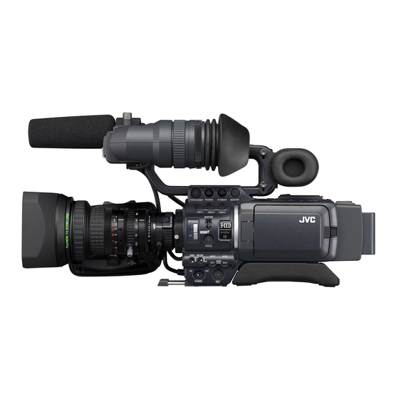
* The illustration shows the GY-HD110/GY-
HD111 HD CAMERA RECORDER with the pro-
vided lens, viewfinder, microphone and battery
pack attached.
E
INTRODUCTION
CONTROLS,
INDICATORS AND
CONNECTORS
PREPARATIONS
PREPARATIONS
FOR OPERATION
SETTING AND
ADJUSTMENTS
BEFORE SHOOTING
SHOOTING
OPERATION
PLAYBACK MODE
USING EXTERNAL
COMPONENTS
MENU SCREENS
FEATURES OF THE
CAMERA SECTION
OTHERS
LST0392-001B
Advertisement
Table of Contents

Related Manuals for JVC GY-HD110


Summary of Contents for JVC GY-HD110
- Page 1 OTHERS * The illustration shows the GY-HD110/GY- HD111 HD CAMERA RECORDER with the pro- Thank you for purchasing this JVC product. Before operating this vided lens, viewfinder, microphone and battery unit, please read the instructions carefully to ensure the best pack attached.
- Page 3 Important Safety Instructions Read all of these instructions. Keep these instructions. Heed all warnings. Follow all instructions. Do not use this apparatus near water. Clean only with dry cloth. Do not block any ventilation openings. Install in accordance with the manufacturer’s instructions. Do not install near any heat sources such as radiators, heat resisters, stoves, or other apparatus (includ- ing amplifiers) that produce heat.
- Page 4 Consult the dealer or an experienced radio/TV technician for help. CAUTION: CHANGES OR MODIFICATIONS NOT APPROVED BY JVC COULD VOID USER’S AUTHORITY TO OPERATE THE EQUIPMENT. THIS DEVICE COMPLIES WITH PART 15 OF THE FCC RULES.
-
Page 5: Caution For Ac Mains Lead
If the plug supplied is not suitable for your socket outlet, it should electrical safety. be cut off and appropriate one fitted. European representative of Victor Company of Japan Limited is: JVC Technology Centre Europe GmbH P.O. Box 10 05 52 61145 Friedberg Germany... -
Page 6: Accessories
Other use may infringe on the rights of copyright holders. Core Filters Clamp Filters • JVC cannot assume liabilities that may derive from the For DC Cable (Gray)/View- For Audio/IEEE1394 Cable impossibility of normal recording or playback of video or... -
Page 7: Main Features
MAIN FEATURES • This camcorder records in HDV format or DV format. • Built-in monitor speaker for audio checking DV format can record and play back SD (Standard Defini- The input audio can be monitored in recording or EE mode. tion) video on Mini DV videocassettes. -
Page 8: Table Of Contents
Battery Operation ....... 33 • Charging the Battery Pack • Attaching the Battery Pack on the GY-HD110 • Detaching the Battery Pack from the GY-HD110 •... - Page 9 CONTENTS SHOOTING OPERATION FEATURES OF THE CAMERA SECTION Basic Recording Operation ......50 How to Use Skin Detail ......86 •...
-
Page 10: Introduction
INTRODUCTION Precautions for Proper Use • Do not set the POWER switch to OFF or remove the power cable during recording or playback. Otherwise the tape may be damaged. • Supply voltage • The sensitivity level of the provided microphone is set Make sure that the power is between 6.5 V and 7.9 V DC. -
Page 11: Routine And Periodical Maintenance
5 hours ery 20 to 30 ery 5 hours • Please use cleaning tape produced by JVC. Do not use tape hours head cleaning tapes other than specified. X See “Precautions for Use of Head Cleaning Tape”... -
Page 12: Battery Pack To Be Used
INTRODUCTION Battery Pack to be Used For recording and storing videotapes in the best condition The GY-HD110 can use any of the following batteries. Observe the following instructions for the best recording and • BN-V428, BN-V438 storage of videotapes. • Take care of the conditions of handling videotapes. It is rec-... -
Page 13: Condensation
INTRODUCTION Condensation Characteristic CCD Phenomena • If the unit has been cooled down in a cold place and is then Smear and Blooming carried to a warm place, the moisture contained in the Due to the physical structure of a CCD it is possible to induce warm air may adhere to the head drum or tape guides and vertical streaking (called “smear”) when shooting an be cooled into water droplets. -
Page 14: Controls, Indicators And Connectors
CONTROLS, INDICATORS AND CONNECTORS ZOOM Lens 7IRIS mode switch : Activates the auto iris feature. : Allows manual iris control. Th16 x 5.5BRMU 8Momentary auto iris button When the IRIS mode switch 7 is at “M”, pushing this but- ton activates the Auto Iris Function while it is held down only. -
Page 15: Front Section
X See “Attaching the Zoom Lens” on page 30. 4Front tally lamp This lamp lights up when the GY-HD110 enters the record mode. It blinks during the transition to the record mode. When the tape has run out, or the VTR enters the warning mode, it blinks quickly. -
Page 16: Rear Section
Shows a color camera image or the VTR playback picture. It is also used for displaying the following: • Menu Setting screens • Characters showing the whether the GY-HD110 is set to shooting mode or VTR playback mode • Date and time and time code •... -
Page 17: Lcd Door
CONTROLS, INDICATORS AND CONNECTORS LCD Door 4[TC GENE.] Time code generator setting switch Switch for setting the time code generator to preset mode or regeneration mode. It is also used to select the time code run mode when the preset mode is selected. FREE : The preset mode is selected, and the time code run mode becomes the FREE run mode. -
Page 18: Right Side Section
CONTROLS, INDICATORS AND CONNECTORS Right Side Section 8[USER1/2/3] User buttons You can assign camera functions to the USER1 - 3 but- tons. Use them to switch shooting conditions depending upon the subject. Set them using the USER1 - 3 items in the SWITCH MODE menu screen. - Page 19 CONTROLS, INDICATORS AND CONNECTORS b[GAIN] Sensitivity selector switch f[REC] REC trigger button (start/stop recording) Electronically boosts the light sensitivity when there is Start and stop recording using this button. insufficient illumination on the subject. (This works together with the REC trigger button on the top The boosting level differs depending on the switch position and the lens VTR trigger button.) as follows:...
-
Page 20: Left Side Section
CONTROLS, INDICATORS AND CONNECTORS Left Side Section 6Cassette cover Sliding the EJECT switch a on page 17 located on the top section opens this cover to allow insertion or removal of the videocassette. 2 3 4 5 CAUTION To prevent foreign objects from entering the internal parts of the VTR unit, do not leave the unit with the cover open for extended periods of time. -
Page 21: Top Section
CONTROLS, INDICATORS AND CONNECTORS Top Section 8[REC] REC trigger button (start/stop recording) Start and stop recording using this button. (This works together with the REC trigger button on the right panel and the lens VTR trigger button.) 9[REC LOCK] REC LOCK switch Slide this switch in the direction of the arrow to lock the [REC] trigger button 8. - Page 22 CONTROLS, INDICATORS AND CONNECTORS Top Section (Cont’d) CAUTION When the power is turned on while the camera is in the FAS mode, it takes about 10 seconds before the automatic e[MONITOR SELECT] Audio monitor selector switch adjustment of FAS is completed. This switch is used to select the monitor sound output and All of the previous setting contents are recalled when the playback sound output from the monitoring speaker 1 on...
-
Page 23: Indications On The Lcd Monitor And In The Viewfinder
CONTROLS, INDICATORS AND CONNECTORS Indications on the LCD Monitor and in the Viewfinder In addition to showing the EE image and the playback picture, the LCD monitor and viewfinder are also used for the follow- ing character displays. To show characters on the LCD monitor, press the DISPLAY button briefly. -
Page 24: Status Screens In The Camera Mode
CONTROLS, INDICATORS AND CONNECTORS Indications on the LCD Monitor and in the Viewfinder (Cont’d) Status Screens in the Camera Mode 266S DD STATUS 0 Screen • STATUS 0 1 Event Indication When the Gain or Shutter Speed is changed manually, the setting condition is displayed for about 3 seconds at the time the change is made. - Page 25 CONTROLS, INDICATORS AND CONNECTORS Item Contents VTR mode indication STBY : In record standby mode (record-pause mode) : During recording PLAY : During playback : During fast forward : During rewind : During still picture playback mode : During playback in forward direction (FWD1: About ×2 speed, FWD2: About ×5 speed, FWD3: About ×10 speed) : During playback in reverse direction (REV1: About ×2 speed, REV2: About ×5 speed, REV3: About ×10 speed)
- Page 26 CONTROLS, INDICATORS AND CONNECTORS Indications on the LCD Monitor and in the Viewfinder (Cont’d) STATUS 1 Screen • STATUS 1 In addition to the information on the STATUS 0 screen, this screen displays the following items. Item Contents VIDEO FORMAT display Displays the currently selected video format.
- Page 27 CONTROLS, INDICATORS AND CONNECTORS Item Contents Audio sampling frequency in- 32 K : Indicated when the AUDIO MODE item on the AUDIO/MIC [1/2] menu screen is set to 32 K. (Au- dication dio is recorded with 12-bit, 32 kHz sampling.) 48 K : Indicated when the AUDIO MODE item on the AUDIO/MIC [1/2] menu screen is set to 48 K.
- Page 28 CONTROLS, INDICATORS AND CONNECTORS Indications on the LCD Monitor and in the Viewfinder (Cont’d) STATUS 2 Screen STATUS 3 Screen • STATUS 2 This screen displays the camera setup statuses. Event display is not available while this screen is displayed. Indication Indication Contents F CAM1 [********], CAM2 [********], and EXT1 - 4 [********] * indicates SUB NAME X See page 83-85.
-
Page 29: Status Screen In Vtr Mode
CONTROLS, INDICATORS AND CONNECTORS Status Screen in VTR MODE Item Contents VIDEO FORMAT display Displays the video format recorded on the tape when in VTR mode. You can switch this display ON/OFF using the VIDEO FORMAT item on the LCD/VF [2/3] menu screen. X See page 75. -
Page 30: Magnified Status Indications On The Lcd Monitor
When the DISPLAY button is pressed for a short time while the LCD monitor is displayed, the displayed contents change every time the DISPLAY button is pressed. (Only when operating the GY-HD110 with the Anton-Bauer or IDX battery). Only image displayed... -
Page 31: Menu Setting Screen
CONTROLS, INDICATORS AND CONNECTORS Auto White Balance Indication (Camera mode only) The AUTO WHITE indication and the result of the operation are displayed during the auto white balance adjustment oper- ation. X See “White Balance Adjustment” on page 45. Menu Setting Screen Screen used for making various settings. - Page 32 CONTROLS, INDICATORS AND CONNECTORS Indications on the LCD Monitor and in the Viewfinder (Cont’d) When not using an Anton Bauer battery or IDX battery, or when using these batteries and the LCD+VF item in the LCD/ VF [3/3] menu is set to OFF, the LCD monitor and viewfinder (VF) displays are as shown below.
-
Page 33: Preparations
YH19 × 6.7K12U (CANON) Non-linear Editing SYSTEM 6P-6P TRIPOD DOLLY *1 An HZ-FM13 cannot be used with a Th16×5.5BRMU or S14×7.3B12/U zoom lens. Use a FUJINON focus manual unit (FMM-8, CFH-3, CFC-12-990). For details, please consult your JVC authorized dealer. -
Page 34: Attaching The Zoom Lens
Clamp • Set the GY-HD110’s power switch to “OFF” before the zoom lens is attached or detached. Attaching the Microphone (Provided) Connect the provided microphone to the microphone holder. -
Page 35: Inserting An Sd Memory Card
PREPARATIONS Inserting an SD Memory Card By using an SD memory card, you can save and call up menu settings and camera settings for this camcorder. X See “FILE MANAGE Menu Screen” on page 83. Check that the POWER switch is OFF. Cutout Inserting an SD Memory Card Open the SD memory card cover. -
Page 36: Ac Operation
In this case, recharge the built-in battery and then set the date and time and time code data again. However, it is possible to use the GY-HD110 even if the built- in battery is discharged but the date and time and time code data cannot be recorded. -
Page 37: Battery Operation
OFF after the DC power is applied. Then switch ON again. • If the GY-HD110 is left with the battery pack attached, a small amount of power is consumed even if the POWER switch on the GY-HD110 is set to OFF. -
Page 38: Remaining Battery Power Display
PREPARATIONS Battery Operation (Cont’d) Remaining Battery Power Display Operating Time with Battery Pack When a fully charged battery pack is attached, the approxi- LCD monitor/Viewfinder mate continuous operating time is as follows Battery Pack Continuous Operating Time (at 25°C (77°F)) BN-V428 Approx. -
Page 39: Preparations For Operation
VTR operation mode indica- tor to indicate “STOP”. VTR mode The GY-HD110 enters the VTR mode. The camera image will not be displayed in the viewfinder or on the LCD moni- tor. When a videocassette is loaded, the GY-HD110 enters the stop mode. -
Page 40: Loading/Unloading The Cassette
PREPARATIONS FOR OPERATION Loading/Unloading the Cassette REC/SAVE Tape window switch EJECT switch Cassette holder Cassette cover Cassette Loading Unloading the Cassette Use a videocassette tape marked MiniDV. Turn the POWER switch to ON. • To record, slide the switch on the back for use in preventing When the camcorder is in shooting standby mode or stop accidental erasure to the “REC”... -
Page 41: Setting And Displaying The Date And Time
PREPARATIONS FOR OPERATION Setting and Displaying the Date and Time The date and time of the built-in clock should be set. Powered by the built-in backup battery the set date and time data con- tinue to count even when the power is switched off. •... -
Page 42: Setting The Date And Time
PREPARATIONS FOR OPERATION Setting and Displaying the Date and Time (Cont’d) Setting the Date and Time TIME/DATE menu screen Display the CLOCK ADJUST menu screen. Select the CLOCK ADJUST item on the TIME/DATE menu screen. Set the date and time. The blinking digit is the one to be set. -
Page 43: Displaying Time Code
PREPARATIONS FOR OPERATION Displaying Time Code The GY-HD110 records SMPTE-standard (NTSC) or EBU- LCD/VF [2/3] menu screen standard (PAL) time codes and user’s bits. In the play mode or the record mode, the reproduced time codes or user’s bits are shown on the LCD monitor or in the viewfinder. -
Page 44: Recording Time Codes In Continuation Of Time Codes Recorded On Tape
Recording Time Codes in Continuation of Time Codes Recorded on Tape Setting The GY-HD110 also incorporates a time code reader. There- fore, when the unit enters record mode from record-standby Set the TC GENE. switch inside the LCD door to REGEN. -
Page 45: Presetting Time Code Data
PREPARATIONS FOR OPERATION Time code (hour, min, sec, frame) Presetting time code data Presetting user’s bit data The time code and user’s bit data are preset on the TC/UB/ The user’s bit data are preset with the UB PRESET item on CLOCK menu screen. -
Page 46: Synchronizing With The Time Code Of The Ieee1394 (Dv)-Connected Master Unit
PREPARATIONS FOR OPERATION Synchronizing with the Time Code of the IEEE1394 (DV)-Connected Master Unit You can synchronize the time code when performing multi-camera recording. The internal time code generator will be synchro- nized with the time code in the signal input from the IEEE 1394 terminal. After synchronization (slave lock), the internal time code generator continues to run even if the IEEE1394 cable is disconnected. -
Page 47: Screen Adjustment
PREPARATIONS FOR OPERATION Screen Adjustment LCD monitor direction, angle, screen brightness, etc. can be adjusted. Adjusting the Direction and Angle of the PEAKING volume LCD monitor LCD BRIGHT • With the LCD door in the open condition, rotate the LCD button door. -
Page 48: Back Focus Adjustment
PREPARATIONS FOR OPERATION Back Focus Adjustment It is only necessary to perform this when the lens is attached for the first time or when focusing is not correct in both the telephoto and wide-angle positions. • It is easier to adjust back focus when the subject is more than 3 meters from the camera. -
Page 49: White Balance Adjustment
PREPARATIONS FOR OPERATION White Balance Adjustment Since the color of light (color temperature) varies depending on the light source, it is necessary to re-adjust the white bal- ance when the main light source illuminating the subject Iris mode switch changes. White Balance Adjustment Two kinds of white balance adjustment results can be stored in memories AUTO A and AUTO B. -
Page 50: Setting And Adjustments Before Shooting
SETTING AND ADJUSTMENTS BEFORE SHOOTING Setting the Video Format Set the video format using the FRAME RATE item and the REC item on the VIDEO FORMAT menu screen. SHUTTER dial Setting the FRAME RATE Item Press the STATUS button for at least 1 second. •... -
Page 51: Camera Settings
SETTING AND ADJUSTMENTS BEFORE SHOOTING Camera Settings Set the switch positions. A. [GAIN] switch: Set to L ( 0 dB). B. [WHT. BAL] (Auto White Balance) switch: Set to A or B. Set the lens’ iris mode switch to “A” (Auto iris side). Select the ND filter. -
Page 52: Audio Input Signal Selection
SETTING AND ADJUSTMENTS BEFORE SHOOTING Audio Input Signal Selection The GY-HD110 is provided with the INPUT1 connector and the INPUT2 connector for audio input. Select the audio from the INPUT1 connector or the INPUT2 CH-2 INPUT switch connector using the CH-2 INPUT switch for the audio to be recorded in CH-2. -
Page 53: Monitoring Audio During Recording
SETTING AND ADJUSTMENTS BEFORE SHOOTING CAUTION • When the AUDIO INPUT switch is set to MIC, be sure to check that the microphone is connected to the INPUT1/2 connector. If the microphone is not connected, increasing the audio level could cause noise from the input connec- tor to be recorded on the tape. -
Page 54: Shooting Operation
REC trigger button • If the REC/VTR trigger button is pressed very quickly and repeatedly, or the POWER switch is moved immediately after the trigger button is pressed, the GY-HD110 may not BACK TALLY lamp enter the record mode. To remedy this condition set the POWER switch to OFF and wait for 5 seconds or more before turning the power on again. -
Page 55: If The Record-Standby Mode Continues
CAUTION • This function does not work when using RET button is used as FOCUS ASSIST button. • This function does not work when the GY-HD110 is in the stop mode. • During recording check, the following indication will appear If the Record-Standby Mode Continues if the error rate increases due to head clogging, etc. -
Page 56: Header Rec Function
SHOOTING OPERATION HEADER REC Function When the REC/VTR trigger button is pressed while the STOP button is pressed, this function first records the color bar video and the test tone (1 kHz sine-wave) of the built-in signal generator at the beginning of the tape. Then it records the black video signal and the mute audio signal for the duration specified in advance. - Page 57 SHOOTING OPERATION Setting the HEADER REC menu screen. 1Select the menu item. TC/UB/CLOCK menu screen Rotate the SHUTTER dial to align the cursor (K) with the item to be set, and then press the SHUTTER dial. • The setting area of the selected item starts blinking. 2Changing the setting value.
-
Page 58: Playback Mode
“FF” or “REW” buttons are pressed when Camera mode is in the stop mode. The GY-HD110 can play back the following two types of vid- eocassettes: Press the STOP button to stop fast forwarding or rewind- ing. -
Page 59: Outputting Audio
CH-2. (4-channel recording is possible in the case of DV input. (GY-HD110U/GY-HD111E only)) When the GY-HD110 is used for playback of a tape that was recorded on another unit with audio recorded on the CH-3 and CH-4 channels, the PB AUDIO CH [DV] item on the AUDIO menu screen must be set. -
Page 60: Using External Components
USING EXTERNAL COMPONENTS Connecting the Video Signal Cables Connecting the IEEE1394 Cable Clamp filter IEEE1394 switch To reduce the emission of unwanted radio waves, be sure to attach the provided clamp filter as shown in the figure on the left. •... -
Page 61: Dubbing With Av Devices
Recording unit : Insert the videocassette to be VIDEO FORMAT menu screen dubbed to. Press the PLAY/STILL button on the GY-HD110 to start playback. Start recording on the recording unit. For details, see the instructions to the unit used for recording. -
Page 62: Hdv/Dv Dubbing
• If noise appears on the screen or the audio cuts out, re- connect the IEEE1394 cable or turn the GY-HD110 on again. • If you turn the power to the device connected to the IEEE1394 connector on and off or switch the video input, noise may occur in the audio. - Page 63 When Using the GY-HD110U/GY-HD111E as Recording Unit IEEE1394 switch (Dubbing From Another Videocassette) Set the IEEE1394 switch on left side of the GY-HD110. : When dubbing in DV format IEEE 1394 : When dubbing in HDV format Connect the units with the IEEE1394 cable.
-
Page 64: Backup Recording
Settings Master unit (GY-HD110) IEEE1394 cable Signal flow Set the IEEE1394 switch on left side of the GY-HD110. : When backup in DV format CAUTION : When backup in HDV format • Set the IEEE1394 switch on both devices to either HDV Place in Camera mode. -
Page 65: Menu Screens
The items on the menu screens differ with the Camera mode and the VTR mode. The contents of set items are stored in the GY- HD110’s memory and are retained even when the power is turned off. The FILE MANAGE menu screen can be used to store the menu setting contents on the GY-HD110 or SD memory card. TOP MENU screen (CAM) -
Page 66: Setting Menu Screens
Set the POWER switch to ON. USER 1 USER 2 USER 3 SHUTTER Set the mode of the GY-HD110 with the CAM/VTR button. ND FILTER (Camera mode or VTR mode) Press the STATUS button for 1 second or longer. MENU •... -
Page 67: Top Menu Screen
TOP MENU Screen Different menu screens are displayed depending on whether the GY-HD110 is in the Camera mode or in the VTR mode. In the VTR mode, the CAMERA OPERATION, CAMERA PROCESS and SWITCH MODE menu screens are not displayed. -
Page 68: Video Format Menu Screen
MENU SCREENS VIDEO FORMAT Menu Screen * This is not displayed in VTR mode. Item Function/Setting (bold characters indicate initial settings) FRAME RATE Sets the frame rate for shooting. U model 60/30 : Shoots at 480/60i, 480/60p, 720/30p. 50/25 : Shoots at 576/50p, 720/25p. : Shoots at 480/24p (2:3:2:3 pulldown), 480/24p advance mode (2:3:3:2 pulldown), 720/24p. - Page 69 MENU SCREENS Item Function/Setting (bold characters indicate initial settings) HDV PB OUTPUT Sets the video format to be output from the video output connector during tape playback. You can set this when the OUTPUT TERMINAL item is to “COMPONENT” or “AUTO” and you have a component output connection.
-
Page 70: Camera Operation Menu Screen
MENU SCREENS CAMERA OPERATION Menu Screen The CAMERA OPERATION menu screen is only displayed in the Camera mode. Item Function/Setting (bold characters indicate initial settings) AE LEVEL For adjusting the image level when using auto iris, “ALC” or “EEI”. Increase value: Increases level. Decrease value: Decreases level. -
Page 71: Camera Process [1/2] Menu Screen
MENU SCREENS CAMERA PROCESS [1/2] Menu Screen The CAMERA PROCESS menu screen consists of two screens. (1/2 screen, 2/2 screen) The CAMERA PROCESS menu screen is only displayed in camera mode. Item Function/Setting (bold characters indicate initial settings) MASTER BLACK Adjusts the pedestal level (master black) that serves as the reference black. -
Page 72: Camera Process [2/2] Menu Screen
MENU SCREENS CAMERA PROCESS [2/2] Menu Screen Item Function/Setting (bold characters indicate initial settings) WHITE CLIP Sets the white clipping point on input video signals with a high luminance level. 108% : The white clipping point is set at a luminance level of 108%. 100% : The white clipping point is set at a luminance level of 100%. -
Page 73: Advanced Process Menu Screen
MENU SCREENS ADVANCED PROCESS Menu Screen Item Function/Setting (bold characters indicate initial settings) CINELIKE : Turns the function OFF. : Sets the gamma characteristics and color matrix close to the characteristics of a movie screen. (The monitor image is movie-quality. This setting is not intended for film output) MEMO When this item is set to “ON”, “[CINE]”... -
Page 74: Color Matrix Adjust Menu Screen
MENU SCREENS COLOR MATRIX ADJUST Menu Screen Item Function/Setting (bold characters indicate initial settings) R GAIN For manually adjusting the shading of the R axis of the color matrix (red and cyan). Increase the number : Enhances red and cyan. Decrease the number : Reduces red and cyan. -
Page 75: Switch Mode Menu Screen
MENU SCREENS SWITCH MODE Menu Screen The SWITCH MODE menu screen is only displayed in camera mode. Item Function/Setting (bold characters indicate initial settings) SHUTTER Sets the fixed value (STEP) for values that can change using the SHUTTER dial on the right panel or the VARIABLE used when shooting computer monitors. -
Page 76: Audio/Mic [1/2] Menu Screen
MENU SCREENS AUDIO/MIC [1/2] Menu Screen The AUDIO/MIC menu screen consists of two screens (1/2 screen, 2/2 screen). In VTR mode, the screen changes to the AUDIO menu screen. * This is not displayed in VTR mode. Item Function/Setting (bold characters indicate initial settings) TEST TONE Sets whether to output a test audio signal (1kHz, –20dBFS or –12dBFS) during color bar output. -
Page 77: Audio/Mic [2/2] Menu Screen
MENU SCREENS AUDIO/MIC [2/2] Menu Screen In VTR mode, the screen changes to the AUDIO menu screen. Item Function/Setting (bold characters indicate initial settings) AUDIO MONITOR Selects whether stereo or mixed audio is output from the PHONES jack when the MONITOR SELECT switch is set to BOTH. -
Page 78: Lcd/Vf [1/3] Menu Screen
MENU SCREENS LCD/VF [1/3] Menu Screen The LCD/VF menu screen consists of three screens. (1/3 screen, 2/3 screen, 3/3 screen) The LCD/VF [1/3] menu screen can only be set in camera mode. In VTR mode, this screen consists of two screens. (1/2 screen, 2/2 screen) Item Function/Setting (bold characters indicate initial settings) ZEBRA... -
Page 79: Lcd/Vf [2/3] Menu Screen
MENU SCREENS LCD/VF [2/3] Menu Screen [1/2] screen is displayed in the VTR mode. Item Function/Setting (bold characters indicate initial settings) VIDEO FORMAT Selects whether to display the video format in the status display on the LCD monitor or the viewfinder. (Camera mode: STATUS 1 screen, VTR mode: STATUS screen) : Displays the video format. -
Page 80: Lcd/Vf [3/3] Menu Screen
MENU SCREENS LCD/VF [3/3] Menu Screen [2/2] screen is displayed in the VTR mode. * This is not displayed in VTR mode. Item Function/Setting (bold characters indicate initial settings) LCD+VF Selects the LCD monitor and viewfinder display switching method. : Turns off the viewfinder display when the LCD monitor is opened. : Viewfinder always displayed the image. -
Page 81: Tc/Ub/Clock Menu Screen
MENU SCREENS TC/UB/CLOCK Menu Screen Time codes (TC) and user’s bits (UB) can be set on this screen. Date and time is set on the TIME/DATE screen that can be reached from this screen. Item Function/Setting (bold characters indicate initial settings) TC PRESET To preset the time code, align the cursor with this position and then press the SHUTTER dial. -
Page 82: Header Rec Menu Screen
MENU SCREENS HEADER REC Menu Screen The HEADER REC menu screen is used for settings related to the HEADER REC function. (X See page 52.) Item Function/Setting (bold characters indicate initial settings) START KEY Sets whether the HEADER REC operation should be executed when the REC/VTR trigger button is pressed while the STOP button is pressed. -
Page 83: Time/Date Menu Screen
MENU SCREENS TIME/DATE Menu Screen Item Function/Setting (bold characters indicate initial settings) DISPLAY Sets whether the date and time are shown in the status display on the LCD monitor or in the viewfinder. : Not displayed. : Displayed. When a tape with time and date not recorded is played back, there will be no display of time and date even when this item is set to ON. -
Page 84: Others [1/2] Menu Screen
MENU SCREENS OTHERS [1/2] Menu Screen The OTHERS menu screen consists of two screens (1/2 screen, 2/2 screen) Item Function/Setting (bold characters indicate initial settings) OUTPUT CHAR. Selects whether to display the menu screen or the warning display on the monitor connected to the video signal out- put connector. -
Page 85: Others [2/2] Menu Screen
MENU SCREENS OTHERS [2/2] Menu Screen * This is not displayed in VTR mode. Item Function/Setting (bold characters indicate initial settings) 1394 REC TRIGGER* Sets how to control the REC trigger command output from the IEEE1394 connector. (Can be displayed and set in camera mode) Set this when recording a backup of the DV signal from this camcorder onto another device. - Page 86 MENU SCREENS OTHERS [2/2] Menu Screen (Cont’d) * This is not displayed in VTR mode. Item Function/Setting (bold characters indicate initial settings) DR-HD100 A.OFF* Selects whether or not to turn OFF the DR-HD100 (HDD unit by FOCUS enhancements) when this unit is turned OFF.
-
Page 87: File Manage Menu Screen
MENU SCREENS FILE MANAGE Menu Screen You can perform the following operations in the FILE MAN- AGE menu screen. • Settings corresponding to shooting conditions can be read immediately with the following read-only files. LIVE HD30P: Ideal setting for HD30P format LIVE HD25P: Ideal setting for HD25P format CINELIKE HD24P: Ideal setting for movie-quality shooting * The read-only files listed above cannot be saved or reset. -
Page 88: Saving Settings
MENU SCREENS FILE MANAGE Menu Screen (Cont’d) Saving settings 1. 2. Select the STORE FILE.. item on the FILE MANAGE menu screen. Turn the SHUTTER dial, bring the cursor (K) to SELECT and press the SHUTTER dial. • The file name setting area flashes. Turn the SHUTTER dial, select the file to save to, and press the SHUTTER dial. -
Page 89: Resetting The Menu Settings To The Factory Settings
MENU SCREENS Resetting the menu settings to the fac- tory settings Select the RESET FILE.. item on the FILE MANAGE menu screen. Turn the SHUTTER dial, bring the cursor (K) to SELECT and press the SHUTTER dial. • The file name setting area for the file to be reset flashes. -
Page 90: Features Of The Camera Section
FEATURES OF THE CAMERA SECTION How to Use Skin Detail This function suppresses edge sharpening in the skin color SHUTTER dial areas of the video signal, enabling velvety, smooth skin tones. Setting the skin detail function color and USER 1 USER 2 USER 3 range... -
Page 91: Using The Skin Detail Function
FEATURES OF THE CAMERA SECTION Using the Skin Detail Function To use the skin detail function set on the SKIN COLOR ADJUST screen, select “ON” for the SKIN DETECT item on the CAMERA PROCESS [1/2] menu screen. In addition, you can use the LEVEL item to set three levels of suppression of skin color area detail enhancement in the video signal. -
Page 92: Outputting Color Bars
FEATURES OF THE CAMERA SECTION Outputting color bars This camcorder can output three types of color bars, depend- ing on the camera settings. NTSC standard : Outputs color bars compliant with the SMPTE standard. PAL standard : Outputs color bars compliant with the FULL AUTO EBU standard. -
Page 93: Warnings And Responses
Cannot play back a copyguarded tape. FAN MOTOR HOUR Over the prescribed fan motor usage time. Please contact your local dealer or JVC. PUSH CASSETTE The videocassette cover is not firmly shut. Lightly push the top center of the videocassette cover. - Page 94 Tape cannot be unloaded. stances. Please consult the person in UNLOADING FAILURE charge of professional video equip- 4100 Irregularity with eject operation. ment at your nearest JVC-authorized CASSETTE EJECT FAILURE service agent. 5605 - 5609 Tape is cut. Operation stops.
- Page 95 OTHERS TALLY lamp Blinks when remaining battery power or tape is low. (Only in Camera mode) Blinking Pattern Remaining Battery/Tape Slow blinking • Remaining battery power is low. (once per sec.) • Remaining tape time is equivalent to less than 3 minutes. Fast blinking •...
-
Page 96: Troubleshooting
The transient section between scenes recorded on other units and those recorded on the GY-HD110 may appear disturbed. The front section’s audio level control doesn’t work. • Is the CH-1/CH-2 AUDIO SELECT switch set to “AUTO”? •... -
Page 97: How To Display The Hour Meter
Information for Users on Disposal of Old Equipment (Business users) If you wish to dispose of this product, please visit our web page www.jvc-europe.com to obtain information about the take-back of the product. [Other Countries outside the European Union] Attention:... -
Page 98: Specifications
OTHERS Specifications [General] [VTR section] : DC 7.2 V, W 2.3 A Power requirements Video Power consumption : Approx. 16.5 W (in the Record mode) Recording format : 720/24p, 720/25p, 720/30p, 576/50p, Dimensions : 235 (W) × 232 (H) × 341 (D) mm 480/60p (U/E model), 480/24p, 480/ : 3.3 d (7.3 lbs.) (including lens Mass... - Page 99 Warranty Card (4-4/5" × 2" × 3-3/5") : Approx. 280 c (Main body only) (USA and Canada only) Mass For details, consult your JVC dealer. Design and specifications are subject to change without notice. EXTERNAL DIMENSIONS (unit: mm) * Design and specifications are subject to change without notice...
- Page 100 © 2006 Victor Company of Japan, Limited LST0392-001B...