Table of Contents
Advertisement
865GDM/865GDMP
865PEDM/865PEDMP
USER'S MANUAL
M/B For Socket 478 Pentium 4 Processor
NO. G03-865GDM3A
Release date: July 2003
Trademark:
* Specifications and Information contained in this documentation are furnished for information use only, and are
subject to change at any time without notice, and should not be construed as a commitment by manufacturer.
Advertisement
Table of Contents

Related Manuals for JETWAY 865GDM


Summary of Contents for JETWAY 865GDM
- Page 1 865GDM/865GDMP 865PEDM/865PEDMP USER'S MANUAL M/B For Socket 478 Pentium 4 Processor NO. G03-865GDM3A Release date: July 2003 Trademark: * Specifications and Information contained in this documentation are furnished for information use only, and are subject to change at any time without notice, and should not be construed as a commitment by manufacturer.
-
Page 2: Table Of Contents
TABLE OF CONTENT USER’S NOTICE........................... ii MANUAL REVISION INFORMATION..................ii COOLING SOLUTIONS ......................ii CHAPTER 1 INTRODUCTION OF 865GDM/865GDMP/865PEDM/865PEDMP MOTHERBOARD FEATURE OF MOTHERBOARD..................1 SPECIFICATION ......................2 PERFORMANCE LIST ....................3 LAYOUT DIAGRAM & JUMPER SETTING ..............4 CHAPTER 2 HARDWARE INSTALLATION HARDWARE INSTALLATION STEPS................ -
Page 3: User's Notice
TRANSMITTED OR TRANSLATED INTO ANY LANGUAGE IN ANY FORM OR BY ANY MEANS WITHOUT WRITTEN PERMISSION OF THE MANUFACTURER. THIS MANUAL CONTAINS ALL INFORMATION REQUIRED TO USE 865GDM/865GDMP/ 865PEDM/ 865PEDMP MOTHER-BOARD AND WE DO ASSURE THIS MANUAL MEETS USER’S REQUIREMENT BUT WILL CHANGE, CORRECT ANY TIME WITHOUT NOTICE. -
Page 4: Chapter 1 Introduction Of 865Gdm/865Gdmp/865Pedm/865Pedmp Motherboard
865GDM/865GDMP/ 865PEDM/865PEDMP Motherboard 1-1 Feature of motherboard The 865GDM/ 865GDMP/ 865PEDM /865PEDMP motherboard is design for use Intel Pentium 4 Processor in 478 Pin Package/Northwood/Hyper Threading Processor with the Intel 865G/865PE Chipset delivers a high performance and professional desktop platform solution. -
Page 5: Specification
∗ Micro ATX form factor 4 layers PCB size: 24.4x24.4cm Design ∗ Intel 865G Graphics Memory Controller Hub (GMCH) Chipset Chipset for 865GDM/865GDMP ∗ Intel 865PE Memory Controller Hub (MCH) Chipset for 865PEDM/865PEDMP ∗ Intel 82801EB I/O Controller Hub (ICH5) Chipset ∗... -
Page 6: Performance List
1-3 Performance List The following performance data list is the testing result of some popular benchmark testing programs. These data are just referred by users, and there is no responsibility for different testing data values gotten by users (the different Hardware & Software configuration will result in different benchmark testing results.) Performance Test Report CPU: Intel Pentium 4 2.53GHz (533MHz FSB)/3GHZ (800MHz FSB) mPGAB package... -
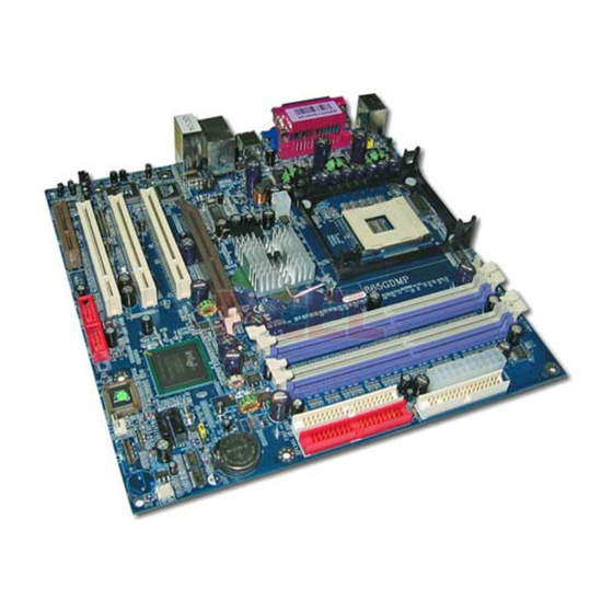
Page 7: Layout Diagram & Jumper Setting
1-4 Layout Diagram & Jumper Setting PRINT PS/2 Mouse LINE-IN PS/2 Keyboard LINE-OUT VGA/COM2 COM1 USB1 (Option) VGA (for 865GDM/865GDMP) COM2 (for 865PEDM/865PEDMP) ATX 12V Power Connector CPU Socket PS2 KB/Mouse Port CPU FAN K/B Power ON Jumper (JP1) ATX Power Connector PC99 Back Panel... -
Page 8: Expansion Sockets
(for 865PEDM/865PEDMP) Floppy Driver Connector 34-pin Block P.12 IDE1/IDE2 Primary/Secondary 40-pin Block P.13 SATA1, SATA2 Serial-ATA Port Connector 7-pin Block P.14 Only for 865GDM/865GDMP Headers Header Name Description Page AUDIO Line-Out, MIC Headers 9-pin Block P.14 USB2,USB3 USB Port Headers 9-pin Block P.14... -
Page 9: Chapter 2 Hardware Installation
Hardware installation 2-1 Hardware installation Steps Before using your computer, you had better complete the following steps: 1. Check motherboard jumper setting 2. Install CPU and Fan 3. Install System Memory (DIMM) 4. Install Expansion cards 5. Connect IDE and Floppy cables, Front Panel /Back Panel cable 6. -
Page 10: Install Cpu
When setting Enabled you can using keyboard by key in password/USB device to power on system. 1-2 closed K/B Power ON Disabled (Default) 2-3 closed K/B Power ON Enabled 1-2 closed USB Wake-Up Disabled (Default) 2-3 closed USB Wake-Up Enabled 2-3 Install CPU 2-3-1 Glossary Chipset (or core logic) - two or more integrated circuits which control the interfaces between... -
Page 11: About Intel Pentium 4 478-Pin Cpu
This motherboard provides a 478-pin surface mount, Zero Insertion Force (ZIF) socket, referred to as the mPGA478B socket supports Intel Pentium 4 processor in the 478 Pin package utilizes Flip-Chip Pin Grid Array (FC-PGA2) package technology. The CPU that comes with the motherboard should have a cooling FAN attached to prevent overheating. -
Page 12: Expansion Card
Dual channel function only supports when 2 DIMM Modules plug in either both DIMM1 & DIMM3 or DIMM2 &DIMM4, or four DIMM Modules plug in DIMM1~DIMM4. DIMM1 & DIMM3, or DIMM2 & DIMM4 must be the same type, same size, same frequency for dual channel function. -
Page 13: Assigning Irq For Expansion Card
Standard Interrupt Assignments Priority Standard function System Timer Keyboard Controller Programmable Interrupt Communications Port (COM2) Communications Port (COM1) Sound Card (sometimes LPT2) Floppy Disk Controller Printer Port (LPT1) System CMOS/Real Time Clock ACPI Mode when enabled 10 * IRQ Holder for PCI Steering 11 * IRQ Holder for PCI Steering 12 *... -
Page 14: Agp Slot
IMPORTANT! Before you plug-in AGP card, please make sure the following notice is fully understood and practiced. If your AGP card has “AGP 4X notch (show below) please make sure your AGP card is AGP 4X/8X (1.5V/0.8V) not AGP 2X (3.3V) 2x notch 4x notch AG P SLO T... - Page 15 Audio input to sound chip MIC : Microphone Connector VGA Connector (15-pin D-Sub) Connector: VGA (for 865GDM/865GDMP only) VGA is the 15-pin D-Subminiature female connector for display monitor. Serial Port COM1/COM2: COM1/COM2 (COM2 only for 865PEDM/865PEDMP) COM1/COM2A is the 9-pin D-Subminiature mail connector. The On-board serial port can be disabled through BIOS SETUP.
- Page 16 Pin 1 Floppy Drive Connector (11) Primary IDE Connector (40-pin block): IDE1 This connector supports the provided IDE hard disk ribbon cable. After connecting the single plug end to motherboard, connect the two plugs at other end to your hard disk(s). If you install two hard disks, you must configure the second drive to Slave mode by setting its jumpers accordingly.
-
Page 17: Headers
2-6-2 Headers Line-Out, MIC Header (9-pin): AUDIO This header connect to Front Panel Line-out, MIC connector with cable. AUDIO AUD - FPO UT - L AUD - R ET - L HP - O N AUD - RET - R AUD - FPO UT - R AUD - VC C AUD - MIC - BIAS... - Page 18 SPEAK JW_FP Pin 1 Pin 1 System Case Connections (8) Wake On-LAN Headers (3-pin) : WOL This connector connects to a LAN card with a WAKE ON-LAN output. This connector power up the system when a wake up signal is received through the LAN card. NOTE: This feature requires that Wake On LAN or Ring In Wake up is enabled.
- Page 19 (10) IR infrared module Headers (5-pin) : IR This connector supports the optional wireless transmitting and receiving infrared module. You must configure the setting through the BIOS setup to use the IR function. Pin 1 IR infrared module Headers (11) CD Audio-In Headers (4-pin) : CDIN CDIN are the connectors for CD-Audio Input signal.
-
Page 20: Starting Up Your Computer
1. After all connection are made, close your computer case cover. 2. Be sure all the switch are off, and check that the power supply input voltage is set to proper position, usually in-put voltage is 220V∼240V or 110V∼120V depending on your country’s voltage used. -
Page 21: Chapter 3 Introducing Bios
Chapter 3 Introducing BIOS The BIOS is a program located on a Flash Memory on the motherboard. This program is a bridge between motherboard and operating system. When you start the computer, the BIOS program gain control. The BIOS first operates an auto-diagnostic test called POST (power on self test) for all the necessary hardware, it detects the entire hardware device and configures the parameters of the hardware synchronization. -
Page 22: The Main Menu
3-3 The Main Menu Once you enter Award BIOS CMOS Setup Utility, the Main Menu (Figure 3-1) will appear on the screen. The Main Menu allows you to select from fourteen setup functions and two exit choices. Use arrow keys to select among the items and press <Enter> to accept or enter the sub-menu. -
Page 23: Standard Cmos Features
Load Optimized Defaults Use this menu to load the BIOS default values that are settings for optimal performances system operations. Load Standard Defaults Use this menu to load the BIOS default values that are factory settings for the stable performance system operation. Set Supervisor/User Password Use this menu to set User and Supervisor Passwords. -
Page 24: Advanced Bios Features
The time format is <hour><minute><second>. Primary Master/Primary Slave Secondary Master/Secondary Slave Press PgUp/<+> or PgDn/<–> to select Manual, None, Auto type. Note that the specifications of your drive must match with the drive table. The hard disk will not work properly if you enter improper information for this category. - Page 25 Allows you to choose the VIRUS Warning feature for IDE Hard Disk boot sector protection. If this function is enabled and someone attempt to write data into this area, BIOS will show a warning message on screen and alarm beep. Disabled (default) No warning message to appear when anything attempts to access the boot sector or hard disk partition table.
-
Page 26: Advanced Chipset Features
Keystrokes repeat at a rate determined by the keyboard controller. When enabled, the typematic rate and typematic delay can be selected. The settings are: Enabled/Disabled. Typematic Rate (Chars/Sec) Sets the number of times a second to repeat a keystroke when you hold the key down. The settings are: 6, 8, 10, 12, 15, 20, 24, and 30. -
Page 27: Dram Timing Settings
Select Enabled allows caching of the video BIOS, resulting in better system performance. However, if any program writes to this memory area, a system error may result. The settings are: Enabled and Disabled. Memory Hole At 15M-16M You can reserve this area of system memory for ISA adapter ROM. When this area is reserved, it cannot be cached. -
Page 28: Integrated Peripherals
CMOS Setup Utility – Copyright(C) 1984-2003 Award Software Integrated Peripherals > Onboard IDE Function Press Enter Item Help > Onboard Device Function Press Enter > Onboard Super IO Function Press Enter Init Display First PCI Slot Menu Level > Power On Function Button Only KB Power On Password Enter... -
Page 29: Onboard Device Function
The integrated peripheral controller contains an IDE interface with support for two IDE channels. Select Enabled to activate each channel separately. The settings are: Enabled and Disabled. Primary/Secondary Master/Slave PIO The four IDE PIO (Programmed Input/Output) fields let you set a PIO mode (0-4) for each of the four IDE devices that the onboard IDE interface supports. -
Page 30: Onboard Super Io Function
Select Enabled if your system contains a Universal Serial Bus (USB) controller and you have a USB keyboard. The settings are: Enabled, Disabled. On-Chip Serial ATA The settings are: Disabled, Auto, Combined Mode, Enhanced Mode, SATA Only. Default setting is Auto. Due to the Intel ICH5 Specification limited only provided two controllers. -
Page 31: Power Management Setup
: Standard Parallel Port : Enhanced Parallel Port : Extended Capability Port SPP/EPP/ECP/ECP+EPP To operate the onboard parallel port as Standard Parallel Port only, choose “SPP.” To operate the onboard parallel port in the EPP modes simultaneously, choose “EPP.” By choosing “ECP”, the onboard parallel port will operate in ECP mode only. -
Page 32: Pm Timer Reload Events
This determines the manner in which the monitor is blanked. DPMS (default) Initial display power management signaling. Blank Screen This option only writes blanks to the video buffer. This selection will cause the system to turn off the vertical and horizontal V/H SYNC+Blank synchronization ports and write blanks to the video buffer. -
Page 33: Pnp/Pci Configuration Setup
Interconnect, is a system which allows I/O devices to operate at speeds nearing the speed the CPU itself uses when communicating with its own special components. This section covers some very technical items and it is strongly recommended that only experienced users should make any changes to the default settings. -
Page 34: Irq Resources
CMOS Setup Utility – Copyright(C) 1984-2003 Award Software IRQ Resources IRQ-3 assigned to PCI Device Item Help IRQ-4 assigned to PCI Device IRQ-5 assigned to PCI Device IRQ-7 assigned to PCI Device Menu Level >> IRQ-9 assigned to PCI Device IRQ-10 assigned to PCI Device... -
Page 35: Miscellaneous Control
This section is for setting CPU Frequency/Voltage Control. CMOS Setup Utility – Copyright(C) 1984-2003 Award Software Miscellaneous Control CPU Clock Ratio Item Help Auto Detect PCI Clk Enabled Spread Spectrum Disabled ** Current Host Clock is 100/33MHz ** Menu Level > HOST/PCI Clock at Next Boot is 100/33MHz ** Current DRAM Clock is 133MHz **... -
Page 36: Load Standard/Optimized Defaults
When you press <Enter> on this item, you get confirmation dialog box with a message similar Load Standard Defaults (Y/N)? N Pressing <Y> loads the BIOS default values for the most stable, minimal-performance system operations. Load Optimized Defaults When you press <Enter> on this item, you get a confirmation dialog box with a message similar to: Load Optimized Defaults (Y/N)? N Pressing <Y>... -
Page 37: Magic Install Supports Windows 98Se/Me/Nt4.0/2000/Xp
From MAGIC INSTALL MENU you may make 10 selections: 1. INF install Intel 865 chipset system driver 2. VGA install Intel 865G VGA driver (Only for 865GDM/865GDMP) 3. SOUND install ALC AC97’ Codec Audio driver 4. LAN install VIA LAN Controller driver (for 865GDMP/865PEDMP) 5. -
Page 38: Inf Install Intel 865 Chipset System Driver
1. Click INF in the MAGIC INSTALL MENU 2. Click NEXT when Chipset Software Install Utility appears 3. This license agreement appear , click Yes , 4. Select if you want computer re-started click the readme information appear , click Next Finish NOTE: MAGIC INSTALL will auto detect file path X:\INTEL845\INF\SETUP.EXE This driver supports WINDOWS 98SE/ME/2000/XP... -
Page 39: Sound Install Alc Ac97 Codec Audio Driver
Click YES, This is Announce CopyRight If You Want Re-start Computer , Click FINISH 4-3 SOUND install ALC AC97 Codec Audio Driver 1. Click SOUND when MAGIC INSTALL 2. Then auto detect operation system language MENU appears edition, click OK, start to install DRIVER 3. -
Page 40: Lan Install Via 6105 Lan Controller Driver
5. Sound Effect select and KaraOK Mode 6. Manual Sound Effect Setting Function Note: The path of the file For WIN98/NT4.0/WIN2K/XP is X:\CODEC\ALC\SETUP.EXE Note: In Win2K/WinME users have to click Control Panel\System\Device Manager\ DVD\CD-ROM drives to Enabled digital CD Audio for the CD-ROM Device when use the SPDIF-Out digital signal. -
Page 41: Usb2.0
4-5 USB2.0 install Intel USB2.0 Driver Windows 98SE/ME USB 2.0 Driver installation 1. Click USB2.0 when Magic Install Menu 2. This license agreement appear, click Yes, then appear finish install driver , click Close and restart your computer Windows 2000/XP USB 2.0 Driver installation Windows 2000 Mothed1 Start Windows 2000 OS and Internet Connect, Select "Windows Update", Select Driver Update, Install Windows2000 USB2.0 Driver... -
Page 42: How To Utilize Pc-Health
3. This to assign the path of the file, click NEXT 4. Click FINISH after the software is installed NOTE: MAGIC INSTALL will auto detect file path X:\INTEL865\HEALTH\SETUP.EXE This driver supports WINDOWS 95/98/98SE/NT4.0/2000 4-6-1 HOW TO UTILIZE PC-HEALTH 1. Click START/PROGRAMS/ITE SMART 2. - Page 43 DIRECTX8.1 1. Click Magic BIOS when Magic Install 2. Click Next to install the Magic BIOS in MENU appears Destination Folder 3. After finish Setup you will have a Magic 4. Double click the Magic BIOS icon you will BIOS icon in your screen have this picture, choose from internet you can upgrade BIOS On-line 5.
-
Page 44: Pc-Cillin Install Pc-Cillin2002 Anti-Virus Program
Click Yes if you want to update the BIOS When System programming BIOS don’t turn otherwise choose No to exit off power, after finish update BIOS, the system will clear CMOS and automatically Restart When choose From Local Driver to update 10. - Page 45 3. This is license agreement, select "I Accept 4. Click NEXT and Enter your Customer the terms" and Click NEXT Information, Click NEXT or choose Change to change the path for the file to be stored 5. Click INSTALL, Start to install the software 6. Setup Complete and click FINISH 7.
-
Page 46: How To Update Bios
STEP 2. Copy utility program to your boot disc. You may copy from DRIVER CD X:\FLASH\AWDFLASH.EXE or download from our web site. STEP 3. Copy latest BIOS for 865GDM/865PEDM from our web site to your boot disc. STEP 4. Insert your boot disc into A:, start the computer, type “Awdflash A:\865GDMAxxx.BIN /SN/PY/CC/R”...