Table of Contents
Advertisement
Available languages
Available languages
GASOLINE BLOWER
SOUFFLEUR A ESSENCE
SOPRADOR DE GASOLINA
INSTRUCTION MANUAL
INSTRUCTIONS D'EMPLOI
INSTRUCCIONES DE MANEJO
BBX7600N
Important:
Read this instruction manual carefully before putting the Blower into operation and
strictly observe the safety regulations! Preserve instruction manual carefully!
Importante:
Lisez attentivement ce manuel utilisateur avant de mettre en route le sou eur et
respectez scrupuleusement les consignes de sécurité.
Conservez soigneusement ce manuel.
Importante:
Lea bien este manual antes de poner el soplador en funcionamiento, y observe
estrictamente las medidas de seguridad. Conserve este manual de instrucciones.
English / Français / Spanish
Advertisement
Chapters
Table of Contents

Related Manuals for Makita BBX7600N


Summary of Contents for Makita BBX7600N
- Page 1 English / Français / Spanish GASOLINE BLOWER SOUFFLEUR A ESSENCE SOPRADOR DE GASOLINA BBX7600N INSTRUCTION MANUAL Important: Read this instruction manual carefully before putting the Blower into operation and strictly observe the safety regulations! Preserve instruction manual carefully! INSTRUCTIONS D’EMPLOI...
-
Page 2: Table Of Contents
Thank you very much for selecting the MAKITA blower. We are pleased Table of Contents to be able to o er you the MAKITA blower, which is the result of a long Page development program and many years of knowledge and experience. -
Page 3: Safety Instructions
SAFETY INSTRUCTIONS General Instructions • To ensure correct and safe operation, the user must read, understand and follow this instruction manual to assure familiarity with the handling of the blower (1). Users insufficiently informed will risk danger to themselves as well as others due to improper handling. •... - Page 4 Start the Blower only in accordance with the instructions. Do not use any other methods for starting the engine (6)! • Use the blower and the tools supplied only for applications specified. • Start the blower engine only after the entire tool has been assembled. Operation of the tool is permitted only after all the appropriate accessories are attached.
- Page 5 Use only genuine spare parts and accessories supplied by MAKITA. Use of non-approved accessories and tools means increased risk of accidents and injuries. MAKITA will not accept any liability for accidents or damage caused by the use of any non-approved attachment or accessories.
-
Page 6: Technical Data
Spark plug NGK CMR6A 0.028 – 0.031 in Noise Level 50Feet per ANSI B175-2-2000 Notes: 1. Use the oil and spark plug speci ed by MAKITA. 2. This speci cation is subject to change without prior notice. -
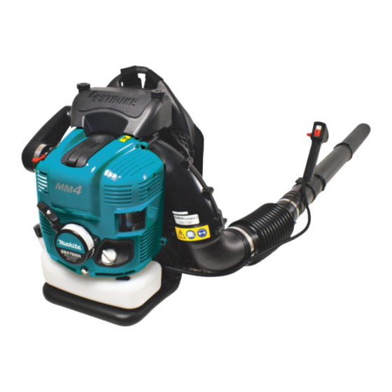
Page 7: Designation Of Parts
DESIGNATION OF PARTS OPTION DESIGNATION OF PARTS DESIGNATION OF PARTS DESIGNATION OF PARTS DESIGNATION OF PARTS 1. Stop switch 8. Choke Lever 15. Plug Cover 22. Blower Pipe 2. Control Handle 9. Starter Handle 16. Spark Plug 23. Blower Nozzle L=200 3. -
Page 8: Assembly Instructions
ASSEMBLY INSTRUCTIONS ASSEMBLY OF BLOWER PIPES CAUTION : Before performing any work on the blower, always stop the engine and pull the spark plug connectors off the spark plug. Always wear protective gloves! CAUTION : Start the blower only after having assembled it completely. 1. - Page 9 ATTACHING THE SHOULDER STRAP Attachment Procedure Attaching the shoulder strap to the blower. • Loop the end of the strap through the lower part of the hanger as shown in the figure at right. The side of the strap that has the folded tip should be facing outwards.
-
Page 10: Before Starting The Engine
Upper limit Remain 100 mL Lower limit Recommended oil: MAKITA genuine oil or SAE10W-30 oil of API type SF grade or better (4 stroke motor oil for automobiles) Oil capacity: Approximately 0.22 L (220 ml) CAUTION • If the blower is not stored in an upright position, the oil may flow from the level gauge into the engine and give a false reading when checking the oil level. -
Page 11: Fuel Supply
2. Fuel supply WARNING • When supplying the fuel, be sure to observe the following instructions to prevent ignition or fire: − Fuel supply must be made in a place free of fire. Never bring the fire (smoking, etc.) near to the place of fuel supply. −... -
Page 12: Operation
OPERATION 1. Starting WARNING • Never attempt engine start in a place where the fuel has been supplied. When starting the engine, keep a distance of at least 3 m. − Otherwise, it will may cause ignition or fire. • Exhaust gas from the engine has toxic consequences. Do not operate the engine in a poorly-ventilated place, such as in a tunnel, building, etc. −... -
Page 13: Adjustment Of Idling
NOTE • The engine may be damaged if the choke lever is moved further beyond the “CLOSE” position. • If the engine stops with an explosion sound or if the engine started, but stopped before operation of the choke lever, return this lever to the “OPEN”... -
Page 14: Operation Method
OPERATION METHOD 1. Adjusting Shoulder strap To loosen straps To tighten straps Adjust the shoulder strap to a length that is comfortable to work while carrying the blower. Adjust as shown in the figure. 2. Adjusting the control lever Move the control handle along the swivel pipe to the most comfortable position. -
Page 15: Inspection And Maintenance
INSPECTION AND MAINTENANCE DANGER • Before inspection and maintenance, stop the engine and allow it to cool. Remove also the spark plug and plug cap. − If inspection or maintenance is attempted immediately after engine stop or with the plug cap left attached, the operator may suffer burn or an accident due to careless startup. -
Page 16: Checking The Spark Plug
2. Cleaning of air cleaner Knob bolt WARNING INFLAMMABLES STRICTLY PROHIBITED Element cover Interval of Cleaning and Inspection: Daily (every 10 operating hours) (1) Loosen the knob bolt. (2) Remove the air cleaner cover. (3) Take out the element and remove any dirt with the brush. Note: The element is a dry type and should not get wet. -
Page 17: Storage
4. Cleaning the fuel filter • Clogged fuel filter may cause difficulty of start-up or failure of engine speed increase. • Check the fuel filter regularly as follows: (1) Remove the fuel tank cap, drain the fuel to empty the tank. Check the tank inside for any foreign materials. -
Page 18: Fault Location
Fault location Fault System Observation Cause Engine not starting or with Ignition system Ignition spark O.K. Fault in fuel supply or compression system, mechanical difficulty defect No ignition spark STOP-switch operated, wiring fault or short circuit, spark plug or connector defective, ignition module faulty Fuel supply Fuel tank filled Incorrect choke position, carburetor defective, fuel supply line... -
Page 19: Troubleshooting
TROUBLESHOOTING Before making a request for repairs, check a trouble for yourself. If any abnormality is found, control your machine according to the description of this manual. Never tamper or dismount any part contrary to the description. For repairs, contact Authorized Service Agent or local dealership. State of abnormality Probable cause (malfunction) Remedy... - Page 20 MAKITA LIMITED ONE YEAR WARRANTY Warranty Policy Every Makita tool is thoroughly inspected and tested before leaving the factory. It is warranted to be free of defects from workmanship and materials for the period of ONE YEAR from the date of original purchase. Should any trouble develop during this one year period, return the COMPLETE tool, freight prepaid, to one of Makita’s...
- Page 21 EMISSION COMPLIANCE PERIOD For handheld engines : The Emissions Compliance Period referred to on the Emissions Compliance label indicates the number of operating hours for which the engine has been shown to meet Federal emission requirements. Category C=50 hours, B=125 hours, and A=300 hours. Air Index and durability period information The Air Index Information hang-tag for this engine is provided in accordance with the California emission regulations.
- Page 22 EMISSION COMPONENT DEFECT WARRANTY COVERAGE - This emission warranty is applicable in all States, except the State of California Makita U.S.A., Inc., (herein "Makita") warrant to the initial retail purchaser and each subsequent owner, that this utility equipment engine (herein "engine") was designed, built, and equipped to conform at the time of initial sale to all applicable regulations of the U.S.
- Page 23 As the engine owner, you are responsible for the performance of the required maintenance listed in your owner's manual, Makita recommends that you retain all receipts covering maintenance on your engine, but Makita can not deny warranty solely for the lack of receipts or for your failure to ensure the performance of all scheduled maintenance.
- Page 24 ON THE OUTCOME OF A WARRANTY CLAIM. If other than the parts authorized by Makita are used for maintenance replacements or for the repair of components affecting emission control, you should assure yourself that such parts are warranted by their manufacturer to be equivalent to the parts authorized by Makita in their performance and durability.
- Page 25 As the small off-road engine owner, you should however be aware that Makita USA, Inc may deny you warranty coverage if your small off-road engine or a part has failed due to abuse, neglect, or improper maintenance or unapproved modifications.
- Page 26 (1) Any warranted part that is not scheduled for replacement as required maintenance in the written instructions required by subsection (d) must be warranted for the warranty period defined in Subsection (b)(2). If any such part fails during the period of warranty coverage, it must be repaired or replaced by the manufacturer according to Subsection (4) below.
- Page 27 (iii) Spark advance/retard system. Miscellaneous Items Used in Above Systems Hoses, Sealing gaskets, belts, connectors, and assemblies. Makita USA, Inc will furnish with each new engine written instructions for the maintenance and use of the engine by the owner. MAINTENANCE STATEMENTS...
-
Page 28: Symboles
Frenç ais Vous venez d’acheter un sou eur MAKITA, fruit d’importants Table des Matières programmes de développement et de nombreuses années d'études et Page d’expérience et nous vous en remercions. Symboles ..................28 Consignes de sécurité ............29-30 Les modèles BBX7600N légers, pratiques et compacts, Caractéristiques techniques ............ -
Page 29: Consignes De Sécurité
CONSIGNES DE SECURITE Généralités • Pour tirer le meilleur parti de votre machine, vous devez lire, assimiler et respecter les instructions figurant dans ce manuel (1). Les utilisateurs mal informés risquent, par des manipulations inappropriées, de se blesser ou de blesser leur entourage. •... - Page 30 Avant de mettre la machine en marche, assurez-vous que toutes les instructions sont bien respectées. N’utilisez pas d’autres méthodes de mise en marche de l'appareil (6). • N’utilisez la machine et les outils fournis que pour les applications spécifiées. • Ne mettez la machine en marche que lorsque tous les accessoires ont été...
- Page 31 N’utilisez-que des pièces et des accessoires d’origine, fournis par MAKITA. L'utilisation d’outils et d’accessoires non agréés augmente les risques d’accident. MAKITA décline toute responsabilité en cas d’accident ou de dommage provoqué par l’utilisation d’accessoires ou d’outils non agréés.
-
Page 32: Caractéristiques Techniques
NGK CMR6A Distance entre é Niveau de bruit (15 metres par ANSI B175-2-2000) Notes: 1. Utiliser l ’huile et la bougie d ésign és par MAKITA. 2. La sp éci cation peut être soumise à changement sans avis pr éalable. -
Page 33: Liste Des Pièces
LISTE DES PIÈCES Optionnel Désignation des pièces Désignation des pièces Désignation des pièces Désignation des pièces 1. Interrupteur d’arrêt 8. Levier d’étrangleur 15. Capot de bougie 22. Tube de souffleur 2. Poignée de contrôle 9. Poignée de démarrage 16. Bougie 23. -
Page 34: Instructions De Montage
INSTRUCTIONS DE MONTAGE Montage du tube de soufflante ATTENTION : Avant toute opération sur le souffleur, coupez toujours le moteur et débrancher les connecteurs de bougie. Portez toujours des gants de protection! ATTENTION: Ne mettre le souffleur en marche que lorsqu’il est complètement monté. - Page 35 Fixation de la bandoulière Procédure de fixation • • • •...
-
Page 36: Avant De Démarrer Le Moteur
AVANT DE DÉMARRER LE MOTEUR 1. Vérification et remplissage de l’huile Huile recommandée Capacité d’huile Précaution • • Vérification point #1 : Concernant le bouchon à huile lors du ravitaillement • • Vérification point #2 : Si l’huile se renverse lors du ravitaillement •... - Page 37 2. Alimentation en carburant AVERTISSEMENT • − − − − − • − Durée de stockage du carburant Entrepôsage de l’appareil et du réservoir de ravitallement • • Carburant Les essentiels pour le carburant • • Ravitaillement • • • •...
-
Page 38: Fonctionnement
FONCTIONNEMENT 1. Mise en marche AVERTISSEMENT • − • − • − • 1) Quand le moteur est froid, ou quand du carburant a été ravitaillé. Fermer... -
Page 39: Réglage Du Ralenti
NOTE • • • • • 2) Quand le moteur est échauffé 2. Arrêt 1) Lorsque le levier du régulateur de vitesse est placé sur la position petite vitesse. 2) Lorsque le levier du régulateur de vitesse est placé sur une position autre que la petite vitesse. -
Page 40: Mode Opératoire
MODE OPERATOIRE 1. Réglage de la bandoulière Réglage du levier du régulateur 3. Manoeuvre du souffleur Petite vitesse : Feuilles sèches et gazon Grande vitesse : Gravier et terre Si vous soulevez le levier du régulateur de vitesse, le TPM du moteur augmente. -
Page 41: Inspection Et Maintenance
INSPECTION ET MAINTENANCE DANGER • − • 1. Remplacement de l’huile à moteur DANGER • • Intervalle de remplacement: Huile recommandée: Procédure de changement de l’huile Précaution Précaution Précaution L’essentiel lors de remplacement de l’huile à moteur • •... - Page 42 2. Nettoyage du filtre à air DANGER DEFENSE DE FAIRE DU FEU Intervalle de nettoyage et de contrôle : Quotidien (toutes les 10 heures de marche) DANGER • • 3. Vérification de bougie d’allumage ATTENTION • • •...
-
Page 43: Remisage
4. Nettoyage du filtre à carburant • Le filtre à carburant colmaté peut causer un démarrage difficile ou une défaillance de la montée de vitesse du moteur. • Vérifier régulièrement le filtre à carburant comme ce qui suit: (1) Démonter le bouchon de vidange du réservoir de carburant, évacuer le carburant pour vider le réservoir. - Page 44 Localisation des défauts...
-
Page 45: Dépannage
DEPANNAGE Etat d’anomalie Cause probable (fonctionnement irrégulier) Remède... - Page 46 Si un problème quelconque devait survenir au cours de cette période d’un an, veuillez retourner l’outil COMPLET, port payé, à une usine ou à un centre de service après-vente Makita. Makita réparera l’outil gratuitement (ou le remplacera, à sa discrétion) si un défaut de fabrication ou un vice de matériau est décou- vert lors de l’inspection.
-
Page 47: Símbolos
Spanish Muchas gracias por comprar el soplador MAKITA. Nos complace Contenidos recomendarle el uso del soplador MAKITA que es el resultado de un Página extenso programa de investigación desarrollado tras años de estudio Símbolos ..................47 y experiencia. Instrucciones de Seguridad ............ 48-50 Datos Técnicos................ -
Page 48: Instrucciones De Seguridad
INSTRUCCIONES DE SEGURIDAD Instrucciones Generales • Para asegurar un funcionamiento correcto y seguro, el usuario debe leer, comprender y seguir este manual de instrucciones para familiarizarse con el soplador (1). Los usuarios que no se informen suficientemente, ocasionarán un peligro a s’í mismos y a otros. •... - Page 49 Arrancar el soplador sólo de acuerdo con las instrucciones. ¡ No utilizar cualquier otro método para arrancar el motor (6) ! • Utilizar el soplador y las herramientas suministradas sólo para las aplicaciones establecidas. • Arrancar el soplador sólo despues de completar el montaje de la máquina.
- Page 50 • Clase de heridas. • Su nombre. (12) EMBALAJE El soplador MAKITA se suministra en una caja protectora de cartón para impedir daños durante el transporte. El cartón es una materia primaria básica y puede ser reutilizado consecuentemente o reciclado.
-
Page 51: Datos Técnicos
Bujías NGK CMR6A 0.028 – 0.031 in Nivel de ruido 50Feet según ANSI B175-2-2000 NOTA: 1. Utilice el aceite y la bujá de alta tension designados por Makita. 2. Las especi caciones se podrán modi car sin previo aviso. -
Page 52: Denominación De Partes
DENOMINACIÓN DE PARTES OPCIÓN DENOMINACIÓN DE PARTES DENOMINACIÓN DE PARTES DENOMINACIÓN DE PARTES DENOMINACIÓN DE PARTES 1. Interruptor de paro 8. Palanca de choque 15. Tapa de la bujia 22. Tubo de soplador 23. Boquilla de Soplador 2. Palanca de control 9. -
Page 53: Instrucciones De Montaje
INSTRUCCIONES DE MONTAJE Ensamblaje de los tubos del soplador PRECAUCION : Antes de efectuar cualquier trabajo en el soplador, siempre detener el motor y separar los conectores de la bujía. Siempre llevar guantes protectores. PRECAUCION : Arrancar el soplador sólo después de ensamblarlo completamente. - Page 54 Instalación de la correa al hombro Procedimiento de instalación Instalación de la correa al hombro en el soplador. • Haga un bucle en la punta de la correa por la parte inferior del soporte como aparece en la figura de la derecha. El lado de la correa con la punta plegada debe tirar hacia afuera.
-
Page 55: Antes De Poner En Marcha El Motor
Quedan 100ml aceite.) Límite inferior Aceite recomendado: Aceite auténtico MAKITA o aceite SAE10W-30 o de tipo API grado SF o mejor (motor de 4 carreras 4 para automóviles) Capacidad de aceite: Aproximadamente 0,22 L (220 ml) Precaución: • Si no guarda el soplador en posición vertical, el aceite puede fluir del medidor de nivel hacia el motor y producir una lectura falsa cuando inspeccione el nivel de aceite. - Page 56 2. Abastecimiento de combustible ALARMA • Observe bien los siguientes puntos cuando se abastece el combustible. Podrá causar ignición o incendio. − Pare el motor y efectué el abastecimiento cuando el motor queda enfriado. − El tapón del tanque de combustible lleno debe abrirse lentamente. Podrá saltar el combustible por la presión interior. −...
-
Page 57: Operación
OPERACIÓN 1. Modo de arranque ALARMA • No deje arrancar el motor en el lugar donde se ha abastecido el combustible.Debe arrancarse en un lugar donde queda más de tres metros de distancia. − Podrá causar ignición o incendio. • Gas de escape del motor es venenoso. No lo utilice en un lugar sin ventilación adecuada tales como en el interior, túnel, etc. −... -
Page 58: Ajuste Del Ralentí
NOTA • La palanca de choque, si se levanta de la posición “cerrada” hacá arriba, podrá dañarse. • Cuando para el motor con explosión o para el motor arrancado antes de que se haga funcionar la palanca de choque, vuelva la palanca de choque a la posición “abierta”... -
Page 59: Procedimiento De Operación
PROCEDIMIENTO DE OPERACIÓN 1. Ajuste de la correa al hombro Para apretar las correas Para aflojar las correas Ajuste la correa al hombro a una longitud que le resulte cómoda para trabajar mientras lleva el soplador. Ajuste tal como aparece en la figura. 2. -
Page 60: Inspección Y Mantenimiento
INSPECCIÓN Y MANTENIMIENTO PRECAUCIÓN • Antes de efectuar la inspcción y mantenimiento, detenga el motor y efectúe la operación después de que se haya enfriado el motor. Asimismo, quite la bujía de alta tensión y el tapón de lal bujía. −... - Page 61 2. Limpieza del depurador de aire Perno de perilla PELIGRO: Los materiales inflamables están estrictamente prohibidos Cubierta del elemento Intervalo de limpieza e inspección: diariamente (cada 10 horas de funcionamiento) (1) Afloje el perno de la perilla. (2) Desmonte la cubierta del depurador de aire. (3) Saque el elemento y elimine la suciedad con el cepillo.
-
Page 62: Almacenamiento
4. Limpieza del filtro de combustible • Cuando el filtro de combustible está atascado, el arranque podrá ser difícil o la volocidad del motor no podrá aumentarse. • Compruebe el filtor de combustible según las siguientes instrucciones periódicamente. (1) Quite el tapón del tanque de combustible y saque el combustible para que quede sin combustibe. - Page 63 Localización de averías Avería Sistema Observaciones Causas El motor no arranca o lo Encendido Hay chispa de Fallo en suministro de combustible o sistema de hace con dificultades encendido compresiónDefecto mecánico No hay chispa Interruptor STOP conectado, fallo del cableado o cortocircuito, bujia o conector defectuosos, fallo en el módulo de encenidido Suministro de...
-
Page 64: Investigación De Averías
INVESTIGACIÓN DE AVERÍAS Antes de solicitar reparaciones; compruebe el problema usted mismo. Si se encuentra una anormalidad, controle la máquina de acuerdo con la descripción de este manual. Nunca manipule ni desmonte piezas no relacionadas con la descripción. Para reparaciones, póngase en contacto con el Agente de Servicio Autorizado o concesionario local. - Page 65 Si durante este periodo de un año se desarrollase algún problema, retorne la herramienta COMPLETA, porte pagado con antelación, a una de las fábricas o centros de servicio autorizados Makita. Si la inspección muestra que el problema ha sido causado por mano de obra o material defectuoso, Makita la reparará...
- Page 66 WARNING: The Engine Exhaust from this product contains chemicals known to the state of California to cause cancer, birth defects or other reproductive harm. Makita Corporation 3-11-8, Sumiyoshi-cho, Anjo, Aichi 446-8502, Japan Owners Manual BBX7600N 12_10_29...