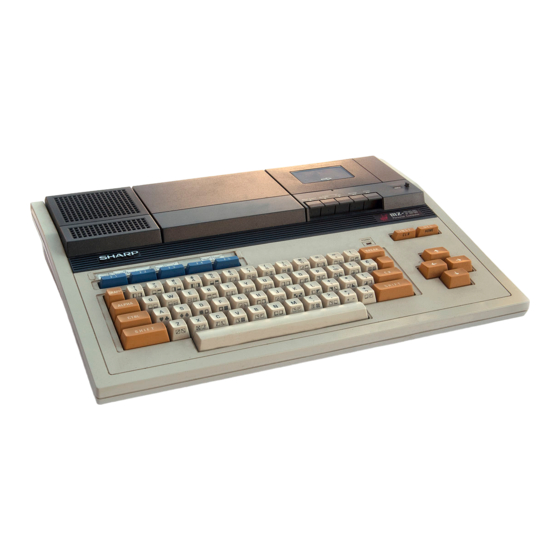
Sharp MZ-700 Service Manual
Hide thumbs
Also See for MZ-700:
- Basic manual (109 pages) ,
- Owner's manual (245 pages) ,
- Owner's manual (213 pages)
Table of Contents
Advertisement
Quick Links
MZ-700
SERVICE MANUAL
-r' .............................................................
. .
SHARP
INDEX
CODE: OOZMZ700SM I/E
PERSONAL
COMPUTER
MODEL
MZ-700
MZ-1TOl
MZ-1POl
(FOR THE MZ-lPOI MECHANICAL SECTION
REFER TO THE DPG2306 SERVICE MANUAL)
1.
SPECIFICATIONS. . .
.
.
.
.
.
.
.
. . .
.
.
.
. .. . . . . .
..
.
. .
. . .. . .
..
. .
..
1
2.
NAMES OF FUNCTIONAL COMPONENTS.
. .
.
. .
.
. .
. .
.
.
.
.
. .
.
.
..
2
3.
SYSTEM BLOCK DIAGRAM
.............................. _ ..
3
4.
SYSTEM DESCRIPTION.
.
.
.
.
.
. .
.
.
.
.
. •
. .
. .
.
.
.
.
.
.
.
. . •. . . .
.
. ..
4
5.
DATA RECORDER ....................................
....
15
6.
COLOUR ENCODER .......
.
........
.
.
..
......
.
............ 19
7.
MICRO COLOUR GRAPHIC
PRINTER
.........................
20
8.
POWER SUPPLy ...................
.
.............
•
........ 24
9.
IC SIGNAL POSITION
.......................•...........
.
.
27
10.
CIRCUIT DIAGRAM & PARTS LAyOUT ...•.
..
...
..
....
..
....
29
11.
PARTS GUIDE & LIST
SHARP CORPORATION
Advertisement
Table of Contents
Troubleshooting

Related Manuals for Sharp MZ-700


Summary of Contents for Sharp MZ-700
- Page 1 MZ-700 SERVICE MANUAL SHARP -r' ............. CODE: OOZMZ700SM I/E PERSONAL COMPUTER MZ-700 MODEL MZ-1TOl MZ-1POl (FOR THE MZ-lPOI MECHANICAL SECTION REFER TO THE DPG2306 SERVICE MANUAL) INDEX SPECIFICATIONS....
- Page 2 ~\~Z~ SPECIFICATION 1-1. MZ-700 1-3. Micro-colour graphics printer specification (option) Sharp LH0080A (Z-80A) Printing method Ball point pen recording, four colours 3.5MHz rotary selection type. Oock(ct» 4KB ROM (monitor) Memory Kind of colours black, 2 blue, 3 green, 4= red...
- Page 3 MZ-700 NAME OF FUNCTIONAL COMPONENT MZ-700 Front view plolter prioter recorder (cassette) INS. DEL key ":::d'---,----CUrSOI control keV$ Main kev board - - - - - ' MZ-700 Aeer view BrN-Colour switch Channel switch Composi! terminal socket plOHtr printer Dat8 recorder...
- Page 4 ~"q-700 3. SYSTEM BLOCK DIAGRAM A.C. 100V -"" ~PO~UP' R.G.B. MEMORY CONTRa. VIDEO RAM -.., :Ja:: llER (CRTC) PLY CIRCUIT ,.-- ...JU CHAR VIDEO RESET ..J Reset CIRCUITJ MAIN MEMORY 64KB DRAM MONITOR Z80A ,..\ ADDRESS BUS " ~dJA "...
- Page 5 SYSTEM DESCRIPTION 4-1. Memory map • Boot command: L a) At power on • With the entry of the boot command only the tape loading program is transferred to the system area and the $0000 $0000 SYSTEM (DRAM) MONITOR system program is loaded to the system area designated (ROM) TEXT AREA in the DRAM.
- Page 6 2. PAL system (U.K., Germany, etc.) $FOOO 3. SECAM system (French, etc.) Because of the different specification requirements above, MEMORY CHANGE the MZ-700 may not be suitable for overseas operation. ' - - Disable Enable PAL signal specification • When the...
- Page 7 To read the contents of a VRAM character, the CPU The signal that determines the function (shift LOAD: sends out the relevant address. When RD is forced low, the out or data set) of the shift register LS165. data is then read via the bidirectional buffer LS245. High state of this signal acts as shift and low However, the address range $0000 through $DFFF must state of this signal acts as data set.
- Page 8 \ ,'1Z -700 2) Memory controller • Custom LSI internal memory controller block diagram and description In the MZ· 700, it needs to segregate the memory in order to acheive the above mentioned memory mapping. The When the above mentioned OUT command is executed, address Ao ,.., A2 is stored in "FF"...
- Page 9 4-4. Memory controller (CRTC) circuit description The memory controller and the CRTC are contained in the single chip custom LSI (M60719). Memory controller signal description & Circuit diagram Signal name IN/OUT Function Pin No. signal name CPU address Bus Clock (17.7MHz) <I>...
- Page 10 < > CUSTOM LSI 1. BLOCK DIAGRAM CRT Control LPHI CLKN COLR r - - NTSC H. SYNC. (NTSC) BLNK SELECT "V HBLN BLNK0 H. SYNC. (PAL) I..- f---- COLR . .., LOAD NTPL SCREEN POSITION "U ::> SCREEN ::i: POSITION "...
- Page 11 Memory Management (1) • ,... IORN " PRCN ." " -" BLNK .." " '---- <C LACH (f.I ' " CSDD • INH1 INH2 " INH3 " RASN <C MRQN RFSN INH1 CSON '" INH2 WAIT WATN CYCLE INH3 CIRCUIT CSDN INH2...
- Page 12 NTPL GATE 4-3. Memory mapped I/O ($EOOO - $EOO8) Colour VRAM (VRAM-2) • MZ-700 colour infonnation is managed character by character. One byte of colour infonnation table is assign- Function memory Controller ed to each characters displayed on the TV screen.
- Page 13 • Output data handled in the bit cell mode. (Port C in control mode) b) Cassette controller Data transfer with the cassette recorder is carried out on PCI, PC4, and PC5 of the 8255. Shown next is the data format (Sharp PWM method) of the cassette tape.
- Page 14 _--464~- __ ... II.oo ... _ - 4 9 .• 4j.1S----I .. 240~-'- 264~'" -+oI ..1 - o 1 " I ;.' _ _ _ _ _ _ _ CASE1 LONG - - - - -..- - SHORT --J ' 368j.1S 368j.1S...
- Page 15 c) Keyboard controDer The 8255 writes strobe (key scan signals) on PA and reads key data from PB. The table shown below is the key map. d) Signals around the 8253 The 8253 Programmable Timer generates the buzzer tone 8253 through the counter and keeps the internal timer function via the counters #1 and #2.
- Page 16 DATA RECORDER 5-1. recorder (MZ-lT01) • Cassette specification Data Data transfer with the recorder carried out via the 8255. Method PWM recording method The read data is sent out through the port Cl and the Rated power O.25V write data is received through the port C5. The motor ±...
- Page 17 iv1Z 700 Troubleshooting procedure Phenomennon Motor and tape do not rotate, when the PLAY button is pushed. Motor fai lure Check if the SW302 interlinked with the Check if M+ Check +5V on REMOTE terminal P LAY push button is and M·5V are in supply.
- Page 18 Mechanical adjustments RECORD/FAST FORWARDjREWIND torque measure- Tape speed adjustment ments 1. Connect the wow-flutter measuring instrument to :f#!, 1. Set the torque measuring instrument on the cassette pin of the CNW3001 connector. tape recorder. 2. Playback the test tape (UKOG-0119CSZZ, MTT-1l3 2.
- Page 19 MZ~700 Cassette recorder waveforms Primary stage amplifier output wavefonn Operational amplifier input wavefonn Operational amplifier input wavefonn ® ® 6mv~ 1.8V Operational amplifier output wavefonn Operational amplifier input wavefonn Output wavefonn ® ® f1 " " 1.SVpp 4Vpp sVpp \lV""~'" Recording signal amplified wavefonn Recording signal amplified wavefonn Recording input wavefonn...
- Page 20 ~\;1Z 5-2. External recorder playback circuit When the external recorder is used, connection is made • 8-Pin DIN connector I VIDEO with the 8255 by shorting P-12. In this condition, the write data (8255 PC output) differentiated and sent 2 GND to the recorder.
- Page 21 MZ-700 MICRO COlOR GRAPHIC PRINTER Micro color graphic printer 1) Block diagram ..-- V-axis stepping motor Intelligent Drive array l-l. X-axis stepping Con- interfacing Buffer motor' nectar Pen up/ " Magnet down drive circuit "7 magnet I"'- Printer mechan ism...
- Page 22 2) Pen exchange method To remove pen, press the pen exchange button, when the It is more effective to save power to shut off current while the X and Y axis motors are at a halt. But, there slider is at the right handside, push the pen release lever. may be a possible malfuction because of unsuppressed Motor vibration, if the current is turned off with a normal...
- Page 23 MZ--700 [COLOUR PLOTTER PRINTER CONTROL LSI] Pin assignment Symbol Name In/out Function Ground Connected to QV. Connected to SV. Main power Power Connected to SV. PROG Program Not used. Port I Used as printer control signals. Plo - PI Used for data input port from CPU. Port 2 P20 - Do -D...
- Page 24 7-2. Interfacing with the MZ-700 Fig. 1 shows the block diagram for connection with the printer. Fig. 2 shows its circuit description. Fig. 3 shows the timing chart. Table of character set > "" " w m # 3 C S "v...
- Page 25 MZ-700 POWER SUPPLY Power supply circuit description (4) For circuit stabilization against load fluctuation, (1) AC source power is rectified through the diode bridge (RB-156). we use IC21 (shunt regulator), PC1 (photocoupler), and Q3 (transistor). When the gate of IC21 is above...
- Page 26 Waveform Waveform@ Waveform "1 320V -------ov _ _ _ _ _ ""' l ov 2·2. When extremely low output voltage is encountered Start Observe waveform between the collector and emitter of Q1 If Waveform @ If Waveform@ If Waveform(§) R9, C12, C", PC1, IC21, C25 R5, RS in failure in failure...
- Page 27 ~v1Z - 70C 2-4. Abnonnal increase of output ripple In case irregular increase seen for the output ripple like the one below, it needs to replace C22 and C23 with new ones because they have been fatigued. 1 00m V or less (Normal rippla) Input: AC220 - 240V Output: 5V,3.75A...
- Page 28 le SIGNAL POSITION 74LS02 74LSOO 74LS04 7417 74LS14 74LS32 5A 5Y IY 2A 2Y 3A 3Y GND 2A 2Y 3A 3Y GND 74LS86 74LS42 7472 \ICe 48 4A 4Y 38 3A VCC PR K3 K2 NC CLR J2 J3 2Y GND 74S157 74LS125A 74LS145...
- Page 29 74LS174 74LS176 74LS166 CLEAR IQ 2Q GNO CLEAR IQ 74LS273 74LS246 BD 70 2Q 3Q OUTPUT IQ ID 74LS367A 5A 5Y 4A VCC G2 2Y 3A 3Y GND...
- Page 30 MZ-700 . CIRCUIT DIAGRAM & PARTS LAYOUT...
- Page 37 Power unit Lt:. " t~/(OD Z0040 T500mA l.,L}, ZOQ74 10/2W RBt56 r%~~~----~--~ AC240V " 68 K/2W " 2201C/IW " l!",F/"OO .2 ESIF " ",OOP 331( •• R21 0 IIJ l000Jj/IO "0 ." .1." 25C31 3300pF/ .. OOV.2 " "I 2SC 12130 '"...
- Page 38 [Colour encoder circuit] ". '00" - " le, U/81 '" • zsc~~p SC!M~ ~U/III ICICl/SII • .." •• " • IClllIS, G I I / I I I " " • • .." '<3 MCI:S12P ." • • , H07"~P "...
- Page 39 [Motor P.W.B. unit] --I\fIIv-- TO MOTOR BLUE [A()'IOO2j MAIN ~:5005 ". " II WJ .~OJ o::~ ~~:~;" $""'00 REAO WRITE ---- •• r - - - - - f j-!" " ' " [Rot.Sf HEAD RECOROI 03001 25C16:52Q P\.AVBACK ><£40 03002"-03004 2SC2021R "...
- Page 40 [Data recorder circuit '" EI02IAC-33A...
- Page 43 MZ-700 & PARTS LIST GUIDE Parts marked with" L1I" is important for maintaining the safety of the set. Be sure to replace these parts with specified ones for maintaining the safety and .performance of the set.
- Page 44 14 XUPSD30P08000 Screw Lid for connector 15 GFTAR1012ACZZ Cushion for PWB fixing angle 16 PGUMS1266CCZZ Speaker 17 VSPOO80P-608N 18 HBDGBIOO2ACZZ Sharp badge 19 GCABA1006ACZZ Bottom cabinet 20 GLEGG1020CCZZ Rubber foot 21 HBDGDIOOIACZZ Model badge 22 QTANSIOO2ACZZ Ground terminal 23 TLABZ1009ACZZ...
- Page 45 MZ·700 CPU U~~t Exteriors...
- Page 46 MZ·700 Printer Unit Exteriors PRICE PART PARTS CODE DESCRIPTION RANK MARK RANK Top cabinet CCABB1006ACZZ CFTAT1001ACZZ Printer cover CSFTZ1001ACZZ Pa cer shaft unit Pacer holder NSFTZ1001ACZA NSFTZ1001ACZB Pacer shaft XRESJ40 6 0 0 0 E type ring DUNTM1051ACZZ Printer mechanism unit Paper feed key top J K N B Z 1 0 0 5 AC 01 LCHSM1004ACZZ...
- Page 47 MZ·700 CPU Unit Electronic Components PART PRICE PARTS CODE DESCRIPTION RANK MARK RANK 1 QCNCMI009ACZB Connector to Soeaker (2oin) 2 QCNCMI009ACZD Connector to Printer (4l)in) Connector to Colour encoder 3 QCNCMI009ACZL Connector to Printer 4 QCNCMI009ACZO 5 QCNCM1010ACZZ Connector to Power suoolv 6 QCNCMI0IIACZZ Connector Jov stick 7 QCNCWI013ACZZ...
- Page 48 MZ·700 CPU Unit Electronic Components PART PRICE DESCRIPTION PARTS CODE RANK MARK RANK Resistor (l/4W 3900 +5%) VRD-5T2EY391J Resistor (l/4W 4300 +5%) 5 T 2 E Y 4 3 1 J Resistor (l/4W 4700 +5%) 83 VRD 5 T 2 E Y 4 7 1 J Resistor (l/4W 47KO +5%) 84 VRD-5T2EY473J Resistor (l/4W 560 +5%)
- Page 49 MZ-700 Power Supply Unit PRICE PART PARTS CODE DESCRIPTION RANK MARK RANK 1 XBPSE30P08KSO Screw 2 PCOVS0181VAZZ Case (B) 3 TLABN0066PAZZ Label 4 DSOCN0344PAZZ Connector (out put) W.Wire 5 L B N 0 K 0 0 1 8 J B E 0...
- Page 50 MZ .. 700 Power Supply Unit 13------"~- _"'____tI 12----t--~~_~...
- Page 51 MZ·700 Board Unit PRICE PART PARTS CODE DESCRIPTION RANK MARK RANK OCFD5799D//// Soace key OCF3362A///// Crank guide F OCF3363A///// Crank shaft A OCF6303A///// Key contact OCF3357A///// Guide tiD OCF4906A///// Frame (NSH OCF3361A///// Crank holder F OCF3364A///// Return spring for 60 key) OCF3364B///// Return spring for shift key)
- Page 52 MZ·700 Ca ssette Unit PRICE PART PARTS CODE DESCRIPTION MARK RANK RANK 1 JKNBR0204AFSA Stop/Eject/Play/Rewind/F.Foward botton 2 JKNBR0204AFSB Record botton Taoe counter 3 KCOUB0138AFZZ 4 LANGF0744AFZZ Lock lever holding metal Wire holding metal (A) 5 LANGG0099AFFW 6 LANGG0100AFFW Wire holding metal (B) Taoe counter anlzle 7 LANGTl169AFFW Anllle for botton...
- Page 53 MZ·700 Cassette Unit PRICE PART PARTS CODE DESCRIPTION RANK MARK RANK P C U S F 0 0 1 8 A F 0 0 Cushion 82 HDECZ0063AFSA Miller plate 83 HPNLC1410AFSA Front cabinet 84 MSPRP0327AFFJ Cassette take out spring 85 PCUSG0204AFOO Cushion Bottom plate 86 GiTAU0020AFZZ...
- Page 54 [[] CASSETTE UNIT .-16 i / '...
- Page 55 MZ·700 -12-...
- Page 56 MZ-700 • Index PRICE NEW PART PRICE NEW PART PARTS CODE PARTS CODE RANK MARK RANK RANK MARK RANK MLEVFI441AFFW 8- 33 CCABBI005ACZZ 1- 25 MLEVF1442AFZZ CCABBI006ACZZ MLEVF1494AFFW 8- 74 CFTACI248AFOl MLEVP0417AFFW 8- 35 MLEVP0418AFFW 8- 36 CFTATIOOIACZZ 8- 76...
- Page 57 MZ·700 PRICE NEW PART PRICE NEW PART PARTS CODE PARTS CODE RANK MARK RANK RANK MARK RANK QCNW-1048ACZZ VCCSPU1HL391J 3- 17 QCNW 1049ACZZ 3- 90 VCCSPU1HL471J 3- 18 QCNW 1051ACZZ VCEAAA1CW106Q 3- 32 QCNW-1733AFZZ 8- 122 VCEAAA1CW22.6Q 3- 33 QFS-COO02PAZZ 6- 10 VCEAAA1HW105Q 3- 34...
- Page 58 MZ·700 PRICE NEW PART PRICE NEW PART PARTS CODE PARTS CODE RANK MARK RANK RANK MARK RANK OCF3876C///// 7- 19 V R D-S T 2 EE 2 0 5 J 8- 121 OCF3876D///// 7- 20 VRD-ST2EYIOIJ 6- 27 OCF3876E///// 7- 21 VRD ST2EYI02J 3- 68 OCF3876F/////...
- Page 59 MZ-700 SHARP 11-185121\0 71931-100 S!MMZ700!lT&1POl 203 - 250887!720g0700Q SHARP CORPORATION Industrial Instrument Group & Reliability Quality Control Center Yamatokoriyama. Nara 639-11. Japan March 1985 Printed in Japan...