
Related Manuals for Bosch D1255RB/D1256RB/D1257RB


Summary of Contents for Bosch D1255RB/D1256RB/D1257RB
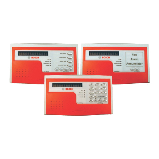
- Page 1 D1255RB/D1256RB/D1257RB Installation Instructions Fire Keypads and Fire Alarm Annunciator...
-
Page 2: Listings And Approvals
D1255RB/D1256RB/D1257RB | Installation Instructions | Listings and Approvals Listings and Approvals UL 365 Police Station Burglar Alarm Units and Systems Local Burglar Alarm Units and Systems UL 609 UL 864 Control Units for Fire-protective Signaling Systems UL 985 Household Fire Warning System Units... -
Page 3: Table Of Contents
Keypad (Command Center) Functions ..12 Table 2: Keypad or Annunciator Connections..8 Specifications ..........13 Table 3: Function List Description......11 Table 4: Specifications for the D1255RB and D1256RB Keypads and the D1257RB Annunciator..........13 Bosch Security Systems, Inc. | 8/06 | F01U011791B... -
Page 4: 1.0 Introduction
The D1255RB and D1256RB Fire Keypads and the D1257RB Fire Alarm Annunciator are 4-wire serial The D1255RB, D1256RB and D1257RB use a devices used with the following Bosch Security Systems 16-character display with custom programmable text. control panels with firmware version 7.04 or higher: The custom text programmed at the control panel appears in the vacuum fluorescent display (VFD). -
Page 5: Switch Settings
D1255RB/D1256RB/D1257RB | Installation Instructions | 3.0 Installation Figure 1: D1255RB, D1256RB, and D1257RB Internal Arrangement 1 - Vacuum fluorescent display (VFD) 5 - Status LEDs 2 - Keypad 6 - Wiring harness connector 3 - Speaker volume control (potentiometer) 7 - Speaker for sounder Address DIP switches Trouble Buzzer –... -
Page 6: Installation Procedure
3 - Enclosure base 3. Gently lift the unit from the enclosure base as the tabs are pushed in. Figure 3: Lifting the Keypad from the Enclosure Base 1 - Enclosure base 2 - Tabs Bosch Security Systems, Inc. | 8/06 | F01U011791B... -
Page 7: Removing The Red Cover
D1255RB/D1256RB/D1257RB | Installation Instructions | 3.0 Installation 7. Set the address switches. Refer to Figure 8, Figure 9,, Figure 6: Removing the Red Cover and Table 1. Figure 8: Setting the Address Switches 1 - Red cover 6. Remove the faceplate. -
Page 8: Figure 10: Mounting The Enclosure Base
3 - Wiring harness 4 - Opening 5 - Connector 11. Connect the wiring harness to the connector on the back of the keypad or annunciator (Figure 11). 1 - Enclosure base Tabs Bosch Security Systems, Inc. | 8/06 | F01U011791B... -
Page 9: D1256Rb Programming Requirements
D1255RB/D1256RB/D1257RB | Installation Instructions | 4.0 D1256RB Programming Requirements Keypad (COMMAND CENTER) 4.0 D1256RB Programming Assignments Keypad Text: The D1256RB can be assigned to Requirements any one of the eight addresses in the control panel. For D1255RB and D1257RB programming Refer to Sections 4.2 Area Text, 4.3 Custom Functions... -
Page 10: Custom Functions
Yes / No Yes / No Yes / No Yes / No Yes / No Yes / No Yes / No Refer to Function List in the program record sheet for the control panel. Bosch Security Systems, Inc. | 8/06 | F01U011791B... -
Page 11: Menu Item And Function
D1255RB/D1256RB/D1257RB | Installation Instructions | 4.0 D1256RB Programming Requirements 4.4.1 Menu Item and Function Table 3: Function List Description Program the first ten menu items as indicated in Table 3. This programming is necessary for the D1256RB to operate properly. The first four keys on... -
Page 12: Keypad (Command Center) Functions
CMD 59 Service Walk ? Default Text ? CMD 57 Change Skeds ? CMD 52 Invisible Walk ? Keypad Function options: P = Passcode; E = Enabled (no passcode required); Blank = Disabled Bosch Security Systems, Inc. | 8/06 | F01U011791B... -
Page 13: 5.0 Specifications
D1255RB/D1256RB/D1257RB | Installation Instructions | 5.0 Specifications Ensure that CF 128 through CF 131, and any other functions you are using in the menu, are programmed E (enabled), not P (passcode required). Refer to Figure 19. Figure 19: Custom Functions... - Page 14 Bosch Security Systems, Inc. 130 Perinton Parkway Fairport, NY 14450-9199 Customer Service: (800) 289-0096 Technical Support: (888) 886-6189 © 2006 Bosch Security Systems, Inc. F01U011791B...