Cisco 805 Hardware Installation Manual
Hide thumbs
Also See for 805:
- Install manual (19 pages) ,
- Quick start manual (17 pages) ,
- Datasheet (8 pages)
Table of Contents
Advertisement
Quick Links
Download this manual
See also:
Installation Manual
Advertisement
Table of Contents

Related Manuals for Cisco 805


Summary of Contents for Cisco 805
- Page 1 Cisco 805 Router Hardware Installation Guide Corporate Headquarters Cisco Systems, Inc. 170 West Tasman Drive San Jose, CA 95134-1706 http://www.cisco.com Tel: 408 526-4000 800 553-NETS (6387) Fax: 408 526-4100 Customer Order Number: DOC-786372= Text Part Number: 78-6372-02...
- Page 2 You can determine whether your equipment is causing interference by turning it off. If the interference stops, it was probably caused by the Cisco equipment or one of its peripheral devices. If the equipment causes interference to radio or television reception, try to correct the interference by using one or more of the following measures: •...
-
Page 3: Table Of Contents
Related Documentation Chapter 1 Product Overview Features Front Panel Back Panel LEDs Chapter 2 Installing the Cisco 805 Router Safety Warnings Required Equipment Unpacking the Box Installing the Router Connecting an Ethernet Device Connecting a Hub Connecting a Server, PC, or Workstation... - Page 4 How to Select a Serial Cable DTE or DCE Signaling Standards Connector Gender Serial Connection Example Serial Cable Part Numbers Appendix B Technical Specifications Appendix C Connector and Cable Specifications Connector Specifications Cable Specifications Index Cisco 805 Router Hardware Installation Guide...
-
Page 5: About This Guide
This guide contains the following information: • Product Overview—Describes the Cisco 805 router and its features. • Installing the Cisco 805 Router—Provides information on safety, required equipment, unpacking the box, connecting and mounting the router, and verifying the router connections. •... -
Page 6: Conventions
• A wall-mount template is provided at the back of this manual. For more information, see the “Mounting the Router on a Wall” section in Chapter 2, “Installing the Cisco 805 Router.” Conventions This section describes the conventions used in this guide. - Page 7 Conventions van de waarschuwingen die in deze publicatie verschijnen, kunt u het document Regulatory Compliance and Safety Information (Informatie over naleving van veiligheids- en andere voorschriften) raadplegen dat bij dit toestel is ingesloten. Varoitus Tämä varoitusmerkki merkitsee vaaraa. Olet tilanteessa, joka voi johtaa ruumiinvammaan.
-
Page 8: Terms And Acronyms
(Category 3, 4, or 5): one pair for transmitting data and the other for receiving data. asynchronous modem Connect this device to router serial port for dial-up connection. carrier detect Signal that indicates whether the serial interface is active. viii Cisco 805 Router Hardware Installation Guide... - Page 9 Terms and Acronyms crossover Ethernet cable A cable that wires a pin to its opposite pin; for example, Receive+ is wired to Transmit+. This cable connects two similar devices, such as a data terminal equipment (DTE) and data communications equipment (DCE) device. CSU/DSU Channel service unit/data service unit.
- Page 10 Terms and Acronyms equivalent hub button can affect the setting of this router button, refer to the “Connecting an Ethernet Device” section in Chapter 2, “Installing the Cisco 805 Router.” link Indicates that a connection between the router and an Ethernet device exists.
-
Page 11: Related Documentation
They might be subjected to overvoltages due to atmospheric discharges or power line failures. Related Documentation In addition to this Cisco 805 Router Hardware Installation Guide, the Cisco 805 documentation set includes the following: • Quick Start Guide—Setting Up the Cisco 805 Router •... -
Page 12: Ordering Documentation
Related Documentation Documentation DVD Cisco documentation and additional literature are available in a Documentation DVD package, which may have shipped with your product. The Documentation DVD is updated regularly and may be more current than printed documentation. The Documentation DVD package is available as a single unit. -
Page 13: Cisco Product Security Overview
• Obtain assistance with security incidents that involve Cisco products. • Register to receive security information from Cisco. A current list of security advisories and notices for Cisco products is available at this URL: http://www.cisco.com/go/psirt If you prefer to see advisories and notices as they are updated in real time, you can access a Product Security Incident Response Team Really Simple Syndication (PSIRT RSS) feed from this URL: http://www.cisco.com/en/US/products/products_psirt_rss_feed.html... -
Page 14: Obtaining Technical Assistance
Access to all tools on the Cisco Technical Support Website requires a Cisco.com user ID and password. If you have a valid service contract but do not have a user ID or password, you can register at this URL: http://tools.cisco.com/RPF/register/register.do... -
Page 15: Submitting A Service Request
Cisco TAC engineer. The TAC Service Request Tool is located at this URL: http://www.cisco.com/techsupport/servicerequest For S1 or S2 service requests or if you do not have Internet access, contact the Cisco TAC by telephone. (S1 or S2 service requests are those in which your production network is down or severely degraded.) Cisco TAC engineers are assigned immediately to S1 and S2 service requests to help keep your business operations running smoothly. -
Page 16: Definitions Of Service Request Severity
Related Documentation Definitions of Service Request Severity To ensure that all service requests are reported in a standard format, Cisco has established severity definitions. Severity 1 (S1)—Your network is “down,” or there is a critical impact to your business operations. You and Cisco will commit all necessary resources around the clock to resolve the situation. - Page 17 URL: http://www.cisco.com/packet • iQ Magazine is the quarterly publication from Cisco Systems designed to help growing companies learn how they can use technology to increase revenue, streamline their business, and expand services. The publication identifies the challenges facing these companies and the technologies to help solve them, using real-world case studies and business strategies to help readers make sound technology investment decisions.
- Page 18 Related Documentation xviii Cisco 805 Router Hardware Installation Guide...
-
Page 19: Product Overview
C H A P T E R Product Overview The Cisco 805 router can connect a remote office to a corporate office or a small professional office to an Internet service provider (ISP). In the remote-office-to-corporate-office network, the remote office is typically a small professional office that is part of a larger corporation, such as a real estate office. - Page 20 An additional 4 or 8 MB of Flash memory and DRAM can be added at the factory or later. You can order upgrade kits and have qualified personnel add the memory. The Cisco product number for the 4-MB Flash memory upgrade kit is MEM805-4U8F, for the 8-MB Flash memory upgrade kit it is MEM805-4U12F, for the 4-MB DRAM upgrade kit it is MEM805-8U12D, and for the 8-MB DRAM upgrade kit it is MEM805-8U16D.
-
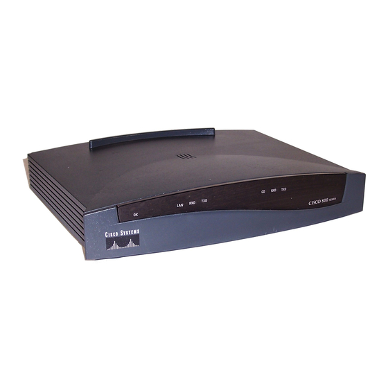
Page 21: Front Panel
Front Panel Front Panel Figure 1-1 describes the Cisco 805 front panel. Figure 1-1 Cisco 805 Front Panel LAN LEDs Indicate packets WAN LEDs are sent to or Indicate packets received from OK LED are sent to or Ethernet port. - Page 22 “Connecting an Ethernet Device” section in Chapter 2, “Installing the Cisco 805 Router.” Cisco 805 Router Hardware Installation Guide...
-
Page 23: Leds
LEDs LEDs Table 1-2 summarizes the function of each LED. All LEDs are on the router front panel except for the LINK LED, which is on the router back panel. Table 1-2 LED Functions Corresponding Port/Component Color Function Power Green On when power is supplied to the router and when the router completes the self-test procedure and begins operating. - Page 24 LEDs Cisco 805 Router Hardware Installation Guide...
-
Page 25: Installing The Cisco 805 Router
Before installing the router, read the following warnings: Only trained and qualified personnel should be allowed to install or Warning replace this equipment. Read the installation instructions before you connect the system to its Warning power source. Installing the Cisco 805 Router 2-1... - Page 26 SELV circuits, and WAN ports contain TNV circuits. Some LAN and WAN ports both use RJ-45 connectors. Use caution when connecting cables. Figure 2-1 shows the Cisco 805 router ports that include SELV circuits. For a definition of SELV and TNV, see “Terms and Acronyms” in “About this Guide.”...
-
Page 27: Esd
If cables are connected at one end only, do not touch the exposed pins at the unconnected end of the cable. This device is intended for use in residential and commercial environments only. Note Installing the Cisco 805 Router 2-3... -
Page 28: Required Equipment
3/4-inch (M3.5 x 20 mm) screws. If the wall to which you plan to mount your router is drywall, you must also provide two hollow wall-anchors (1/8 inch with 5/16-inch drill bit or M3 with 8-mm drill bit) to secure the screws. Cisco 805 Router Hardware Installation Guide... -
Page 29: Unpacking The Box
• Ethernet cable (yellow) • Product documentation A serial cable does not ship with the router. For information on selecting and Note ordering the serial cable, refer to Appendix A, “Selecting a Serial Cable.” Installing the Cisco 805 Router 2-5... -
Page 30: Installing The Router
Table 2-1 lists the Ethernet devices you can connect to the router with the yellow Ethernet cable and the appropriate settings of the router HUB/NO HUB button and the hub equivalent of the HUB/NO HUB button. The default setting of the router HUB/NO HUB button is HUB (in). Cisco 805 Router Hardware Installation Guide... -
Page 31: Connecting A Hub
NO HUB (out) – Hub vendors choose different names for the button controlling cable selection. This table uses the Cisco 1528 Micro Hub 10/100 with an MDI/MDI-X button as an example. Determine the button name and setting for your particular hub. Refer to your hub documentation for details. -
Page 32: Connecting A Server, Pc, Or Workstation
Make sure that the device has a 10- or 10/100-Mbps NIC. • Refer to Table 2-1 to determine how to set the router HUB/NO HUB button. Follow the steps in Figure 2-4 to connect a server, PC, or workstation. Cisco 805 Router Hardware Installation Guide... - Page 33 LI NK C O N S O 10 B A S SE R IA L 2. Connect yellow cable to yellow Ethernet port. 3. Connect other end of cable to server, PC, or workstation. Installing the Cisco 805 Router 2-9...
-
Page 34: Connecting A Serial Device
The Cisco 805 router does not support the Australian IUT requirement, Caution which specifies that the router must communicate for 1/2 hour after a power failure. If a power failure occurs, the Cisco 805 router stops communicating with other devices. 2-10... - Page 35 C O N S O 10 B A S SE R IA L 1. Connect appropriate end of serial cable to dark blue serial port. Modem or CSU/DSU 2. Connect other end of cable to modem or CSU/DSU. Installing the Cisco 805 Router 2-11...
-
Page 36: Connecting A Terminal Or Pc
1. Connect light blue cable to light blue Console port. 3. Connect DB-9 or DB-25 connector to terminal or PC. DB-X-to-RJ-45 adapter 2. Connect other end of cable to either DB-9-to-RJ-45 adapter or DB-25-to-RJ-45 adapter. 2-12 Cisco 805 Router Hardware Installation Guide... -
Page 37: Connecting The Power Supply
SE R IA L 5. Press power switch 2. Connect power to ON ( ). supply cable. Desktop power supply 4. Connect other end of power cord to 3. Connect power cord electrical outlet. to power supply. Installing the Cisco 805 Router 2-13... -
Page 38: Mounting The Router
(1/8 inch with 5/16-inch drill bit or M3 with 8-mm drill bit) to secure the screws. If the screws are not properly anchored, the strain of the network cable connections could pull the router from the wall. 2-14 Cisco 805 Router Hardware Installation Guide... - Page 39 To mount the router, follow the steps in Figure 2-9. The last page of this manual provides a template for measuring the distance between the screws. Installing the Cisco 805 Router 2-15...
- Page 40 Wall-mount Front screw panel 9 . 3 i n . Wall Mounting Wall-mount brackets screw in. (0.32 cm) Wall Screw Maximum distance 6 ft (18 m) 3. Place power supply on horizontal surface. 2-16 Cisco 805 Router Hardware Installation Guide...
-
Page 41: Verifying Installation
Cisco strongly recommends that you use the Cisco 805 Fast Step software. Use the Cisco 805 Fast Step CD-ROM that ships with the Cisco 805 router and Cisco 805 Fast Step online help. If you decide to use the command-line interface (CLI) to configure the software, refer to the Cisco 805 Router Software Configuration Guide. - Page 42 Where to Go Next 2-18 Cisco 805 Router Hardware Installation Guide...
-
Page 43: Chapter 3 Troubleshooting
C H A P T E R Troubleshooting This chapter describes problems that could occur with the Cisco 805 router hardware, reasons for the problems, and steps to solve the problems. The problems are grouped into the following states: •... -
Page 44: Problems During First Startup
Ethernet device. problem: To make sure you have cabled the device correctly, refer to (The LINK LED on — Improperly Figure 2-3 or Figure 2-4 in Chapter 2, “Installing the Cisco the back panel is connected cable. 805 Router.” off.) —... -
Page 45: Problems After Router Is Running
• Improperly connected • To make sure that you have cabled properly, refer to Figure 2-5 cable. in Chapter 2, “Installing the Cisco 805 Router.” • Make sure the connectors at both ends of the cable are securely seated. • Improperly functioning •... - Page 46 • Make sure the cable is not physically damaged. — Damaged cable. If it is damaged, order another cable from Cisco or replace it with a similar cable. • CSU/DSU configura- • Check CSU/DSU configuration. If necessary,...
-
Page 47: Before You Call Your Cisco Reseller
Before You Call Your Cisco Reseller Before You Call Your Cisco Reseller Some of the solutions in this chapter instruct you to contact your Cisco reseller. Before you do so, have the following information ready: • Router model and serial number (on the back panel) •... - Page 48 Before You Call Your Cisco Reseller Cisco 805 Router Hardware Installation Guide...
-
Page 49: Appendix A Selecting A Serial Cable
What signaling standard does the serial connector on the device require? • Is the serial connector on the device male or female? The Cisco 805 Router serial interface is a basic serial interface. Note The following sections provide information to help you answer these questions. -
Page 50: Dte Or Dce
Table A-1. This table summarizes serial devices that can be connected to the router serial port and whether the device is considered a DTE or DCE device. The Cisco 805 router is a DTE device by default. Table A-2 describes the type of cable needed to connect a DTE or DCE device to your router. - Page 51 DTE or DCE Table A-2 Cable Type Needed to Connect Serial Devices Serial Device Type Cable Type Needed Selecting a Serial Cable A-3...
-
Page 52: Signaling Standards
A DTE device typically has a male connector, while a DCE device typically has a female connector. Examine the serial connector on your serial device to determine its gender. Cisco 805 Router Hardware Installation Guide... -
Page 53: Serial Connection Example
Serial Connection Example Serial Connection Example Figure A-1 shows a typical serial connection for the Cisco 805 router. In this example, the router, which is a DTE device, is connected to a CSU/DSU or modem, which are DCE devices. Figure A-1... -
Page 54: Serial Cable Part Numbers
Serial Cable Part Numbers Serial Cable Part Numbers Table A-3 summarizes serial cables that you can order from Cisco. Table A-3 Cisco Serial Cables Mode Signaling Gender Part Number EIA/TIA-232 Female CAB-SS-232FC EIA/TIA-232 Male CAB-SS-232MT EIA/TIA-449 Female CAB-SS-449FC EIA/TIA-449 Male... -
Page 55: Appendix B Technical Specifications
A P P E N D I X Technical Specifications Table B-1 outlines the technical specifications for the Cisco 805 router. Table B-1 Technical Specifications Description Design Specification Physical Dimensions Dimensions (H x W x D) 2.0 x 9.7 x 8.3 in. (5.1 x 24.6 x 21.1 cm) Weight (does not include desktop power supply) 1.5 lbs (0.66 kg) - Page 56 For information on regulatory compliance, refer to the Regulatory Compliance and Safety Information for the Cisco 805 Router document that shipped with your router. Ultimate disposal of this product should be handled according to all Warning national laws and regulations.
-
Page 57: Appendix C Connector And Cable Specifications
A P P E N D I X Connector and Cable Specifications This appendix provides connector and cable specifications for the Cisco 805 router. Connector Specifications This section provides pinouts for the following connectors: • Ethernet—Table C-1 • Console—Table C-2 •... - Page 58 Ethernet Connector Pinouts (RJ-45) (continued) Function 1 Function 2 Unused Unused Unused Unused Table C-2 Console Connector Pinouts (RJ-45) Function Request to send Data terminal ready Transmit Ground Ground Receive Data set ready Clear to send Cisco 805 Router Hardware Installation Guide...
- Page 59 Connector Specifications Table C-3 Serial Connector Pinouts (SCSI) Function Function O_Transmit/receive+ O_Transmit/receive- O_Transmit clock echo/receive clock+ O_Transmit clock echo/receive clock- B_Transmit clock/transmit clock+ B_Transmit clock/transmit clock- I_Receive clock/transmit clock echo+ I_Receive clock/transmit clock echo- I_Receive/transmit+ I_Receive/transmit- B_Data carrier detect/data carrier detect+ B_Data carrier detect/data carrier detect- O_Data terminal ready/data set ready+ O_Data terminal ready/data set ready-...
-
Page 60: Cable Specifications
Table C-5 provides Ethernet cable specifications. Table C-5 Ethernet Cable Specifications Type Category Shielding 10BaseT 3, 4, or 5 Unshielded twisted-pair (UTP) The maximum distance for the Ethernet cable is 328 ft (100 m). Cisco 805 Router Hardware Installation Guide... -
Page 61: I N D E X
1-3, 2-2 selecting cabling pinouts specifications caution statements, defined CD LED 1-3, 1-5, 2-17 Fast Step software, Cisco 805 2-17 CD RXD LED 1-3, 1-5 features summary CD TXD LED 1-3, 1-5 flash memory, adding Cisco 805 Fast Step software... - Page 62 OK LED 1-3, 1-5, 2-17 ordering serial cable table mounting 2-14 temperature specifications terminal, connecting 2-12 panel, front, illustrated troubleshooting PC, connecting 2-8, 2-12 physical specifications port connector pinouts Index 2 Cisco 805 Router Hardware Installation Guide...
- Page 63 unpacking the router 2-5, ?? to 2-5 voltage specifications wall brackets illustrated 2-15 wall mounting 2-14, 2-16 warning statements, defined warnings, installation workstation, connecting Index 3...
- Page 64 Index 4 Cisco 805 Router Hardware Installation Guide...