
Related Manuals for Asus E1816


Summary of Contents for Asus E1816
- Page 1 Centralized Network Management GigaX Smart Switch Management Software User’s Manual E1816 / Oct 2004...
-
Page 2: Copyright Information
Circumstances may arise where because of a default on ASUS’ part or other liability, you are entitled to recover damages from ASUS. In each such instance, regardless of the basis on which you are entitled to claim damages from ASUS, ASUS is liable for no more than damages for bodily injury (including death) and damage to real property and tangible per- sonal property;... -
Page 3: Product Contact Information
Technical Support General Support: +1-502-995-0883 Notebook (Tel): +1-510-739-3777 x5110 Support Email: notebooktsd@asus.com Support Fax: +1-502-933-8713 ASUS COMPUTER GmbH (Germany & Austria) Company Address: Harkort Str. 25, D-40880 Ratingen, Germany General Telephone: +49-2102-95990 General Fax: +49-2102-959911 Web Site Address: www.asuscom.de Online Contact: www.asuscom.de/sales... -
Page 4: Table Of Contents
Table of Contents Copyright Information Limitation of Liability ..............2 Product Contact Information 1 Introduction 1.2 Using this Document ............5 2 Getting to Know the GigaX Smart Switch 2.1 Parts List ................6 2.2 GigaX Smart Switch Features ........... 6 2.3 Technical Specifications ............ -
Page 5: Introduction
Congratulations on your purchase of the ASUS GigaX Smart Switch. You can now manage your LAN (Local Area Network) through a friendly and powerful user interface, the ASUS CNM. The ASUS CNM runs on Windows OS. Please refer to the CNM installation guide for CM installation details. -
Page 6: Getting To Know The Gigax Smart Switch
Getting to Know the GigaX Smart Switch 2.1 Parts List In addition to this document, the switch should come with the following: • GigaX Smart Switch • AC Power cord • Rack installation kit (2 brackets with 6 screws (M3 x 6L)) •... -
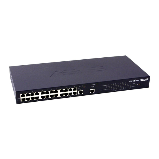
Page 7: Front Panel
2.4 Front Panel The front panel contains LED indicators that show the status of the unit. Label Color Light Function POWER Green The switch is powered on and operate normally The switch is powered off 10/100 ports from 1 to 24 STATUS / SPEED Green Ethernet link is established in 100 Mbps... -
Page 8: Quick Start Guide
Part 3 shows you how to configure basic settings on the GigaX Smart Switch. This Quick Start Guide assumes that you have installed ASUS CNM in a Windows PC. Both the switch and the PC are located in the same network. For CNM installation, please refer to the CNM installation guide. -
Page 9: Part 2 -Start The Switch
(with CNM installed), and to the network. 3.2.1 Step 1. Connect to the PC with CNM Installed The switch can be managed through the ASUS CNM software that is running on a Windows OS computer. Please refer to the CNM installation guide for details. -
Page 10: Management From Cnm
LED Indicators This LED Should be POWER Solid green to indicate that the device is turned on. If this light is not on, check if the power cord is attached to the switch and if it is plugged into a power source. - Page 11 Figure 3.2 CNM Outlook (GigaX 1024P) Figure 3.2.1 CNM Outlook (GigaX 1024I) GigaX Smart Switch Centralized Network Management...
- Page 12 3. Select the proper NIC at the same network with the switch, then click on the Discovery icon in the tool bar. After the discovery is done, the left frame of the window will show the MAC addresses of the switches discovered by the CNM as shown below.
- Page 13 4. Select the switch you want to manage by clicking on the MAC address, then you can start to configure the switch by CNM. 5. If the CNM cannot discover the switch you want to manage, please repeat step 1 to 4 again. Note: The switch must be powered on and connect to your network before starting the CNM.
-
Page 14: Management Functions
Management Functions ASUS provide a Centralized Network Management (CNM) software to allow users manage the switch in your network. The program is designed to work best with Microsoft Windows operation system. 4.1 Start CNM Program 1. Install CNM in a computer running Windows OS. Refer to CNM installation guide for detail installation steps. -
Page 15: Functional Layout
4.2 Functional Layout The CNM window consists of three separate frames. The top frame has switch logo and front panel as shown below. This frame remains on the top of the browser window all the times and updates the LED status periodically. The LED definition has been described in Table 3.1. - Page 16 The left frame, a topology frame as shown in Figure 4.3, contains all the NICs in the manage station. Each NIC has a tree view to show the switches that are discovered by CNM. You can click on any of these to display a specific configuration of the switch.
-
Page 17: General Settings For Cnm
4.3 General Settings for CNM There are menu bar and tool bar on the top of the CNM window. They offer general settings for CNM. • The Topology item provides the general network discovery, manually add or delete switches, and load or save the current discovered topology. •... - Page 18 5. Add Switch: add a switch to the topology tree manually. A window will show for this purpose as shown below. Select the network adapter you want the switch to attach to, give the switch MAC and name, and an authentication key as the password if you don’t use the default one (2379), then click OK to finish the action.
- Page 19 6. Remove Switch: you can remove any switch in the topology list manually through this function. It pops out a switch list and check those switches you want to remove. Please refer to Figure 4.7 for the switch list window. Figure 4.7 Remove Switch 4.3.2 Setup Figure 4.8.
-
Page 20: Switch Topology
4.4 Switch Topology The switch topology frame is on the left part of the CNM window. It shows the discovered switches and the relationship among them. Each presents a NIC interface. The interface name and MAC address is shown after the. The switch topology shows the relationship among the switches in a tree view. - Page 21 4.4.2 Switch Add and Removal Discovery action will create the topology tree by all the discovered switches. The default password will be used in the discovery process. Sometimes you may have a switch with another password that is different from the default one. In this case, the switch cannot be discovered by the default password.
- Page 22 Once a switch is added to the topology tree, you can find it in the corresponding place. You have to left click the switch symbol to switch the current status/ configuration window from other switch to this switch. If the communication is good, you can see the linking status window on the right frame of the CNM window, and the topology tree will display the switch symbol in a correct place to show the relationship.
-
Page 23: Switch Setup
4.5 Switch Setup Before using the configuration windows, it is better to know following buttons or icons because they are used throughout the setup. The following table describes the function for each button or icon. Table 4.1 2 Description of Commonly Used Buttons Buttons Function Apply to the selected switch... -
Page 24: System
4.6 System The system menu provides reboot, link status, and change password. 4.6.1 Reboot Hardware and software reset functions are provided. Hardware reset returns the system to its initial state just like power on hardware reset. Note: Hardware reset will clear all configuration settings. Software reset will return the system to the initial state and start port link negotiations, but the MAC table, VLAN table data, and configuration settings will not be erased. - Page 25 4.6.2 Link Status Link status table shows the port information including speed, duplex mode and flow control. Click on the Reload button will get the update information. Figure 4.14 shows the status table. Figure 4.14 Link Status (GigaX 1024P) Figure 4.14.1 Link Status (GigaX 1024I) GigaX Smart Switch Centralized Network Management...
- Page 26 4.6.3 Change Password A valid password consists of 4 digits, from 0 to 9, and a to f. The authenticator does not check upper case or lower case. For example, password “12ab” is treated as “12AB”. Once the password gets changed, CNM will use the password to retrieve the information about the switch.
- Page 27 4.6.4 Load You can load configuration from the switch or the local file as shown below. This action will update the current configuration in the CNM. If you want to keep the current configuration, please refer to section 4.6.5. Figure 4.15 Load (GigaX 1024P) Figure 4.15.1 Load (GigaX 1024I) GigaX Smart Switch Centralized Network Management...
- Page 28 4.6.5 Save Save all the configurations to a local file for future reference. Once you create a configuration file in CNM, you can use it to apply to the other switches to save your time. It is also a backup file for configuration. It is recommended to have a good file name to identify that the configuration is for the certain switch(es).
- Page 29 4.6.6 Apply and Save It applies all the current settings in CNM to the switch and save them in the switch permanently. It is recommended to back up the existed switch configurations before applying a new configuration to the switch. Figure 4.17 Apply Configuration (GigaX 1024P) Figure 4.17.1 Apply Configuration (GigaX 1024I) GigaX Smart Switch Centralized Network Management...
-
Page 30: Configuration
4.7 Configuration The Configuration menu provides the configuration for all the functions that the switch can supports, like physical interface, link aggregation, bandwidth control, traffic control, VLAN, IGMP snooping and QoS. To keep all the new configurations and save the bandwidth for communications, each configuration page will not retrieve information from switch until you click the Reload button. - Page 31 Figure 4.18.1 Physical Interface (GigaX 1024I) Above shows the configuration for each port. Select the ports you want to configure or reload information from the switch by clicking on the check boxes in front of the ports, then click on Config to set the configuration for the ports, or click on Reload to retrieve configuration from the switch, or click on Apply to apply the new settings to the switch.
- Page 32 4.7.2 Link Aggregation Figure 4.19 Link Aggregation (GigaX 1024P) Figure 4.19.1 Link Aggregation (GigaX 1024I) GigaX Smart Switch Centralized Network Management...
- Page 33 Link aggregation creates new virtual links with more bandwidth. For example, port 1 and 2 can work together as one link to another device. The new virtual link has 200Mbps bandwidth. The switch provides 8 groups (GigaX 1024P) or 7 groups (GigaX 1024I) of link aggregations shown above. Click on the Reload button to retrieve the configuration from switch.
- Page 34 Figure 4.20.1 Bandwidth Configuration (GigaX 1024I) GigaX Smart Switch provides TX/RX bandwidth control for each port. Please reload the configuration before you start to set up new configuration. The page is shown above. Select the ports you want to configure, then select proper bandwidth for TX/RX directions.
-
Page 35: Vlan Setup
4.7.4 Traffic Control Traffic control is to set the following items 1. Broadcast storm filtering control: if enabled, each port start to drop broadcast packets after a continuous received broadcast packets count up to 64. It will be back to normal if no more broadcast packet is received in 800ms or any non- broadcast packet is received. - Page 36 Figure 4.21 VLAN (GigaX 1024P) Figure 4.21.1 VLAN (GigaX 1024I) GigaX Smart Switch Centralized Network Management...
- Page 37 All VLAN behavior will be influenced by VLAN control option. Click Control Option and a window will appear as shown as below. Enable or disable these options carefully, these options are global setting for VLAN Figure 4.22 VLAN Control Options 7.
- Page 38 4.7.6 IGMP Snooping Enable the IGMP snooping will let the switch learn the multicast router port and group address member ports into the multicast address table. The table is combined with L2 MAC table, so the maximum entry is 8K. The valid port member will auto aging out after about 5 minute idle.
- Page 39 4.7.7 QoS Setup The system support 2 level priority queues. The queue service rate is based on the packet-based Weighted Round Robin algorithm. The ratio can be set as 4:1, 8:1, 16:1, or strictly high priority first. The port-based priority is to decide the packet priority by the receiving ports. You can select the high priority ports from the switch graphic.
- Page 40 Figure 4.24.1 QoS Setup (GigaX 1024I) GigaX Smart Switch Centralized Network Management...
-
Page 41: Statistics
4.8 Statistics Statistics offer Port Traffic, Traffic History and Comparison charts. The switch has 3 counters for 8 kinds of statistics. So you cannot see all the statistics at the same time. That is, the old statistics data will be gone if you start to use the counter for another statistics. - Page 42 4.8.2 Traffic History Select the statistics item, ports and colors you want to see in the chart, then press the Draw Traffic Chart button to start the drawing. The chart will be auto updated in the time interval you set in Setup menu. Refer to 4.3.2 for time interval setup.
- Page 43 4.8.3 Comparison Select the statistics item to do comparison for port 1 to 26 (ports 25-26 on GigaX 1024P only). Press the Draw Traffic Chart button to start the drawing. The chart will be auto updated in the time interval you set in Setup menu. Figure 4.27 Port Comparison (GigaX 1024P) Figure 4.27.1 Port Comparison (GigaX 1024I) GigaX Smart Switch Centralized Network Management...
- Page 44 GigaX Smart Switch Centralized Network Management...