Motorola MC3000R - Win CE 5.0 Core 312 MHz Integration Manual
Mc3000 series integration guide
Hide thumbs
Also See for MC3000R - Win CE 5.0 Core 312 MHz:
- User manual (146 pages) ,
- Quick start manual (2 pages) ,
- Quick start manual (2 pages)
Table of Contents
Advertisement
Quick Links
Download this manual
See also:
User Manual
Advertisement
Table of Contents
Troubleshooting

Related Manuals for Motorola MC3000R - Win CE 5.0 Core 312 MHz


Summary of Contents for Motorola MC3000R - Win CE 5.0 Core 312 MHz
- Page 1 MC3000 Integrator Guide...
- Page 3 MC3000 Mobile Computer Integrator Guide 72E-68900-05 Revision A October 2008...
-
Page 4: Patents
Motorola. No right to copy a licensed program in whole or in part is granted, except as permitted under copyright law. The user shall not modify, merge, or incorporate any form or portion of a licensed program with other program material, create a derivative work from a licensed program, or use a licensed program in a network without written permission from Motorola. -
Page 5: Revision History
SMDK information. -03 Rev A March 2007 Add 20-key mechanical keypad and Fusion 2.5 information. -04 Rev A August 2007 Motorola re-branding. Operating system update: OEM Version 05.26.0000. -05 Rev A October 2008 Add Windows Mobile 6.1 configurations. - Page 6 MC3000 Integrator Guide...
-
Page 7: Table Of Contents
Table of Contents Patents..............................ii Revision History............................ iii About This Guide Introduction ............................xi Documentation Set ......................... xi Configurations............................xii Software Versions........................... xii Chapter Descriptions ..........................xv Notational Conventions......................... xv Related Documents and Software ......................xvi Service Information..........................xvi Chapter 1: Getting Started Introduction ............................ - Page 8 MC3000 Integrator Guide Flash Storage ............................1-17 Launching Applications ........................1-18 Chapter 2: Accessories Introduction ............................2-1 Cradles ............................2-1 Spare Battery Chargers ......................... 2-1 Cables ............................2-1 SD Card ............................2-1 Single Slot Serial/USB Cradle ......................2-2 Setup .............................. 2-3 Battery Charging ..........................
- Page 9 Table of Contents Serial Communication Setup ......................2-30 Setting Up a Connection on the Mobile Computer (Windows Mobile 6.1) ........2-30 USB Connection Setup ........................2-34 Cradle/Cable Setup ........................2-36 USB Host Communication Setup ......................2-37 Chapter 3: ActiveSync Introduction ............................3-1 Installing ActiveSync ..........................
- Page 10 viii MC3000 Integrator Guide Digital Signatures ........................... 5-1 Device Management Security ......................5-3 Remote API Security ........................5-3 Packaging ............................5-4 Deployment ............................5-4 Installation Using ActiveSync ......................5-4 Installation Using AirBEAM ......................5-4 MSP 3.X ............................5-4 Image Update ..........................5-5 Creating a Splash Screen ......................
- Page 11 Table of Contents Wireless Status Application ......................... 6-27 Signal Strength Window ......................... 6-28 Current Profile Window ........................6-30 IPv4 Status Window ........................6-31 Wireless Log Window ........................6-32 Versions Window ........................... 6-33 Wireless Diagnostics Application ......................6-34 ICMP Ping Window ........................6-34 Trace Route Window ........................
- Page 12 MC3000 Integrator Guide Appendix A: Technical Specifications Mobile Computer and Accessory Technical Specifications ..............A-1 Mobile Computer Pin-Outs ........................A-4 Laser Decode Ranges ........................A-6 Imager Decode Ranges ......................... A-8 Appendix B: Internet Explorer Kiosk Mode Introduction ............................B-1 Glossary Index...
-
Page 13: About This Guide
Microsoft Application Guide for Windows Mobile 6 User Guide - describes how to use Microsoft developed applications. • Application Guide for Motorola Enterprise Mobility Devices - describes how to use Motorola developed applications. • MC3000 User Guide - describes how to use the MC3000 mobile computer. -
Page 14: Configurations
MC3000 Integrator Guide Configurations This guide covers the following configurations: Data Operating Configuration Radios Display Memory Keypads Capture System MC3000R None Color or 32 MB RAM/ 1D laser Windows 28, 38 or 48 monochrome 64 MB Flash or scanner in CE 5.0 Core or 64 MB RAM/ rotating... - Page 15 About This Guide xiii The second line lists the operating system version and the build number. The last part of the build number represents the AKU number. For example, Build 119581.1.1.1 indicates that the device is running AKU version 1.1.1. OEM Version on Windows Mobile 6.1 Devices To determine the OEM software version on a Windows Mobile 6.1 device: >...
- Page 16 MC3000 Integrator Guide BTExplorer Software To determine the BTExplorer software version on a Windows Mobile 6.1 or Windows CE 5.0 device: icon > > > BTExplorer Show BTExplorer File About Fusion Software To determine the Fusion software version on a Windows Mobile 6.1 or Windows CE 5.0 device: icon >...
-
Page 17: Chapter Descriptions
Notational Conventions The following conventions are used in this document: • The term “mobile computer” refers to the Motorola MC3000. • Italics are used to highlight the following: • Chapters and sections in this and related documents • Dialog box, window and screen names •... -
Page 18: Related Documents And Software
Software type and version number Motorola responds to calls by email, telephone or fax within the time limits set forth in support agreements. If your problem cannot be solved by Motorola Enterprise Mobility Support, you may need to return your equipment... - Page 19 About This Guide xvii shipment if the approved shipping container is not used. Shipping the units improperly can possibly void the warranty. If you purchased your Enterprise Mobility business product from a Motorola business partner, contact that business partner for support.
- Page 20 xviii MC3000 Integrator Guide...
-
Page 21: Chapter 1 Getting Started
• Standard Battery (lithium-polymer) • Extended Life Battery (lithium-ion) • Cable(s) • Power Supply • Cradles. Inspect the equipment for damage. If any equipment is missing or damaged, contact Motorola Enterprise Mobility Support immediately. See page xvi for contact information. -
Page 22: Accessories
Provides a soft, clip on holder and a shoulder strap for the mobile computer. Enterprise Mobility Developer Kit for C A development tool used to create native C and C++ applications for all Motorola mobile computers running the Microsoft Windows CE operating system. Available at: http://www.motorola.com/enterprisemobility/support. Device Configuration Package (DCP) -
Page 23: Parts
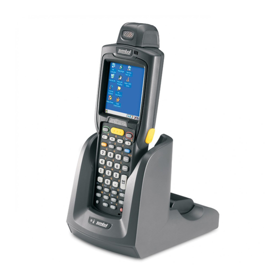
Getting Started 1 - 3 Parts There are three versions of the MC3000 mobile computers, the MC3000 1D/2D Imager (MC3000S or MC3090S), the MC3000 Laser with Rotating Scan Turret (MC3000R or MC3090R) and the MC3090 Gun (MC3090G). For more information on the Rotating Scan Turret, see Figure 1-3 on page 1-4. - Page 24 1 - 4 MC3000 Integrator Guide Headset Jack Scan Window (optional) Scan Window Headset Jack Strap/Door (optional) Assembly Screws Stylus Strap/Door Assembly Stylus Holder Latches MC3000R MC3000S MC3000 Imager (MC3000S) and MC3000 Laser (MC3000R) Mobile Computers (back view) Figure 1-2 Rotating Scan Turret The MC3000R mobile computer features a Rotating Scan Turret with three position stops.
- Page 25 Getting Started 1 - 5 Scan LED Charge LED Beeper Indicators Indicator (red/green) (amber) Indicator LED Bar Display Scan Button Keypad Power Scan LED Indicator (red/green) Trigger MC3090G Mobile Computer Figure 1-4...
-
Page 26: Mobile Computer Startup
1 - 6 MC3000 Integrator Guide Mobile Computer Startup To start using the mobile computer: • Install the main battery. • Charge the main battery and the backup battery. • Start the mobile computer. Install Main Battery If the main battery is charged, the mobile computer can be used immediately. If the main battery is not charged, see Battery Charging on page 1-8. - Page 27 Getting Started 1 - 7 Latches Hand Strap Battery Clip Battery Slot Battery Strap/Door Assembly Main Battery Installation Figure 1-5 Hand Strap Latches 0.5 in. (12.7 mm) Strap/Door Assembly Battery Strap/Door Assembly Main Battery Installation (MC3090G) Figure 1-6...
-
Page 28: Battery Charging
1 - 8 MC3000 Integrator Guide Battery Charging CAUTION Ensure that you follow the guidelines for battery safety described in Battery Safety Guidelines on page 8-1. Use the mobile computer cradles, cables and spare battery chargers to charge the mobile computer main battery. The main battery can be charged before insertion into the mobile computer or after it is installed. -
Page 29: Spare Battery Charging
Getting Started 1 - 9 The mobile computer starts to charge automatically. The amber Charge LED Indicator indicates the charge status. See Table 1-2 on page 1-9 for charging indications. To charge the mobile computer using the cables: Connect the MC3000 Communication/Charge Cable to the appropriate power source and connect to the mobile computer. -
Page 30: Starting The Mobile Computer
1 - 10 MC3000 Integrator Guide Starting the Mobile Computer When the mobile computer is powered on for the first time, it initializes. The screen appears for a short splash period of time, followed by the screen. Calibration Splash Screen Figure 1-7 After the calibration procedure is performed the factory default settings launch the . -
Page 31: Resetting The Mobile Computer
These sample/demo applications are intended to be used by application developers as application development examples. These applications were not developed to support end users. Refer to the Application Guide for Motorola Enterprise Mobility Devices for information about the applications. -
Page 32: Windows Mobile 6.1 Devices
1 - 12 MC3000 Integrator Guide Performing a Cold Boot A cold boot restarts the mobile computer and erases all user stored records and entries from RAM. Never perform a cold boot unless a warm boot does not solve the problem. CAUTION Cold boot resets the mobile computer, to the default settings. -
Page 33: Waking The Mobile Computer
Getting Started 1 - 13 Waking the Mobile Computer The wakeup conditions define what actions wake up the mobile computer after it has gone into suspend mode. The mobile computer can go into suspend mode by either pressing the Power button or automatically by Control Panel time-out settings. - Page 34 1 - 14 MC3000 Integrator Guide Strap/Door Hand Strap Latches Assembly Battery Battery Clip Main Battery Removal (MC3000S/R) Figure 1-10 Latches Strap/Door Assembly 0.5 in. (12.7 mm) Battery Pull Tab Battery with Pull Tab Battery without Pull Tab Main Battery Removal (MC3090G) Figure 1-11...
-
Page 35: Strap/Door Assembly Removal And Replacement
Getting Started 1 - 15 Strap/Door Assembly Removal and Replacement The Strap/Door Assembly consists of a hand strap and the battery door. There are two versions of this assembly, one for the Standard Battery and one for the Extended Life Battery. Before removing the Strap/Door Assembly, press the red button to turn off the screen and set the mobile computer to suspend mode. -
Page 36: Strap/Door Assembly Removal And Replacement (Mc3090G)
1 - 16 MC3000 Integrator Guide Strap/Door Assembly Removal and Replacement (MC3090G) The Strap/Door Assembly consists of a hand strap and the battery door. Before removing the Strap/Door Assembly, press the red button to turn off the screen and set the mobile computer to suspend mode. Power To remove the Strap/Door Assembly: Slip the button through the loop. -
Page 37: File System Directory Structure
Getting Started 1 - 17 File System Directory Structure The mobile computer directory structure displays all of the file folders. The pre-installed folders are in flash file system memory and optional removable storage devices (SD storage cards). Mobile Computer Directory Structure Figure 1-14 •... -
Page 38: Launching Applications
1 - 18 MC3000 Integrator Guide Launching Applications folder is used to launch programs automatically when the mobile computer is powered on Application/Startup or after a warm or cold boot. NOTE The Windows/Startup folder is not supported. There are two ways to launch programs automatically: Place the executable in the folder (located in the folder). -
Page 39: Chapter 2 Accessories
Chapter 2 Accessories Introduction The MC3000 accessories provide a variety of product support capabilities. Accessories include cradles, cables, spare battery chargers and SD cards. Cradles • Single Slot Serial/USB cradle charges the mobile computer main battery and/or a spare battery. It also synchronizes the mobile computer with a host computer through either a serial or a USB connection. -
Page 40: Single Slot Serial/Usb Cradle
For communication setup procedures, see USB Connection Setup on page 2-34. CAUTION Use only a Motorola approved power supply output rated 12 VDC and minimum 3.3 A. Use of an alternative power supply will void the product warranty and may cause product damage. See the... -
Page 41: Setup
To charge the mobile computer: Connect the Single Slot Serial/USB cradle to a Motorola approved power source. Slide the mobile computer into the mobile computer slot. The amber Charge LED Indicator indicates the mobile computer battery charging status. The Standard Battery charges in less than four hours and the Extended Life Battery charges in less than six hours. -
Page 42: Led Charge Indications
When charging is complete, remove the mobile computer from the mobile computer slot. To charge a spare battery: Connect the Single Slot Serial/USB cradle to a Motorola approved power source. Insert the spare battery into the spare battery charging slot, bottom first, and pivot the top of the battery down onto the contact pins. -
Page 43: Communication Setup
Accessories 2 - 5 LED Charging Status Indicators Table 2-1 Indication Mobile Computer Charging (LED on mobile computer) Mobile computer not placed correctly in the cradle; cable not connected correctly; charger is not powered. Fast Blinking Amber Error in charging; check placement of mobile computer. Slow Blinking Amber Mobile computer is charging. -
Page 44: Four Slot Charge Only Cradle
Simultaneously charges up to four mobile computers. CAUTION Use only a Motorola approved power supply output rated 12 VDC and minimum 9 A. Use of an alternative power supply will void the product warranty and may cause product damage. See the MC3000 User Guide for the power supply regulatory compliance statement. -
Page 45: Power Led
Accessories 2 - 7 Charge LED Indicator (amber) Scan/Charge Indicator LED Bar Mobile Computer Slot Power LED Four Slot Charge Only Cradle Figure 2-4 The mobile computer amber Charge LED Indicator indicates the mobile computer battery charging status. The Standard Battery usually charges in less than four hours and the Extended Life Battery usually charges in less than six hours. -
Page 46: Four Slot Ethernet Cradle
Slot Serial/USB cradle. CAUTION Use only a Motorola approved power supply output rated 12 VDC and minimum 9 A. Use of an alternative power supply will void the product warranty and may cause product damage. See the MC3000 User Guide for the power supply regulatory compliance statement. -
Page 47: Ethernet Cradle Drivers (Windows Mobile 6.1)
Accessories 2 - 9 Double-tap the icon to open the window. This window display the TCP/IP information for the mobile LANNDS1 computer. LAN Icon LANNDS1 Window Figure 2-6 Ethernet Cradle Drivers (Windows Mobile 6.1) The MC3000 includes Ethernet cradle drivers that initiate automatically when you place the MC3000 in a properly connected Four Slot Ethernet cradle. -
Page 48: Charging And Communication
2 - 10 MC3000 Integrator Guide • Use server-assigned IP address • . Enter the IP address, Subnet mask, and Default gateway, as needed. Use specific IP address Tap the tab. Name Servers Name Servers Tab Figure 2-9 Enter the appropriate DNS, Alt DNS, WINS, and Alt WINS server addresses. Tap ok. -
Page 49: Led Charge Indications
Accessories 2 - 11 LED Charge Indications The charge LED shows the status of the battery charging in the mobile computer. The Standard Battery usually charges in less than four hours and the Extended Life Battery usually charges in less than six hours. See Table 2-1 on page 2-5 for charging status indications. - Page 50 2 - 12 MC3000 Integrator Guide Table 2-2 shows allocated bandwidth (based on 100 Mbps) for the number of daisychained cradles, with each mobile computer attempting transmission at the maximum data rate. Daisychaining Bandwidth Table 2-2 Daisychained Ethernet Bandwidth Allocation For Each Bandwidth Allocation For Each Cradles Ethernet Cradle (bits/sec)
-
Page 51: Wall Mount Bracket
Accessories 2 - 13 Wall Mount Bracket Use the optional Wall Mount Bracket to mount a four slot cradle directly to a wall. To attach the Wall Mount Bracket: Use the Wall Mount Bracket as a template and mark the locations of the four mounting screws. NOTE Use fasteners appropriate for the type of wall and the Wall Mount Bracket, mounting slots. - Page 52 2 - 14 MC3000 Integrator Guide Mounting Screws Four Slot Cradle Bottom Cradle Mounting Screws Figure 2-13 Align the Wall Mount Bracket mounting tabs with the mounting slots in the back of the four slot cradle. Slip the two mounting tabs into mounting slots. Swing the four slot cradle down onto the mounting bracket and align the mounting screws so that they fit into the screw slots.
- Page 53 Accessories 2 - 15 Mounting Screws Figure 2-15 Connect the power (see Figure 2-3 on page 2-6). The power supply should be located in the power supply well.
-
Page 54: Four Slot Spare Battery Charger
The Four Slot Spare Battery Charger simultaneously charges up to four spare batteries. CAUTION Use only a Motorola approved power supply output rated 12 VDC and minimum 3.3 A. Use of an alternative power supply will void the product warranty and may cause product damage. See the MC3000 User Guide for the power supply regulatory compliance statement. -
Page 55: Led Charge Indications
Accessories 2 - 17 Power Supply Battery Clip Spare Battery Charging Slot Spare Batteries Spare Battery Charging LEDs (4) Four Slot Spare Battery Charger Figure 2-17 Gently press down on the battery to ensure proper contact. The Standard Battery usually charges in less than four hours and the Extended Life Battery usually charges in less than six hours. -
Page 56: Cables
• USB Client Charge cable (standard-A connector and a barrel receptacle for power). Use only a Motorola approved power supply output rated 5.4 VDC and minimum 3 A. Use of an CAUTION alternative power supply will void the product warranty and may cause product damage. See the MC3000 User Guide for the power supply regulatory compliance statement. -
Page 57: Setup
The MC3000 Communication/Charge cables can charge the mobile computer battery and supply operating power. To charge the mobile computer battery: Connect the MC3000 Communication/Charge cable power input connector to the Motorola approved power source. Attach the bottom of the mobile computer to the MC3000 connector and gently press in until the snaps latch on the mobile computer. -
Page 58: Universal Battery Charger (Ubc) Adapter
UBC 2000, refer to the UBC 2000 Quick Reference Guide, p/n 70-33188-xx. CAUTION Use only a Motorola approved power supply output rated 15 VDC and minimum 1.5 A. Use of an alternative power supply will void the product warranty and may cause product damage. See the MC3000 User Guide for the power supply regulatory compliance statement. -
Page 59: Ubc Adapter Led Charge Indications
Accessories 2 - 21 Battery Battery Clip UBC Adapter Spare Battery Charging Slot UBC Adapter Battery Insertion Figure 2-21 Gently press down on the battery to ensure proper contact. The Standard Battery usually charges in less than four hours and the Extended Life Battery usually charges in less than six hours. See Table 2-3 for charging status indications. - Page 60 2 - 22 MC3000 Integrator Guide UBC Adapter Charge LED Status Indications Table 2-3 Indication Description STANDBY or Flashing-Yellow The battery was deeply discharged and is being trickle charged to bring the voltage up to the operating level. After operating level voltage is achieved, the battery charges normally.
-
Page 61: Secure Device Card (Windows Ce 5.0 Only)
Accessories 2 - 23 Secure Device Card (Windows CE 5.0 Only) NOTE SD Card is not supported on WIndows Mobile 6.1 devices. The Secure Device (SD) card provides secondary non-volatile storage (the flash memory is slower than RAM). The SD card holder is located under the battery. CAUTION Follow proper Electro-Static Discharge (ESD) precautions to avoid damaging the SD card. -
Page 62: Copy Files Onto The Sd Card
2 - 24 MC3000 Integrator Guide Copy Files onto the SD Card The SD card can be used to store files or programs used by the mobile computer. Files may be copied using an available file browser, or using ActiveSync. InkWiz is a provided tool that is being used as an example of how to access data on the SD card. -
Page 63: Delete A File From The Sd Card
Accessories 2 - 25 InkWiz, Paste File Figure 2-26 Delete a File From The SD Card InkWiz is a provided tool that can be used to delete data from the SD card. Tap the MSIMGSIZ.DAT file to highlight. > to delete the file from the Storage Card partition. The window appears. - Page 64 2 - 26 MC3000 Integrator Guide Windows Control Panel Figure 2-28 Double tap the icon to access the Window. Storage Manager Storage Properties CAUTION Do not select any other partitions for formatting. The DSK3: SD/MMC Card selection is the only entry that can be formatted.
- Page 65 Accessories 2 - 27 In the text box enter a partition name, and tap OK. The window appears. Name: Storage Properties Storage Properties Window Figure 2-31 window displays the new partition name in the box. The asterisk next to the Storage Properties Partitions: partition name, indicates that the partition is mounted.
- Page 66 2 - 28 MC3000 Integrator Guide Format Confirmation Window Figure 2-34 , the in progress window appears. Format Format In Progress Window Figure 2-35 in progress window completion bar indicates the status of the format. When the format is complete Format complete window appears with a message.
- Page 67 Accessories 2 - 29 Storage Properties Window Figure 2-38 , to exit the Storage Manager...
-
Page 68: Serial/Usb Communication
2 - 30 MC3000 Integrator Guide Serial/USB Communication This section provides information on installing the appropriate serial/USB communication software and setting up the appropriate accessory to enable serial/USB communication between the mobile computer and the host device. The mobile computer is capable of communicating with a number of hosts, including development computers, serial devices, printers, etc. - Page 69 Accessories 2 - 31 ActiveSync Window Figure 2-39 > . The window appears. Menu Connections Connections Connections Window Figure 2-40 Select the Synchronize all PCs using this connection: check box. Select the connection (e.g., serial COM port, Bluetooth, or USB) for synchronization from the drop-down list. The default connection for synchronization is USB.
- Page 70 2 - 32 MC3000 Integrator Guide NOTE Every mobile computer should have a unique device name. Never try to synchronize more than one mobile computer to the same name. In the ActiveSync window, select > . The window appears. File Connection Settings Connection Settings Connection Settings Window...
- Page 71 Accessories 2 - 33 PC Connection Properties Window Figure 2-43 Tap the button. Change Connection Select the connection type from the drop-down list. Change Connection Window Figure 2-44 to exit the window and tap to exit the window. Change Connection PC Connection Properties Ensure that ActiveSync was installed on the host computer and a partnership was created.
-
Page 72: Usb Connection Setup
2 - 34 MC3000 Integrator Guide Serial Connection Setting Figure 2-46 Tap OK to save any changes made. NOTE Every mobile computer should have a unique device name. Never try to synchronize more than one mobile computer to the same name. Connect the device to the host computer. - Page 73 Accessories 2 - 35 Select the connection type from the drop-down list. Change Connection Window Figure 2-48 to exit the window and tap to exit the window. Change Connection PC Connection Properties Ensure that ActiveSync was installed on the host computer and a partnership was created. See Setting Up an ActiveSync Connection on the Host Computer on page 3-3 for more information.
-
Page 74: Cradle/Cable Setup
2 - 36 MC3000 Integrator Guide NOTE Every mobile computer should have a unique device name. Never try to synchronize more than one mobile computer to the same name. Connect the device to the host computer. See Figure 2-1 on page 2-3 to set up a Single Slot Serial/USB cradle, or see Figure 2-19 on page 2-19... -
Page 75: Usb Host Communication Setup
Accessories 2 - 37 USB Host Communication Setup NOTE USB Host mode is only available on Windows Mobile 6.1 devices. The mobile computer can be configured as a USB host device for use with USB client devices. To configure the mobile computer as a USB host: >... - Page 76 2 - 38 MC3000 Integrator Guide...
-
Page 77: Chapter 3 Activesync
Chapter 3 ActiveSync Introduction To communicate with various host devices, install Microsoft ActiveSync (version 4.5 or higher) on the host computer. Use ActiveSync to synchronize information on the mobile computer with information on the host computer. Changes made on the mobile computer or host computer appear in both places after synchronization. NOTE When a mobile computer with Windows Mobile 6.1 is connected to a host computer and an ActiveSync connection is made, the WLAN and WWAN radios (if applicable) are disabled. -
Page 78: Mobile Computer Setup
3 - 2 MC3000 Integrator Guide Mobile Computer Setup NOTE Microsoft recommends installing ActiveSync on the host computer before connecting the mobile computer. The mobile computer can be set up to communicate either with a serial connection or a USB connection. Chapter 2, Accessories provides the accessory setup and cable connection information for use with the mobile computer. -
Page 79: Setting Up An Activesync Connection On The Host Computer
ActiveSync 3 - 3 Select the connection type from the drop-down list. to exit the window and tap to exit the window. Connections ActiveSync Proceed with installing ActiveSync on the host computer and setting up a partnership. Setting Up an ActiveSync Connection on the Host Computer To start ActiveSync: Select >... -
Page 80: Setting Up A Partnership With A Windows Ce 5.0 Device
3 - 4 MC3000 Integrator Guide Setting up a Partnership with a Windows CE 5.0 Device To set up a partnership with a Windows CE 5.0 device: If the window does not appear on the host computer, select > > Get Connected Start All Programs... - Page 81 .reg file and save it in the Flash File System, detailed information is provided in the EMDK Windows CE Help File for Motorola Mobile Computers. For more information about using ActiveSync, start ActiveSync on the host computer, then see ActiveSync Help.
-
Page 82: Synchronization With A Windows Mobile 6.1 Device
3 - 6 MC3000 Integrator Guide Synchronization with a Windows Mobile 6.1 Device NOTE When a mobile computer with Windows Mobile 6.1 is connected to a host computer and an ActiveSync connection is made, the WLAN and WWAN radios (if applicable) are disabled. This is a Microsoft security feature to prevent connection to two networks at the same time. - Page 83 ActiveSync 3 - 7 Synchronization Option Window Figure 3-11 Select the appropriate settings and click Next Wizard Complete Window Figure 3-12 Click Finish...
- Page 84 3 - 8 MC3000 Integrator Guide ActiveSync Connected Window Figure 3-13 During the first synchronization, information stored on the mobile computer is copied to the host computer. When the copy is complete and all data is synchronized, the mobile computer can be disconnect from the host computer. NOTE The first ActiveSync operation must be performed with a local, direct connection.
-
Page 85: Chapter 4: Application Deployment For Windows Ce
Device Configuration Package (DCP) for MC3000. The EMDK for C is a development tool used to create native C and C++ applications for all Motorola Enterprise Mobility mobile computers. It includes documentation, header files (.H), and library files (.LIB) for native code application development that targets Motorola value-add APIs. -
Page 86: Device Configuration Package
Device Configuration Package To download and install the DCP: Download the DCP from the Support Central web site: http://www.motorola.com/enterprisemobility/support. Select Mobile Computers. The Mobile Computer Products page displays. Select MC3000. The MC3000 Product page displays. On the MC3000 Product page, select the Device Configuration Package (DCP) for MC3000 from the Software Downloads section. -
Page 87: Platform Sdk
Windows CE .NET 5.0 Core platforms. To download and install the appropriate Platform SDK: Download the appropriate Platform SDK from the Support Central web site, http://www.motorola.com/enterprisemobility/support. Select Mobile Computers. The Mobile Computer Products page displays. Select MC3000. The MC3000 Product page displays. -
Page 88: Components
Microsoft Visual C++ v4.0 launches. Components The sample applications provide examples of how to interface with the Motorola API functions. To build a sample application, open the Samples folder from the Windows Start menu. Open the folder for the desired sample and then open the project file. -
Page 89: Installing Other Development Software
Software Updates Download updates to the EMDK for C from the Support Central web site at: http://www.motorola.com/enterprisemobility/support. Check this site periodically for important updates and new software versions. Deployment With the appropriate accessory, software, and connection, the mobile computer can share information with the host computer. - Page 90 4 - 6 MC3000 Integrator Guide ActiveSync Connected Window Figure 4-1 Select Explore. ActiveSync Explorer Figure 4-2 Double-click the folder to expand the folder contents. Application Folder Contents Figure 4-3...
-
Page 91: Ipl
Application Deployment for WinCE 5.0 4 - 7 Use Explorer to locate the host computer directory that contains the file to download. Tap that directory in the left pane to display its contents in the right pane. Drag the desired file(s) from the host computer to the desired mobile device folder. •... -
Page 92: Sd Card (Windows Ce 5.0 Only)
Using standard windows drag and drop operations, files can be added and deleted from the script window. The DCP includes scripts used by Motorola to build the standard factory installed Platform and Application partitions provided on the mobile computer. The standard Platform partition contains drivers while the Application partition contains demo applications and optional components. - Page 93 Application Deployment for WinCE 5.0 4 - 9 TCM Script 1 Window Figure 4-4 Table 4-3 lists the TCM window components. TCM Components Table 4-3 Icon Component Function Script Window Displays the files to be used in the creation of the partition(s). File Explorer Window Used to select the files to be added to the script.
-
Page 94: Defining Script Properties
4 - 10 MC3000 Integrator Guide TCM Components (Continued) Table 4-3 Icon Component Function List button View the current script items as a list. Details button View the current script items with more details. About button Display version information for TCM. Properties button View/change the current script properties. - Page 95 Application Deployment for WinCE 5.0 4 - 11 Script Properties Window - Partition Data Tab Figure 4-5 In the drop-down list, the MC3000C42a v1.0 or MC3000C42b v1.0 entry is already selected. Terminal Use the default Flash Type In the drop-down list, select the number of disk partitions to create. Disks Select the (memory) for each disk partition.
-
Page 96: Creating The Script For The Hex Image
Saving changes to an existing Save Save As script writes over the original script. To use an original or Motorola supplied standard script as a base, use the Save function to save the script using a different file name. -
Page 97: Building The Image
Application Deployment for WinCE 5.0 4 - 13 Building the Image Once the script is created, the hex image defined by the script can be built. As part of the build, TCM performs a check on the script which verifies that all files referenced in the script exist. This check is important for previously created scripts to ensure that files referenced in the script are still in the designated locations. - Page 98 4 - 14 MC3000 Integrator Guide For downloads using either a serial or a USB connection, connect the mobile computer to the development computer using the Single Slot Serial/USB cradle or MC3000 Communication/Charge cables. NOTE The cradle or Communication/Charge cable must be connected with the appropriate power supplies and connected to a power source for the mobile computer to reset into IPL.
- Page 99 Application Deployment for WinCE 5.0 4 - 15 IPL Menu Partitions (Continued) Table 4-4 Partition Name Description Windows CE Contains the operating system for the mobile computer. Monitor Contains the Monitor and IPL programs. Splash Screen Contains the splash screen that displays while booting the mobile computer. Notes: Splash screens are generated from .bmp images, (see Splash Screen Format on page 4-22).
- Page 100 4 - 16 MC3000 Integrator Guide Select Transport Lighthouse 0 - Serial Previous Select Transport Menu Figure 4-10 Use the up and down scroll keys to select either the transport method or the transport Lighthouse 0 - Serial method, then press If the transport method is selected, the menu appears.
- Page 101 Application Deployment for WinCE 5.0 4 - 17 Downloading ..Auto Select via USB USB standard waiting for input ..Waiting for Download Figure 4-12 On the development computer, click on the TCM toolbar. The window >...
-
Page 102: Tcm Error Messages
4 - 18 MC3000 Integrator Guide Downloading: “Partition Name” via “Device Parameters” Result was: Success! Press any key to continue Downloading Complete Screen Figure 4-14 On completion, press to return to the menu to select the next partition to download. To exit IPL, select the item from the IPL menu. -
Page 103: Ipl Error Detection
Application Deployment for WinCE 5.0 4 - 19 TCM Error Messages (Continued) Table 4-5 Error Description/Solution Failure creating binary file TCM failed to open/create an intermediate binary file. Hex File To load is missing or invalid In Load Terminal window, the file selected to load has invalid status. Could not locate mobile computer While loading the window, TCM could not find the TCM.ini... - Page 104 4 - 20 MC3000 Integrator Guide Downloading: Platform via Serial Port 115200 Error # -2: Messages: Cancelled by user Press any key to continue IPL Error Screen Figure 4-15 This error message screen displays until a key is pressed. Once the screen is acknowledged, IPL returns to the main menu to wait for a new selection.
-
Page 105: Creating A Splash Screen
Application Deployment for WinCE 5.0 4 - 21 IPL Errors (Continued) Table 4-6 Error Error Text Probable Cause Number There is no more heap There is no more heap space available for the download procedure. Restart space available IPL and retry the download. If the failure persists, contact service with details of what is being downloaded. -
Page 106: Flash Storage
The two FFS partitions appear as two separate folders in the Windows CE file system and are as follows: • Platform: The Platform FFS partition contains Motorola-supplied programs and Dynamic Link Libraries (DLLs). This FFS is configured to include DLLs that control system operation. Since these drivers are required for basic mobile computer operation, only experienced users should modify the content of this partition. - Page 107 DCP for MC3000. It can also be obtained from the Support Central web site at http://www.motorola.com/enterprisemobility/support. Files are copied to the Windows folder from the Flash File System using copy files (*.cpy) in the following order:...
-
Page 108: Ipl
Windows CE: The complete Windows CE operating system is stored on Flash devices. If necessary, the entire OS image may be downloaded to the mobile computer using files provided by Motorola. The current OS partition on the mobile computer is included as part of the TCM installation package. Any upgrades must be obtained from Motorola. - Page 109 Application Deployment for WinCE 5.0 4 - 25 • A connection from the host computer and the mobile computer (either serial or wireless) • TCM (on development computer) to download the files. Once these requirements are satisfied, the mobile computer can be upgraded by invoking IPL and navigating the menus.
- Page 110 4 - 26 MC3000 Integrator Guide...
-
Page 111: Chapter 5 Application Deployment For Windows Mobile
Digital signatures provide a way to authenticate the author of EXEs, DLLs, and packages. Digitally signed applications give users confidence that an application comes from where they think it comes from. For example, if an end-user downloads an update package from the internet that is digitally signed with Motorola's software... - Page 112 5 - 2 MC3000 Integrator Guide certificate, they are assured that the package is authentic and that it was created by Motorola. By enforcing the use of digital signatures, users can also prevent malicious applications from executing on the MC3000. For example, users can provision the MC3000 to only execute “trusted”...
-
Page 113: Device Management Security
The Remote API (RAPI) enables applications that run on a desktop to perform actions on a remote device. RAPI provides the ability to manipulate the file system on the remote device, including the creation and deletion of files and directories. By default, Motorola ships with RAPI in the restricted mode. Certain tools, such as RAPIConfig,... -
Page 114: Packaging
5 - 4 MC3000 Integrator Guide may not work properly. Refer to the Windows Mobile Version 6 Help file for finding information on Remote API security policies. Packaging NOTE Applications compiled for Windows Mobile 6.1 are not backward-compatible with previous versions. Packaging combines an application's executable files into a single file, called a package. -
Page 115: Image Update
MC3000’s persistent storage volume. A response file, pkgs.lst, indicates which files to update. In most cases, Motorola provides this pkgs.lst file with the update and you should only modify it when updating a splash screen partition. See Creating a Splash Screen for more information. -
Page 116: Xml Provisioning
5 - 6 MC3000 Integrator Guide To load the splash screen on the MC3000: Create a text file named pkgs.lst which contains the name of the bmp file. For example, mysplash.bmp. Copy the bmp file and the pkgs.lst file to one of the following: •... -
Page 117: Xml Provisioning Vs. Regmerge And Copy File
XML Provisioning vs. RegMerge and Copy File Prior to Windows Mobile 6.1, Motorola used two drivers (RegMerge and CopyFiles) to update the registry and to copy files during a cold boot. With Mobile 6.1, Motorola recommends using XML provisioning instead. RegMerge and CopyFiles are supported for backward compatibility but Motorola may eliminate support in the future. -
Page 118: Storage
RAM memory. In certain situations the speed of the operation is more important than the integrity of the data. For these situations, Motorola has provided a small volatile File Storage volume, accessed as the Cache Disk folder. Disk operations to the Cache Disk folder are much faster than to any of the persistent storage volumes, but data is lost across warm boots and power interruptions. -
Page 119: Persistent Storage
MC3000 are defined in an XML file that is available on the Support Central ( http://www.motorola.com/enterprisemobility/support) for that MC3000. SCM is also available on Support Central. SCM eliminates the potential user errors that occur when manually editing registry settings. - Page 120 5 - 10 MC3000 Integrator Guide Main SCM Window Figure 5-1 Menu Functions Use the main menu to access the program functionality described in Table 5-1. SCM Menu Functions Table 5-1 Menu Item Description File Menu Open Config File Open a saved configuration file (.SCD). Save Config Changes Save changes to the currently loaded configuration file.
-
Page 121: File Deployment
Application Deployment for Mobile 6.1 5 - 11 Parameter State Indicators The first column of the data table displays parameter state indicators. The state indicators display one of the states Table 5-2 for a particular parameter: Parameter Status Indicators Table 5-2 Icon Indicator Description... -
Page 122: Enterprise Mobility Developer Kits
5 - 12 MC3000 Integrator Guide Enterprise Mobility Developer Kits The Motorola Enterprise Mobility Developer Kit (EMDK) family of products allows you to write applications that take advantage of the capture, move and manage capabilities of the MC3000. Go to the Support Central... -
Page 123: Chapter 6 Wireless Applications
NOTE This chapter provides information for Wireless Applications up to version 2.5. For later versions, refer to the Wireless Fusion Enterprise Mobility Suite User Guide for Version X.XX, where X.XX is the version number. Go http://www.motorola.com/enterprisemobility/manuals for the latest user guide. -
Page 124: Signal Strength Icon
6 - 2 MC3000 Integrator Guide Signal Strength Icon Wireless Applications Menu Figure 6-1 Signal Strength Icon icon in the task tray indicates the mobile computer’s wireless signal strength as follows: Signal Strength Wireless Applications Icons, Signal Strength Descriptions Table 6-1 Icon Status Action... -
Page 125: Turning Off The Radio
Wireless Applications 6 - 3 Turning Off the Radio On Device with Windows CE 5.0 (OEM Version 01.15 or lower) NOTE To determine the operating system OEM version, see Configurations on page xii. To turn off the WLAN radio: > >... -
Page 126: On Device With Windows Mobile 6.1
6 - 4 MC3000 Integrator Guide On Device with Windows Mobile 6.1 Windows Mobile 6.1 devices include , which provides a simple method of enabling, disabling the Wireless Manager WLAN radio. To open , tap the icon. Wireless Manager Connectivity Opening Wireless Manager Figure 6-4 Select... -
Page 127: Find Wlans Application
Wireless Applications 6 - 5 Find WLANs Application Use the application to discover available networks in the vicinity of the user and mobile computer. To Find WLANs open the application, tap the icon > . The window displays. Find WLANs Signal Strength Find WLANs Find WLANs... -
Page 128: Profile Editor Wizard
6 - 6 MC3000 Integrator Guide Encryption Icon Table 6-3 Icon Description No encryption WLAN is an infrastructure network. WLAN is an Ad-Hoc network. WLAN access is encrypted and requires a password. Tap-and-hold on a WLAN network to launch a context sensitive menu. The menu provides two options: Connect . -
Page 129: Operating Mode
Wireless Applications 6 - 7 Profile ID Fields Table 6-4 Field Description Name Populated with the name and (WLAN) identifier of the network connection. Use the Name: field to enter a user friendly name of the mobile computer profile used to connect to either an AP or another networked computer. - Page 130 6 - 8 MC3000 Integrator Guide Operating Mode Fields Table 6-5 Field Description Operating Infrastructure: Select to enable the mobile computer to transmit and receive data Infrastructure Mode with an AP. Infrastructure is the mobile computer default mode. Ad Hoc: Select to enable the mobile computer to form its own local network where mobile Ad Hoc computers communicate peer-to-peer without APs using a shared ESSID.
-
Page 131: Ad-Hoc
Wireless Applications 6 - 9 Ad-Hoc Use the dialog box to select the necessary information to control mode. This dialog box does not Ad-Hoc Ad-Hoc display if mode is selected. To select Ad-Hoc mode: Infrastructure Select a channel number from the drop-down list. -
Page 132: Tunneled Authentication
6 - 10 MC3000 Integrator Guide Authentication Dialog Box Figure 6-10 Authentication Options Table 6-7 Authentication Description None Default setting when authentication is not required on the network. EAP-TLS Select this option to enable EAP-TLS authentication. EAP-TLS is an authentication scheme through IEEE 802.1x. - Page 133 Wireless Applications 6 - 11 Select the check box if a certificate is required. The TLS tunnel type requires a user certificate, User Certificate so the check box is automatically selected. . The dialog box appears. Next Installed User Certs Table 6-8 lists the PEAP tunneled authentication options.
-
Page 134: User Certificate Selection
6 - 12 MC3000 Integrator Guide TTLS Tunneled Authentication Options (Continued) Table 6-9 TTLS Tunneled Description Authentication MS CHAP v2 MS CHAP v2 is a password based, challenge response, mutual authentication protocol that uses the industry standard Message Digest 4 (MD4) and Data Encryption Standard (DES) algorithms to encrypt responses. -
Page 135: Server Certificate Selection
Wireless Applications 6 - 13 ********* Credentials Dialog Box Figure 6-13 Enter the (password), and information in their respective text boxes. User: Pwd: Server: dialog appears to indicate the status of the certificate retrieval. Retrieve Progress to exit. After the installation is compete, the dialog box displays and the certificate is available in the Installed User Certs drop-down list for selection. -
Page 136: Credential Cache Options
6 - 14 MC3000 Integrator Guide Browse Server Certificates Figure 6-15 Navigate to the folder where the certificate is stored. Tap the certificate filename and then tap A confirmation dialog verifies the installation. If the information in this dialog is correct, tap the button, If the information in this dialog is not correct tap the button. - Page 137 Wireless Applications 6 - 15 Prompt for Login at Dialog Box Figure 6-17 If mobile computer does not have the credentials, the user is prompted to enter a username and password. If the mobile computer has the credentials (previous entered via a login dialog box), it uses these credentials unless the caching options require the mobile computer to prompt for new credentials.
- Page 138 6 - 16 MC3000 Integrator Guide Time Cache Options Dialog Box Figure 6-18 Tap the radio button to check credentials at a set time interval. Interval Enter the value in minutes, in the box. to continue. Next Tap the radio button to check credentials at a set time. At (hh:mm) .
-
Page 139: Password
Wireless Applications 6 - 17 Username Dialog Box Figure 6-20 Password Use the dialog box to enter a password. If EAP/TLS is the selected authentication type, the password is Password not required and the field is disabled. Password Dialog Box Figure 6-21 Enter a password in the field. -
Page 140: Encryption
6 - 18 MC3000 Integrator Guide Advanced Identity Dialog Box Figure 6-22 , the dialog box displays. Next Encryption Encryption Use the dialog box to select an encryption type. The dialog box only allows encryption types Encryption Encryption that can be used with the currently selected authentication type. See Table 6-12 for the encryption types available with each authentication type. - Page 141 Wireless Applications 6 - 19 Encryption Options Table 6-11 Encryption Description Open Use the Open option as the default setting when no data packet encryption is needed over the network. Selecting this option provides no security for the data being transmitted over the network.
-
Page 142: Key Entry Page
6 - 20 MC3000 Integrator Guide Key Entry Page If either is selected the wizard proceeds to the key entry dialog box unless the 40-Bit WEP 128-Bit WEP check box was selected in the Encryption Dialog Box (see Figure 6-23 on page 6-18). -
Page 143: Ip Mode
Wireless Applications 6 - 21 Passkey Dialog Box Figure 6-26 . The dialog box displays. Next IP Mode IP Mode Use the dialog box to configure network address parameters: IP address, subnet, gateway, DNS and IP Mode WINS. IP Config Tab (DHCP) Figure 6-27 IP Mode Options Table 6-13... - Page 144 6 - 22 MC3000 Integrator Guide Static IP Address Entry Dialog Box Figure 6-28 Static IP Address Entry Fields Table 6-14 Field Description IP Address The Internet is a collection of networks with users that communicate with each other. Each communication carries the address of the source and destination networks and the particular machine within the network associated with the user or host computer at each end.
-
Page 145: Transmit Power
Wireless Applications 6 - 23 IP Config Advanced Address Entry Fields Table 6-15 Field Description The default Gateway is a device that is used to forward IP packets to and from a remote destination. The Domain Name System (DNS) is a distributed Internet directory service. DNS is used mostly to translate domain names and IP addresses. -
Page 146: Battery Usage
6 - 24 MC3000 Integrator Guide Transmit Power Dialog Box (Ad-Hoc Mode) Figure 6-31 Power Transmit Options (Ad-Hoc Mode) Table 6-17 Field Description Full Select power to set the mobile computer to the highest transmission power level. Select Maximum power when operating in highly reflective environments and areas where other devices Maximum could be operating nearby. -
Page 147: Manage Profiles Application
Wireless Applications 6 - 25 Battery Usage Dialog Box Figure 6-32 NOTE Power consumption is also related to the transmit power settings. Battery Usage Options Table 6-18 Field Description Continuous Aware Mode (CAM) provides the best network performance, but yields the shortest battery life. - Page 148 6 - 26 MC3000 Integrator Guide Profile Icons Table 6-19 Icon Description No Icon Profile is not selected, but enabled. Profile is disabled. Profile is Cancelled. A Cancelled profile is disabled until a connect or login function is performed through the configuration editor.
-
Page 149: Wireless Status Application
Wireless Applications 6 - 27 Deleting a Profile To delete a profile from the list and select from the pop-up menu. A confirmation dialog box appears. Delete Ordering Profiles Select a profile from the list and select from the pop-up to order the profile. If the current Move Up Move Down profile association is lost, the mobile computer attempts to associate with the first profile in the list and then the... -
Page 150: Signal Strength Window
6 - 28 MC3000 Integrator Guide Wireless Status Window Figure 6-35 window contains the following options. Tap the option to display the option window. Wireless Status • Signal Strength - provides information about the connection status of the current wireless profile. •... - Page 151 Wireless Applications 6 - 29 Signal Strength Window Figure 6-36 After viewing the window, tap the back button to go back to the window. Signal Strength Wireless Status Signal Strength Status Table 6-20 Field Description Signal Quality Displays the Relative Signal Strength Indicator (RSSI) of the signal transmitted between the AP and mobile computer.
-
Page 152: Current Profile Window
6 - 30 MC3000 Integrator Guide Signal Strength Status Table 6-20 Field Description Signal Level The AP signal level in decibels per milliwatt (dBm). Noise Level The background interference (noise) level in decibels per milliwatt (dBm). The access point/mobile computer Signal to Noise Ratio (SNR) of signal strength to noise (interference) in decibels per milliwatt (dBm). -
Page 153: Ipv4 Status Window
Wireless Applications 6 - 31 Current Profile Fields Table 6-21 Field Description Channel Displays the current profile channel setting. Country Displays the current profile country setting. Transmit Power Displays the radio transmission power level. IPv4 Status Window window displays the current IP address, subnet and other IP related information assigned to the IPv4 Status mobile computer. -
Page 154: Wireless Log Window
6 - 32 MC3000 Integrator Guide IPv4 Status Fields (Continued) Table 6-22 Field Description Gateway Displays the gateway address. A gateway is a device that is used to forward IP packets to and from a remote destination. DCHP Server The Domain Name System (DNS) is a distributed Internet directory service. DNS is used mostly to translate domain names and IP addresses. -
Page 155: Versions Window
Wireless Applications 6 - 33 Navigate to the desired folder. In the filed, enter a file name and then tap . A text file is saved in the selected folder. Name Clear the Log To clear the log, tap Clear Versions Window window displays software, firmware and hardware version numbers. -
Page 156: Wireless Diagnostics Application
6 - 34 MC3000 Integrator Guide Wireless Diagnostics Application application window provides links to perform ICMP Ping, Trace Routing and Known APs. Wireless Diagnostics To open the window, tap the icon > . The Wireless Diagnostics Signal Strength Wireless Diagnostics Wireless window displays. -
Page 157: Trace Route Window
Wireless Applications 6 - 35 ICMP Ping Window Figure 6-42 To perform an ICMP ping: In the field, enter an IP address or select an IP address from the drop-down list. From the drop-down list, select a size value. Size . -
Page 158: Known Aps Window
6 - 36 MC3000 Integrator Guide Known APs Window window displays the APs in range using the same ESSID as the mobile computer. This window Known APs only available when in the mode. Infrastructure To open the window, tap in the window. -
Page 159: Options
Wireless Applications 6 - 37 Options Use the wireless Option dialog box to select various operation settings. The options are saved when Save tapped. If the user taps before saving and an option was changed, a dialog box displays asking the user to close without saving the changes. -
Page 160: Band Selection
6 - 38 MC3000 Integrator Guide Regulatory Options Dialog Box Figure 6-46 Regulatory Options Table 6-24 Field Description Settings Select the country of use from the drop-down list. In order to connect to a profile, the profile country must match this setting, or the AP country setting if the check box is Enable 802.11d selected. -
Page 161: Change Password Dialog Box
Wireless Applications 6 - 39 System Options Dialog Box Figure 6-48 Band Selection Options Table 6-26 Field Description Profile Roaming Select the check box to configure the mobile computer to roam to the next Profile Roaming available WLAN profile when it moves out of range of the current WLAN profile. Enable IP Mgmt Select check box to enable the Wireless Companion Services to handle IP Enable IP Mgmt... -
Page 162: Export
6 - 40 MC3000 Integrator Guide Export Use the dialog box to export all profiles to a registry file, and to export the options to a registry file. Each of Export these export functions prompts the user for a filename that is used as the registry file. The “save” dialog box defaults to the application folder, and has a default file name to use. -
Page 163: Cold Boot Persistence
Wireless Applications 6 - 41 Export All Profiles Save AS Dialog Box Figure 6-52 Navigate to the desired folder. In the field, enter a file name. Name When is selected the current profile is also saved. This information is used to determine which Export All Profiles profile to connect with after a warm boot or cold boot. -
Page 164: Login, Log Off Application
6 - 42 MC3000 Integrator Guide Registry Settings Some of the parameters can be modified through a registry key. The registry path is: HKLM\SOFTWARE\Symbol Technologies, Inc.\Configuration Editor Registry Parameter Settings Table 6-27 Type Default Description CertificateDirectory REG_SZ \\Application The default directory to find certificates. EncryptionMask REG_DWO 0x0000001F... - Page 165 Wireless Applications 6 - 43 • Launched by a user, when a user is logged in • Launched by a user, when no user is logged in. Log On/Off Options Table 6-28 Field Description Wireless Profile Field When launching the login application, the Wireless Profile field has available all the wireless profiles that require credentials.
- Page 166 6 - 44 MC3000 Integrator Guide...
-
Page 167: Chapter 7 Staging And Provisioning
Chapter 7 Staging and Provisioning Introduction This chapter describes how to stage devices using Rapid Deployment and provisioning using MSP Agent or AirBEAM Smart. Staging Staging is the process of setting up the mobile computer to download packages for provisioning. The mobile computer uses the Rapid Deployment (RD) Client for staging. - Page 168 7 - 2 MC3000 Integrator Guide RD Bar Code Printout Sample Figure 7-1 To access the window tap > > Rapid Deployment Programs Rapid Deployment Client Rapid Deployment Window (Version 1.9.0) Figure 7-2 Rapid Deployment Application Descriptions Table 7-1 Text Box/Button Description Please scan all of the bar Displays the status of a scanned bar code.
- Page 169 Staging and Provisioning 7 - 3 When the mobile computer scans and successfully decodes a single or multiple RD bar codes, the data encoded in the bar code can: • Reset the mobile computer’s connection profile. A connection profile is a set of Wireless Application parameters that the mobile computer uses to access the wireless network.
-
Page 170: Rd Client Version 3.28 And Above
7 - 4 MC3000 Integrator Guide A new Wireless profile is created on the mobile computer from the data encoded in the bar code(s) scanned. See Chapter 6, Wireless Applications for more information about wireless profiles. The designated package(s) are downloaded from the FTP server. RD Client Version 3.28 and above The RD Client version 3.28 and above enables simple and rapid provisioning of new (out of the box) mobile computers and simplifies the out-of-box provisioning by scanning bar codes or connecting to a profile server. - Page 171 Staging and Provisioning 7 - 5 > > . The window displays. Programs Rapid Deployment Client Scan Barcodes To Deploy Waiting for Bar Codes Figure 7-6 The RD Client waits for the first bar code scan. Scan the first bar code. The window indicates which bar code to scan next. NOTE Multi-part linear bar codes (1-D bar codes) can require scanning several bar codes.
-
Page 172: On-Demand Staging
7 - 6 MC3000 Integrator Guide Rapid Deployment Window - Processing Profile Figure 7-8 When staging is complete the window displays. STAGING COMPLETE Staging Complete Window Figure 7-9 Press the left function key to exit the RD Client On-Demand Staging The MSP 3.X also enables staging without having to scan bar codes through the use of On-Demand RD Client... - Page 173 Server must be running on a host computer that is on the same subnet that is accessible from the connection. Well-known WLAN Connection Mode This mode works only on supported Motorola WLAN adapters. The attempts to configure and establish RD Client WLAN IP connections using pre-defined Motorola WLAN settings.
- Page 174 7 - 8 MC3000 Integrator Guide Select . The window appears. Search Network SEARCHING NETWORKS On RD Clients version 44.3 and above, select Search Connected Networks Search Unconnected Networks window appears. SEARCHING NETWORKS RD Client Searching for On-Demand Profile Server Figure 7-12 When complete, the window displays.
-
Page 175: Rd Client Main Menu
Staging and Provisioning 7 - 9 RD Client Main Menu The RD Client contains the following options: Main Menu • Search Networks. See On-Demand Staging on page 7-6 for detailed information. • Scan Barcodes See Bar Code Scanning on page 7-4 for detailed information. •... - Page 176 7 - 10 MC3000 Integrator Guide to return to the Main Menu Log Menu contains the following options: Log Menu • View Log • View Job Log • Set Log Level • Set Job Log Level. Select option. Log Menu Log Menu Window Figure 7-16 to return to the...
- Page 177 Staging and Provisioning 7 - 11 View Job Log Use the option to display a list of jobs that have be processed. View Job Log Select option. View Job Log View Job Log Window Figure 7-18 to return to the Log Menu Set Log Level Use the...
- Page 178 7 - 12 MC3000 Integrator Guide Set Job Log Level Window Figure 7-20 Select a level option. Package List Use the option to display the packages that have been installed on the mobile computer. Package List Select the option. Package List Package List Window Figure 7-21 to return to the...
-
Page 179: Provisioning
Staging and Provisioning 7 - 13 Provisioning The VC5090 supports two types of provisioning: • MSP Agent • AirBEAM Smart Client. MSP Agent NOTE MSP Agent is also known as MSP 3.X Provisioning Client. The Provisioning Client replaces AirBEAM Client and is responsible for implementing device-side provisioning activities as defined by a policy. - Page 180 7 - 14 MC3000 Integrator Guide MSP Agent Main Menu Figure 7-22 Monitor Processing Use the option to view the status of packages being processed. Monitor Processing Select the option. Monitor Processing Monitor Processing Window Figure 7-23 to return to the Main Menu Force Check-In Use the...
- Page 181 Staging and Provisioning 7 - 15 Force Check-in Window Figure 7-24 to return to the Main Menu Package List Use the option to display the packages that have been installed on the mobile computer. Package List Select the option. Package List Package List Window Figure 7-25 to return to the...
- Page 182 7 - 16 MC3000 Integrator Guide Client Info Window Figure 7-26 to return to the Main Menu Log Menu contains the following options: Log Menu • View Log • View Job Log • Set Log Level • Set Job Log Level. Select option.
- Page 183 Staging and Provisioning 7 - 17 View Log Window Figure 7-28 to return to the Log Menu View Job Log Use the option to display a list of jobs that have be processed. View Job Log Select option. View Job Log View Job Log Window Figure 7-29 Press the left function key to return to the...
- Page 184 7 - 18 MC3000 Integrator Guide Set Log Level Window Figure 7-30 Select a level option. Set Job Log Level Use the option to set the level of the information that appears in the Job log. Set Job Log Level Set Job Log Level Window Figure 7-31 Select a level option.
- Page 185 Staging and Provisioning 7 - 19 UnHide UI Selection Figure 7-32...
-
Page 186: Airbeam Smart Client
7 - 20 MC3000 Integrator Guide AirBEAM Smart Client The AirBEAM Smart product allows specially designed software packages to be transferred between a host server and a mobile computer. Before transfer, AirBEAM Smart checks and compares package version, so that only updated packages are loaded. - Page 187 Staging and Provisioning 7 - 21 Connect to the mobile computer using Remote Desktop. See Select > > . The window appears. Start Programs AirBEAM Smart Client AirBEAM Smart CE Select > . The configuration window appears. File Configure AirBEAM AirBEAM Configuration Window Figure 7-33 The configuration window is used to view and edit AirBEAM Smart Client configurations.
- Page 188 7 - 22 MC3000 Integrator Guide Packages(2) Tab Use this tab to specify the package name of the last four of eight packages that are to be loaded during the AirBEAM synchronization process. The specified package name must correspond to a package that is available on the specified package server.
- Page 189 Staging and Provisioning 7 - 23 Server Tab Descriptions Table 7-4 Field Description IP Address The IP Address of the server. It may be a host name or a dot notation format. Directory The directory on the server that contains the AirBEAM package definition files. All AirBEAM package definition files are retrieved from this directory during the package synchronization process.
- Page 190 7 - 24 MC3000 Integrator Guide Misc(1) Tab Descriptions (Continued) Table 7-5 Field Description RAM Management This check box specifies whether the automatic RAM management is enabled during the package synchronization process. If enabled, RAM management logic is invoked when there is not enough free disk space to download a package.
- Page 191 Staging and Provisioning 7 - 25 Misc(2) Tab Descriptions Table 7-6 Field Description Auto-retry This field is used to specify whether the AirBEAM Smart Client automatically retries if there is a failure during the synchronization process. If this feature is enabled, the AirBEAM Smart Client displays a popup dialog indicating the attempt of a retry.
- Page 192 7 - 26 MC3000 Integrator Guide Misc (3) Tab Descriptions Table 7-7 Field Description Use DHCP This check box control specifies whether the AirBEAM Smart Client uses the DHCP response server option 66 to specify the IP address of the FTP/TFTP server. If enabled, special RF network registry settings are required to force the DHCP server to return the “TFTP server name”...
- Page 193 Staging and Provisioning 7 - 27 Misc (4) Tab Descriptions (Continued) Table 7-8 Field Description Sched Load This drop-down menu specifies the load mode to be used for scheduled synchronization, if enabled. The selections are: Default - Specifies that the load mode specified in the Auto-load setting is to be used for scheduled synchronization sessions.
- Page 194 7 - 28 MC3000 Integrator Guide • displays status messages that indicate the progress of the synchronization process. Status List • Press to return to the Main Menu. This button remains inactive until the synchronization process is ENTER complete. • Select and press to restart the synchronization process.
-
Page 195: Chapter 8 Maintenance & Troubleshooting
Particular care should be taken where the device is charged in a non-commercial environment. • Do not use incompatible batteries and chargers. If you have any questions about the compatibility of a battery or a charger, contact Motorola Enterprise Mobility support. See Service Information on page xvi for contact information. -
Page 196: Troubleshooting
Do not place battery into a microwave oven or dryer. • Do not dispose of batteries in fire. • If you suspect damage to your equipment or battery, contact Motorola Enterprise Mobility support to arrange for inspection. See Service Information on page xvi for contact information. Troubleshooting Mobile Computer... - Page 197 Maintenance & Troubleshooting 8 - 3 Table 8-1 Troubleshooting the Mobile Computer (Continued) Problem Cause Solution During data Mobile computer Replace the mobile computer in the cradle, or reattach the cable and communication, no removed from re-transmit. data was transmitted, cradle or unplugged or transmitted data from host computer...
-
Page 198: Single Slot Serial/Usb Cradle
8 - 4 MC3000 Integrator Guide Table 8-1 Troubleshooting the Mobile Computer (Continued) Problem Cause Solution The mobile computer Scanning Verify that the mobile computer is loaded with a scanning does not accept scan application is not application. input. loaded. Unreadable bar Ensure the symbol is not defaced. -
Page 199: Four Slot Charge Only Cradle
Maintenance & Troubleshooting 8 - 5 Table 8-2 Troubleshooting the Single Slot Serial/USB Cradle (Continued) Problem Cause Solution Spare battery is not Battery not fully seated in Remove and re-insert the spare battery into the cradle, charging. charging slot. ensuring it is correctly seated. Battery inserted incorrectly. -
Page 200: Four Slot Ethernet Cradle
8 - 6 MC3000 Integrator Guide Four Slot Ethernet Cradle Table 8-4 Troubleshooting the Four Slot Ethernet Cradle Problem Cause Solution Mobile computer amber Cradle is not receiving power. Ensure the power cable is connected securely to Charge LED Indicator does both the cradle and to AC power. -
Page 201: Ubc Adapter
Maintenance & Troubleshooting 8 - 7 Table 8-5 Troubleshooting the Four Slot Spare Battery Charger (Continued) Problem Cause Solution Battery not charging. Charger is not receiving Ensure the power cable is connected securely to both the charger power. and to AC power. Battery is not correctly Remove and re-insert the battery into the charger, ensuring it is seated. -
Page 202: Cables
8 - 8 MC3000 Integrator Guide Cables Table 8-7 Troubleshooting the Cables Problem Cause Solution Mobile computer Cable is not receiving Ensure the power cable is connected securely to both the cable amber Charge LED power. and to AC power. Indicator does not Mobile computer is not Remove and re-insert the mobile computer into the MC3000... -
Page 203: Appendix A Technical Specifications
Appendix A Technical Specifications Mobile Computer and Accessory Technical Specifications Table A-1 summarizes the mobile computer technical specifications and intended operating environments. Table A-2 summarizes the accessory technical specifications and the intended operating environments. Mobile Computer Technical Specifications Table A-1 Item Description Operating Temperature... - Page 204 A - 2 MC3000 Integrator Guide Mobile Computer Technical Specifications (Continued) Table A-1 Item Description Dimensions MC3000S: 7.43 in L x 3.18 in W x 1.76 in D (188.7 mm L x 80.8 mm W x 44.6 mm D) MC3000R: 8.33 in L x 3.18 in W x 1.57 in D (211.6 mm L x 80.8 mm W x 39.9 mm D) MC3090G:...
- Page 205 Technical Specifications A - 3 Mobile Computer Technical Specifications (Continued) Table A-1 Item Description Data Capture: Code 39, code 128, code 93, codabar, code 11, discrete 2 of 5, EAN-3, EAN-13, 1-D Decode Capability EAN-128, interleaved 2 of 5, UPCA, UPCE and UPC/EAN supplements, chinese 2 of 5 (OEM version 05.26.000 and higher).
-
Page 206: Mobile Computer Pin-Outs
A - 4 MC3000 Integrator Guide Accessory Technical Specifications (Continued) Table A-2 Four Slot Charge Single Slot Universal Only and Four Four Slot Spare Serial/USB Cables Battery Charger Slot Ethernet Battery Charger Cradle (UBC) Adapter Cradles Power 12 V, 3.3 A 5.4 V, 3 A 12 V, 9 A 12 V, 3.3 A... - Page 207 Technical Specifications A - 5 MC3000 Pin-Outs (Continued) Table A-3 PIN Number Signal Name Function U1_DSR_RS232 RS232 DSR (into mobile computer) VCC5_CAM 5V power to RS232 accessories POWER_JACK_ACC Power into mobile computer.
- Page 208 A - 6 MC3000 Integrator Guide Laser Decode Ranges The decode ranges provide the decode ranges for barcodes of specified densities. Figure A-2 shows the laser decode ranges and Table A-4 on page A-7 lists the scan ranges for the selected bar code densities. The minimum element width (or “symbol density”) is the width in mils of the narrowest element (bar or space) in the symbol.
-
Page 209: Laser Decode Ranges
Technical Specifications A - 7 MC3000R Laser Decode Ranges Table A-4 Ranges Symbol Density/ Bar Code Content/ Bar Code Type/W-N Ratio Contrast (Note 1) Near Symbol Density/ Bar Code Content/ Ranges Bar Code Type/W-N Ratio Contrast (Note 1) Near 5.0 mil ABCDEFGH+ 2.0 in 4.9 in... -
Page 210: Imager Decode Ranges
A - 8 MC3000 Integrator Guide Imager Decode Ranges The decode ranges provide the decode distances for barcodes of specified densities. Figure A-3 shows the imager decode ranges and Table A-5 on page A-9 lists the scan ranges for the selected bar code densities. The minimum element width (or “symbol density”) is the width in mils of the narrowest element (bar or space) in the symbol. - Page 211 Technical Specifications A - 9 MC3000S Imager Decode Ranges Table A-5 Ranges Symbol Density/ Bar Code Content/ Bar Code Type/W-N Ratio Contrast (Note 1) Near 5.0 mil ABCDEFGH+ 4.5 in 6.5 in Code 39; 2.5:1 80% MRD 11.43 cm 16.51cm 7.5 mil ABCDEF 3.3 in...
- Page 212 A - 10 MC3000 Integrator Guide...
-
Page 213: Appendix B Internet Explorer Kiosk Mode
Appendix B Internet Explorer Kiosk Mode Introduction NOTE Kiosk Mode is available with OEM versions 05.26.000 and higher only. The Kiosk Mode feature of Internet Explorer provides for configuration of the window to display Internet Explorer various menu and status bars. Menu Bar Button Bar Address Bar... - Page 214 B - 2 MC3000 Integrator Guide • Command Bar - hides/displays the Address, Menu and Button bars. • Status Bar - hides/displays the Status bar. • Task Bar - hides/displays the Task bar. • Animation - hides/displays the Animation icon. Default value for each of the registry keys is: dword: 1.
- Page 215 Using the Interfaces B - 3 Internet Explorer with Menu Bar Visible Figure B-3 To make only the Address bar visible, set the following: • Command Bar = 1 • Button Bar = 0 • URL = 1 • Menu Bar = 0. Internet Explorer with Address Bar Visible Figure B-4 To make only the Button bar visible, set the following:...
- Page 216 B - 4 MC3000 Integrator Guide Internet Explorer with Button Bar Visible Figure B-5 The bottom part of the window contains the Status bar. Internet Explorer To hide the Status bar, set the following: • Status = 0. Internet Explorer with Status Bar Hidden Figure B-6 The Taskbar at the bottom of the display can be hidden so that the window fulls the entire display.
- Page 217 Using the Interfaces B - 5 Internet Explorer Internet Explorer with Task Bar Hidden Figure B-7 To hide both the Status bar and the Taskbar, set the following: • Status Bar = 0. • Task Bar = 0. Internet Explorer with Status and Task Bar Hidden Figure B-8 To hide all, set the following: Command Bar = 0...
- Page 218 B - 6 MC3000 Integrator Guide Internet Explorer with All Hidden Figure B-9 The Animation icon display in the upper right corner of the window to indicate that is accessing a Internet Explorer web page. To hide the icon, set the following: Animation = 1 •...
-
Page 219: Glossary
802.11/802.11abg. A radio protocol that may be used by the Motorola radio card. Access Point. Access Point (AP) refers to Motorola’s Ethernet Access Point. It is a piece of communications equipment that manages communications between the host computer system and one or more wireless terminals. An AP connects to a wired Ethernet LAN and acts as a bridge between the Ethernet wired network and IEEE 802.11 interoperable... - Page 220 Glossary - 2 MC3000 Integrator Guide Autodiscrimination. The ability of an interface controller to determine the code type of a scanned bar code. After this determination is made, the information content is decoded. Bar. The dark element in a printed bar code symbol. Bar Code.
- Page 221 Glossary - 3 Character. A pattern of bars and spaces which either directly represents data or indicates a control function, such as a number, letter, punctuation mark, or communications control contained in a message. Character Set. Those characters available for encoding in a particular bar code symbology. Check Digit.
- Page 222 Glossary - 4 MC3000 Integrator Guide Discrete Code. A bar code or symbol in which the spaces between characters (intercharacter gaps) are not part of the code. Discrete 2 of 5. A binary bar code symbology representing each character by a group of five bars, two of which are wide. The location of wide bars in the group determines which character is encoded;...
- Page 223 Glossary - 5 Hard Reset. See Cold Boot. Hz. Hertz; A unit of frequency equal to one cycle per second. Host Computer. A computer that serves other terminals in a network, providing such services as computation, database access, supervisory programs and network control. IDE.
- Page 224 Mobile Computer. In this text, mobile computer refers to the Motorola wireless handheld computer. It can be set up to run as a stand-alone device, or it can be set up to communicate with a network, using wireless radio technology.
- Page 225 Glossary - 7 NVM. Non-Volatile Memory. Parameter. A variable that can have different values assigned to it. PDT. Portable Data Terminal. Percent Decode. The average probability that a single scan of a bar code would result in a successful decode. In a well-designed bar code scanning system, that probability should approach near 100%.
- Page 226 Glossary - 8 MC3000 Integrator Guide 1. Light source (laser or photoelectric cell) - illuminates a bar code. 2. Photodetector - registers the difference in reflected light (more light reflected from spaces). 3. Signal conditioning circuit - transforms optical detector output into a digitized bar pattern. Scanning Mode.
- Page 227 Glossary - 9 Tolerance. Allowable deviation from the nominal bar or space width. UPC. Universal Product Code. A relatively complex numeric symbology. Each character consists of two bars and two spaces, each of which is any of four widths. The standard symbology for retail food packages in the United States. Visible Laser Diode (VLD).
- Page 228 Glossary - 10 MC3000 Integrator Guide...
- Page 229 Index Numerics downloading files ......4-5 installing ....... 3-1 802.11 ESSID .
- Page 230 Index - 2 MC3000 Integrator Guide PEAP ....... . 6-10 battery .
- Page 231 Index - 3 DCP ....xvi, 1-2, 4-1, 4-12, 4-21, 4-23 troubleshooting ..... . 8-5, 8-6 components .
- Page 232 Index - 4 MC3000 Integrator Guide platforms ....... A-2 temperature ......A-1 laser decode ranges .
- Page 233 Index - 5 remove the Strap/Door Assembly ....1-16 single slot serial/USB cradle ... . 1-2, 2-1, 2-2 remove the strap/door assembly .
- Page 234 Index - 6 MC3000 Integrator Guide starting ....... . 4-8 technical specifications .
- Page 236 1-800-927-9626 http://www.motorola.com/enterprisemobility MOTOROLA and the Stylized M Logo and Symbol and the Symbol logo are registered in the U.S. Patent and Trademark Office. All other product or service names are the property of their registered owners. © Motorola, Inc. 2008...