Dell Mobile Venue Owner's Manual
Dell latitude 10 - st2 owner's manual
Hide thumbs
Also See for Mobile Venue:
- User manual (161 pages) ,
- Getting started manual (46 pages) ,
- Manual (75 pages)

Related Manuals for Dell Mobile Venue


Summary of Contents for Dell Mobile Venue
- Page 1 Dell Latitude 10 – ST2 Owner's Manual Regulatory Model: T05G Regulatory Type: T05G001...
-
Page 2: Notes, Cautions, And Warnings
Blu-ray Disc Association (BDA) and licensed for use on discs and players. The Bluetooth word mark is a registered ® trademark and owned by the Bluetooth SIG, Inc. and any use of such mark by Dell Inc. is under license. Wi-Fi is a registered ® ®... -
Page 3: Table Of Contents
Contents Notes, Cautions, and Warnings....................2 1 Working on Your Computer.......................5 ........................5 Before Working Inside Your Computer ............................6 Turning Off Your Computer ........................6 After Working Inside Your Computer 2 Overview............................7 ..................................7 Stylus ..............................7 Stylus Information ..............................7 Calibrating the Stylus ............................8 Using a Stylus in a Tablet ..........................8 Using the Stylus as a Mouse ....................8... - Page 4 System Setup (BIOS) Options 5 Troubleshooting Your Computer.....................35 ....................35 Enhanced Pre-boot System Assessment (ePSA) ........................35 Running the ePSA Diagnostic Utility ................................36 Beep Codes ..............................37 LED Error Codes ........................38 Troubleshooting the Wacom Digitizer .............................38 Troubleshooting Steps 6 Specifications..........................39 7 Contacting Dell..........................43...
-
Page 5: Working On Your Computer
Damage due to servicing that is not authorized by Dell is not covered by your warranty. Read and follow the safety instructions that came with the product. -
Page 6: Turning Off Your Computer
After you complete any replacement procedure, ensure you connect any external devices, cards, and cables before turning on your computer. CAUTION: To avoid damage to the computer, use only the battery designed for this particular Dell computer. Do not use batteries designed for other Dell computers. -
Page 7: Overview
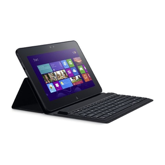
Overview Your Dell Latitude 10-ST2 tablet is built for business with easy management and security. It provides: • world class security • easy management • long term stability It is shipped with Windows 8 operating system to fully utilize the touch experience. -
Page 8: Using A Stylus In A Tablet
Using a Stylus in a Tablet The stylus allows you to actively navigate through the menus. You can use it as a mouse and also as a pen. Using the Stylus as a Mouse You can use the stylus the same way you use a mouse or touch pad with a notebook computer. Holding the stylus near the display makes a small cursor appear. -
Page 9: Entering Text
2. Go to Folder options. 3. Click View. 4. Under Advanced settings , select the Use check boxes to select items check box, and then click OK. Entering Text You can use handwriting recognition application or the touch keyboard to enter text. Table 2. -
Page 10: Pen And Touch Settings
Pen and Touch Settings Using the stylus, you can adjust how quickly you tap the screen when you double-tap the screen. It also allows you define the spatial tolerance. The Press and Hold settings allow you to define the speed and the duration for a right-click action. -
Page 11: Touch Usage
Touch Usage One of the key advantages of the Tablet PC is the ability to easily switch from pen input to touch input. When you use Touch Mode , a translucent image of a computer mouse, called the touch pointer, floats beneath your finger. -
Page 13: Removing And Installing Components
Removing and Installing Components This section provides detailed information on how to remove or install the components from your computer. Recommended Tools The procedures in this document may require the following tools: • Small flat-blade screwdriver • #0 Phillips screwdriver •... -
Page 14: Removing The Battery
Figure 2. Internal View 1. docking board 6. rear camera 2. coin-cell battery 7. SmartCard reader/WWAN card (WWAN card is located below the SmartCard reader 3. speaker 4. system board 5. front camera Removing the Battery Before Working Inside Your Computer . Follow the procedures in Slide the battery release latch to the unlock position. -
Page 15: Installing The Battery
Installing the Battery Slide the battery into its slot until it clicks into place. After Working Inside Your Computer. Follow the procedures in Removing the Base Cover Before Working Inside Your Computer . Follow the procedures in Remove the battery. Remove the screws that secure the base cover to the computer. - Page 16 Pry and release the tabs that secure the base cover by following the arrow sequence in the diagram. Pry and lift the tabs that secure the base cover in the battery bay area in an upward direction. Pry and flip the base cover.
-
Page 17: Installing The Base Cover
Lift the retention clasp in an upward direction and release the fingerprint reader cable outward to remove it from the system board. Lift the base cover away from the computer. Installing the Base Cover Attach the fingerprint reader flex cable from the base cover to the system board. Attach the base cover to the computer. -
Page 18: Installing The Front Camera
Installing the Front Camera Place the camera module in its slot on the computer. Tighten the screw to secure the camera module to the computer. Connect the camera cable to the connector. Install the: a) base cover b) battery Follow the procedures in After Working Inside Your Computer . - Page 19 Un-route the speaker cables on the right-hand side of the computer and lift up to release the right speaker from the computer. Un-route the speaker cables on the left-hand side of the computer and lift up to release the left speaker from the computer.
-
Page 20: Installing The Speakers
Installing the Speakers Place the right and the left speakers in their slot. Route the speaker cables on the chassis. Tighten the screws to secure the speakers to the chassis. Place the coin-cell battery in its slot and route the cables. Connect the speaker connector cable to its port on the system board. -
Page 21: Installing The Smartcard Reader
Installing the SmartCard Reader Place the SmartCard reader into its slot. Tighten the screws to secure the SmartCard reader to the system board. Install the : a) base cover b) battery Follow the procedures in After Working Inside Your Computer. Removing the Wireless Wide Area Network (WWAN) Card NOTE: The WWAN Card is an optional component. -
Page 22: Installing The Wireless Wide Area Network (Wwan) Card
Disconnect the screws that secure the WWAN card to the system board and lift it up to remove it from the computer. Installing the Wireless Wide Area Network (WWAN) Card Slide the WWAN card into the slot. Tighten the screws to secure the WWAN card to the computer. Connect the system board side data cable to the WWAN card. -
Page 23: Installing The Docking Board
Remove the docking board from the computer and disconnect the home-button board cable. Installing the Docking Board Connect the home-button board cable to the docking board and place the docking board in its slot in the computer. Tighten the screws to secure the docking board to the computer. Connect the docking board power flex cable to the connector. -
Page 24: Installing The System Board
f) front camera g) docking board Disconnect the LVDS and docking board flex cables. Remove the screws that secure the system board to the computer. Lift up the system board at a 45° angle and pull it away from the computer. Installing the System Board Place the system board in its compartment on the computer. -
Page 25: Removing The Rear Camera
e) SmartCard reader f) base cover g) battery After Working Inside Your Computer . Follow the procedures in Removing the Rear Camera Before Working Inside Your Computer . Follow the procedures in Remove the: a) battery b) base cover c) SmartCard reader d) WWAN Card e) speaker f) front camera... -
Page 26: Removing The Coin-Cell Battery
After Working Inside Your Computer . Follow the procedures in Removing the Coin-Cell Battery Follow the procedures in Before Working Inside Your Computer . Remove the: a) battery b) base cover c) SmartCard reader d) WWAN Card e) speaker f) front camera g) system board Disconnect the coin-cell battery cable and remove it from the system board. - Page 27 After Working Inside Your Computer. Follow the procedures in...
-
Page 29: System Setup
Turn on (or restart) your computer. When the blue DELL logo is displayed, you must watch for the F2 prompt to appear. Once the F2 prompt appears, press <F2> immediately. -
Page 30: Boot Menu
Boot Menu Press <F12> when the Dell logo appears to initiate a one-time boot menu with a list of the valid boot devices for the system. Hard Drive Network Diagnostics and Enter Setup options are included in this menu. The devices listed on the boot menu depend on the bootable devices in the system. - Page 31 Table 5. Boot Sequence Option Function File Browser Add Boot Option Displays the order that the BIOS searches devices when trying to find an operating system to boot. A new device can be added here. File Browser Del Boot Option A displayed boot device can be removed from the boot order.
- Page 32 Option Description Click OK after entering the password details. System Password Allows you to set, change, or delete the computer password (previously called the primary password). The drive does not have a password set by default. To add a new password: •...
- Page 33 Option Description Admin Setup Lockout Allows you to enable or disable the option to enter setup when an admin password is set. • Enable Admin Setup Lockout (Default) Table 10. Secure Boot Option Function Secure Boot Enables or Disables the secure boot feature. Default : Disabled Expert Key Management Allows you to manage all secure boot keys.
- Page 34 Option Description • Disabled - Does not allow the system to power on by special LAN signals when it receives a wake-up signal from the LAN or wireless LAN. (Default ) • LAN Only - Allows the system to be powered on by special LAN signals. Table 13.
-
Page 35: Troubleshooting Your Computer
Troubleshooting Your Computer You can troubleshoot your computer using indicators like Diagnostic Lights, Beep Codes, and Error Messages during the operation of the computer. Enhanced Pre-boot System Assessment (ePSA) The ePSA is a diagnostic utility available on your computer. This utility includes a series of tests for a computer's hardware. -
Page 36: Beep Codes
During the testing process, you will be prompted to answer a YES or NO question. To respond, press Volume Up = YES or Volume Down = NO. Press the Security Button (<Ctrl> + <Alt> + <Del>) to click OK once the tests are completed. The volume up and down buttons can also be used as the <Tab>... -
Page 37: Led Error Codes
Code Cause and Troubleshooting Steps BIOS ROM checksum in progress or failure System board failure, covers BIOS corruption or ROM error No RAM detected No memory detected Chipset Error (North and South Bridge Chipset, DMA/IMR/ Timer Error) , Time-Of-Day Clock test failure , Gate A20 failure , Super I/O chip failure , Keyboard controller test failure System board failure RAM Read/Write failure... -
Page 38: Troubleshooting The Wacom Digitizer
Code Cause and Troubleshooting Steps CMOS battery failure Video BIOS test failure Video card failure CPU - cache test failure Processor failure Display Display failure Troubleshooting the Wacom Digitizer The Wacom Tablet Settings applet is used to adjust several settings for the digitizer. Once the Wacom drivers are loaded, an icon appears in the system tray. -
Page 39: Specifications
Specifications NOTE: Offerings may vary by region. The following specifications are only those required by law to ship with your computer. For more information regarding the configuration of your computer, click Start → Help and Support and select the option to view information about your computer. System Information Chipset Intel Atom Z2760... - Page 40 Communications Network adapter USB 2.0 based Gigabit LAN via dock Wireless mobile broadband card (optional) Ports and Connectors Audio one microphone-in and stereo headphones/speakers combo connector Video one mini HDMI connector one USB 2.0 connector Memory card reader one 3-in-1 memory card reader Display Type HD IPS LED...
- Page 41 Battery Temperature range Operating 0 °C to 50 °C (32° F to 158 °F) 0 °C to 50 °C (32 °F to 158 °F) Non-Operating -20 °C to 65 °C ( –4 °F to 149 °F) -20 °C to 65 °C ( –4 °F to 149 °F) Coin-cell battery 3 V CR2025 lithium ion AC Adapter...
-
Page 43: Contacting Dell
Dell product catalog. Dell provides several online and telephone-based support and service options. Availability varies by country and product, and some services may not be available in your area. To contact Dell for sales, technical support, or customer service issues: Visit dell.com/support...