Table of Contents

Related Manuals for Dell PowerConnect W-Series FIPS


Summary of Contents for Dell PowerConnect W-Series FIPS
- Page 1 FIPS 140-2 Non-Proprietary Security Policy for Aruba AP-92, AP-93, AP-105, AP-175 Dell W- AP92, W-AP93, W-AP105 and W-AP175 Wireless Access Points Version 1.2 Feb. 2012 Aruba Networks™ 1322 Crossman Ave. Sunnyvale, CA 94089-1113...
-
Page 3: Table Of Contents
INTRODUCTION ..........................5 ......................5 RUBA ELATIONSHIP ..................... 5 CRONYMS AND BBREVIATIONS PRODUCT OVERVIEW ........................7 AP-92 ..............................7 2.1.1 Physical Description ........................7 2.1.1.1 Dimensions/Weight ......................8 2.1.1.2 Interfaces ..........................8 2.1.1.3 Indicator LEDs ........................8 AP-93 ..............................9 2.2.1 Physical Description ........................ - Page 4 3.2.5 AP-175 TEL Placement ......................23 3.2.5.1 To detect access to restricted ports: ...................23 3.2.5.2 To detect opening of the chassis cover: ................23 3.2.6 Inspection/Testing of Physical Security Mechanisms ...............25 ........................26 ODES OF PERATION 3.3.1 Configuring Remote AP FIPS Mode ..................26 3.3.2 Configuring Control Plane Security (CPSec) protected AP FIPS mode ........27 3.3.3...
-
Page 5: Introduction
This document can be freely distributed. 1.1 Aruba Dell Relationship Aruba Networks is the OEM for the Dell PowerConnect W line of products. Dell products are identical to the Aruba products other than branding and Dell software is identical to Aruba software other than branding. - Page 6 Gigabit Ethernet Gigahertz HMAC Hashed Message Authentication Code Hertz Internet Key Exchange IPSec Internet Protocol security Known Answer Test Key Encryption Key L2TP Layer-2 Tunneling Protocol Local Area Network Light Emitting Diode Secure Hash Algorithm SNMP Simple Network Management Protocol SPOE Serial &...
-
Page 7: Product Overview
The plastic case physically encloses the complete set of hardware and software components and represents the cryptographic boundary of the module. The Access Point configuration tested during the cryptographic module testing included: Aruba Part Number Dell Corresponding Part Number AP-92-F1 W-AP92-F1... -
Page 8: Dimensions/Weight
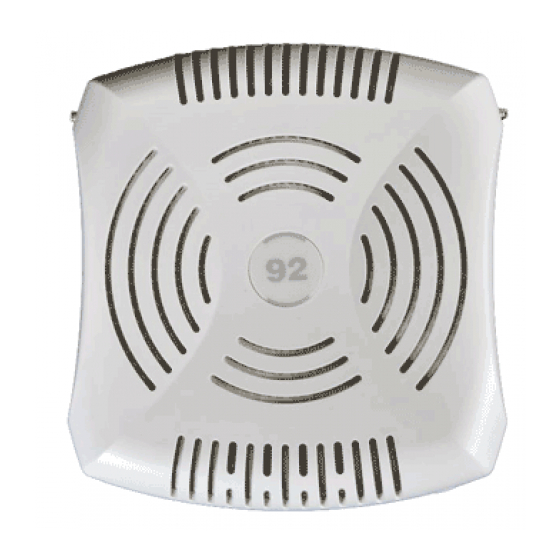
The exact firmware versions tested were: ArubaOS_6xx_6.1.2.3-FIPS Dell_PCW_6xx_6.1.2.3-FIPS 2.1.1.1 Dimensions/Weight The AP has the following physical dimensions: 120 mm x 130 mm x 35 mm (4.7" x 5.1" x 1.4") 255 g (9 oz) 2.1.1.2 Interfaces The module provides the following network interfaces: ... -
Page 9: Physical Description
Label Function Action Status On – Green 2.4GHz radio enabled in 802.11n mode Flashing - Green 2.4GHz Air monitor or RF protect sensor 11a/n 5GHz Radio Status 5GHz radio disabled On - Amber 5GHz radio enabled in WLAN mode On – Green 5GHz radio enabled in 802.11n mode Flashing - Green... -
Page 10: Dimensions/Weight
The plastic case physically encloses the complete set of hardware and software components and represents the cryptographic boundary of the module. The Access Point configuration tested during the cryptographic module testing included: Aruba Part Number Dell Corresponding Part Number AP-93-F1 W-AP93-F1 The exact firmware versions tested were: ... -
Page 11: Ap-105 Series
Label Function Action Status Flashing Ethernet link activity 11b/g/n 2.4GHz Radio Status 2.4GHz radio disabled On – Amber 2.4GHz radio enabled in WLAN mode On – Green 2.4GHz radio enabled in 802.11n mode Flashing - Green 2.4GHz Air monitor or RF protect sensor 11a/n 5GHz Radio Status... -
Page 12: Physical Description
The plastic case physically encloses the complete set of hardware and software components and represents the cryptographic boundary of the module. The Access Point configuration tested during the cryptographic module testing included: Aruba Part Number Dell Corresponding Part Number AP-105-F1 W-AP105-F1 The exact firmware versions tested were: ... -
Page 13: Ap-175 Series
ENET Ethernet Network Link Ethernet link unavailable Status / Activity On – Amber 10/100Mbs Ethernet link negotiated On – Green 1000Mbs Ethernet link negotiated Flashing Ethernet link activity 11b/g/n 2.4GHz Radio Status 2.4GHz radio disabled On – Amber 2.4GHz radio enabled in WLAN mode On –... -
Page 14: Physical Description
The hard case physically encloses the complete set of hardware and software components and represents the cryptographic boundary of the module. The Access Point configuration tested during the cryptographic module testing included: Aruba Part Number Dell Corresponding Part Number AP-175P-F1 W-AP175P-F1 AP-175AC-F1... -
Page 15: Indicator Leds
2.4.1.3 Indicator LEDs There is an array of LEDs which operate as follows: Table 5- AP-175 Indicator LEDs Label Function Action Status Position AP power / system status No power to AP System Alarm Flashing - Green Power did not connect well or equipment failure On - Green Device ready... -
Page 16: Module Objectives
3 Module Objectives This section describes the assurance levels for each of the areas described in the FIPS 140-2 Standard. In addition, it provides information on placing the module in a FIPS 140-2 approved configuration. 3.1 Security Levels Section Section Title Level Cryptographic Module Specification Cryptographic Module Ports and Interfaces... -
Page 17: Tel Placement
3.2.2 AP-92 TEL Placement This section displays all the TEL locations of the Aruba AP-92. The AP-92 requires a minimum of 3 TELs to be applied as follows: 3.2.2.1 To detect access to restricted ports: Spanning the serial port 3.2.2.2 To detect opening of the chassis cover: Spanning the bottom and top chassis covers on the right side Spanning the bottom and top chassis covers on the left side... - Page 18 Figure7 - Aruba AP-92 Tel placement right view Figure 8 - Aruba AP-92 Tel placement top view...
-
Page 19: Tel Placement
Figure 9 - Aruba AP-92 Tel placement bottom view 3.2.3 AP-93 TEL Placement This section displays all the TEL locations of the Aruba AP-93. The AP-93 requires a minimum of 3 TELs to be applied as follows: 3.2.3.1 To detect access to restricted ports: Spanning the serial port 3.2.3.2 To detect opening of the chassis cover:... - Page 20 Figure 11 - Aruba AP-93 Tel placement left view Figure 12 - Aruba AP-93 Tel placement right view Figure 13 - Aruba AP-93 Tel placement bottom view...
-
Page 21: Ap-105 Tel Placement
Figure 14 - Aruba AP-93 Tel placement top view 3.2.4 AP-105 TEL Placement This section displays all the TEL locations of the Aruba AP-105. The AP-105 requires a minimum of 3 TELs to be applied as follows: 3.2.4.1 To detect opening of the chassis cover: Spanning the bottom and top chassis covers on the left side Spanning the bottom and top chassis covers on the right side 3.2.4.2... - Page 22 Figure 16 - Aruba AP-105 Tel placement left view Figure 17 - Aruba AP-105 Tel placement right view Power Input Inlet Figure 18 - Aruba AP-105 Tel placement top view...
-
Page 23: Ap-175 Tel Placement
Figure 19 - Aruba AP-105 Tel placement bottom view 3.2.5 AP-175 TEL Placement This section displays all the TEL locations of the Aruba AP-175. The AP-175 requires a minimum of 6 TELs to be applied as follows: 3.2.5.1 To detect access to restricted ports: Spanning the USB console port Spanning the power connector plug (AP-175P only) Spanning the hex screw... - Page 24 Figure 20 - Aruba AP-175 Tel placement back view Figure 21 - Aruba AP-175 Tel placement left view Figure 22 - Aruba AP-175 Tel placement right view...
-
Page 25: Inspection/Testing Of Physical Security Mechanisms
Figure 23 - Aruba AP-175 Tel placement top view Figure 24 - Aruba AP-175 Tel placement bottom view 3.2.6 Inspection/Testing of Physical Security Mechanisms Physical Security Mechanism Recommended Test Frequency Guidance Tamper-evident labels (TELs) Once per month Examine for any sign of removal, replacement, tearing, etc. -
Page 26: Modes Of Operation
3.3 Modes of Operation The module has the following FIPS approved modes of operations: • Remote AP (RAP) FIPS mode – When the module is configured as a Remote AP, it is intended to be deployed in a remote location (relative to the Mobility Controller). The module provides cryptographic processing in the form of IPSec for all traffic to and from the Mobility Controller. -
Page 27: Configuring Control Plane Security (Cpsec) Protected Ap Fips Mode
If the staging controller does not provide PoE, either ensure the presence of a PoE injector for the LAN connection between the module and the controller, or ensure the presence of a DC power supply appropriate to the particular model of the module. Connect the module via an Ethernet cable to the staging controller;... -
Page 28: Configuring Remote Mesh Portal Fips Mode
Connect the module via an Ethernet cable to the staging controller; note that this should be a direct connection, with no intervening network or devices; if PoE is being supplied by an injector, this represents the only exception. That is, nothing other than a PoE injector should be present between the module and the staging controller. -
Page 29: Configuring Remote Mesh Point Fips Mode
the AP as Remote Mesh Portal by filling in the form appropriately. Detailed steps are listed in Section “Provisioning an Individual AP” of Chapter “The Basic User-Centric Networks” of the Aruba OS User Guide. Click “Apply and Reboot” to complete the provisioning process. During the provisioning process as Remote Mesh Portal, if Pre-shared key is selected to be the Remote IP Authentication Method, the IKE pre-shared key (which is at least 8 characters in length) is input to the module during provisioning. -
Page 30: Verify That The Module Is In Fips Mode
represents the only exception. That is, nothing other than a PoE injector should be present between the module and the staging controller. Once the module is connected to the controller by the Ethernet cable, navigate to the Configuration > Wireless > AP Installation page, where you should see an entry for the AP. -
Page 31: Logical Interfaces
3.5 Logical Interfaces The physical interfaces are divided into logical interfaces defined by FIPS 140-2 as described in the following table. Table 6 - FIPS 140-2 Logical Interfaces FIPS 140-2 Logical Interface Module Physical Interface Data Input Interface 10/100/1000 Ethernet Ports 802.11a/b/g/n Radio Transceiver Data Output Interface 10/100/1000 Ethernet Ports... -
Page 32: Roles, Authentication And Services
4 Roles, Authentication and Services 4.1 Roles The module supports the roles of Crypto Officer, User, and Wireless Client; no additional roles (e.g., Maintenance) are supported. Administrative operations carried out by the Aruba Mobility Controller map to the Crypto Officer role. The Crypto Officer has the ability to configure, manage, and monitor the module, including the configuration, loading, and zeroization of CSPs. -
Page 33: User Authentication
4.1.2 User Authentication Authentication for the User role depends on the module configuration. When the module is configured as a Remote Mesh Portal FIPS mode and Remote Mesh Point FIPS mode, the User role is authenticated via the WPA2 pre-shared key. When the module is configured as a Remote AP FIPS mode and CPSec protected AP FIPS mode, the User role is authenticated via the same IKEv1/IKEv2 pre-shared key/RSA certificate that is used by the Crypto Officer 4.1.3 Wireless Client Authentication... - Page 34 Authentication Mechanism Strength Mechanism Wireless Client For WPA2-PSK there are at least 95^16 (=4.4 x 10^31) possible WPA2-PSK combinations. In order to test a guessed key, the attacker must complete the (Wireless Client 4-way handshake with the AP. Prior to completing the 4-way handshake, the role) attacker must complete the 802.11 association process.
-
Page 35: Services
4.2 Services The module provides various services depending on role. These are described below. 4.2.1 Crypto Officer Services The CO role in each of FIPS modes defined in section 3.3 has the same services Service Description CSPs Accessed (see section 6 below for complete description of CSPs) FIPS mode enable/disable... -
Page 36: User Services
Service Description CSPs Accessed (see section 6 below for complete description of CSPs) Creation/use of secure The module supports use of IKEv1/IKEv2 Preshared management session between IPSec for securing the Secret module and CO management channel. DH Private Key ... -
Page 37: Wireless Client Services
Service Description CSPs Accessed (see section 6 below for complete description of CSPs) 802.11i AES-CCM key 802.11i GMK 802.11i GTK Use of WPA pre-shared key for When the module is in mesh establishment of IEEE 802.11i configuration, the inter-module ... - Page 38 System status – SYSLOG and module LEDs 802.11 a/b/g/n TFTP GRE tunneling of 802.11 wireless user frames (when acting as a “Local AP”) Reboot module by removing/replacing power Self-test and initialization at power-on...
-
Page 39: Cryptographic Algorithms
5 Cryptographic Algorithms FIPS-approved cryptographic algorithms have been implemented in hardware and firmware. The firmware supports the following cryptographic implementations. ArubaOS OpenSSL AP Module implements the following FIPS-approved algorithms: AES (Cert. #1851) HMAC (Cert. #1099) RNG (Cert. #970) RSA (Cert. #934) SHS (Cert. -
Page 40: Critical Security Parameters
Critical Security Parameters The following Critical Security Parameters (CSPs) are used by the module: STORAGE CSP TYPE GENERATION ZEROIZATI Encryption Triple-DES Hard-coded Stored in flash, Encrypts (KEK) 168-bits key zeroized by the IKEv1/IKEv2 ‘ap wipe out preshared keys flash’ command. configuration parameters IKEv1/IKEv2 Pre-shared... - Page 41 STORAGE CSP TYPE GENERATION ZEROIZATI IKEv1/IKEv2 Diffie- 1024-bit Generated internally Stored in Used in Hellman Private key Diffie- during IKEv1/IKEv2 plaintext in establishing Hellman negotiation volatile the session key private key memory; for IPSec zeroized when session is closed or system is powered off IKEv1/IKEv2 Diffie-...
- Page 42 STORAGE CSP TYPE GENERATION ZEROIZATI WPA2 PSK 16-64 CO configured Encrypted in Used to derive character flash using the the PMK for shared secret KEK; zeroized 802.11i mesh used to by updating connections authenticate through between APs mesh administrative and in connections interface, or by advanced...
- Page 43 STORAGE CSP TYPE GENERATION ZEROIZATI 802.11i Group Master Key 256-bit Generated from approved Stored in Used to derive (GMK) secret used plaintext in Group to derive volatile Transient Key memory; (GTK) zeroized on reboot 802.11i Group Transient 256-bit Internally derived by AP Stored in Used to derive Key (GTK)
-
Page 44: Self Tests
7 Self Tests The module performs the following Self Tests after being configured into either Remote AP mode or Remote Mesh Portal mode. The module performs both power-up and conditional self-tests. In the event any self-test fails, the module enters an error state, logs the error, and reboots automatically. The module performs the following power-up self-tests: ... - Page 45 Self-test results are written to the serial console. In the event of a KATs failure, the AP logs different messages, depending on the error. For an ArubaOS OpenSSL AP module and ArubaOS cryptographic module KAT failure: AP rebooted [DATE][TIME] : Restarting System, SW FIPS KAT failed For an AES Atheros hardware POST failure: Starting HW SHA1 KAT ...Completed HW SHA1 AT Starting HW HMAC-SHA1 KAT ...Completed HW HMAC-SHA1 KAT...