
Related Manuals for Draytek VigorTalk ATA-24


Summary of Contents for Draytek VigorTalk ATA-24
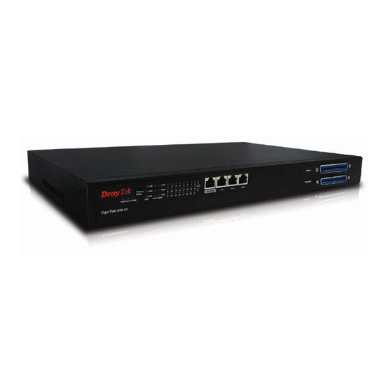
- Page 1 VigorTalk ATA-24 24-Port Analogue Terminal Adapter User’s Guide Version: 1.01 Date: 28/05/2009 VigorTalk ATA24 Series User’s Guide...
-
Page 2: Copyright Information
Copyright Information Copyright Copyright 2009 All rights reserved. This publication contains information that is Declarations protected by copyright. No part may be reproduced, transmitted, transcribed, stored in a retrieval system, or translated into any language without written permission from the copyright holders. -
Page 3: Table Of Contents
Preface .......................1 1.1 LED Indicators and Connection ....................2 1.2 Hardware Installation ......................4 1.2.1 Detailed Explanation for the Connector................5 Configuring Basic Settings ................7 2.1 Changing Password ........................ 7 2.2 Quick Setup..........................9 2.2.1 Adjusting WAN Connection Mode ..................9 2.2.2 Static Mode........................ - Page 4 3.5.6 Nat Traversal ........................57 3.5.7 Line Test ......................... 58 3.5.8 Miscellaneous ......................... 59 3.5.9 Incoming Call Barring ..................... 65 3.5.10 Statistics ........................67 3.5.11 Status..........................71 3.5.12 Call History ........................74 3.5.13 Configure Activate ......................75 Trouble Shooting .....................77 4.1 Checking If the Hardware Status Is OK or Not..............
- Page 5 A.6.6 Auto Logout Commands....................97 A.6.7 Config Commands......................97 A.6.8 Manage Port Commands ....................98 A.6.9 Reboot Commands ......................98 A.6.10 Show Status Command....................98 A.6.11 Syslogd Commands ..................... 99 A.6.13 Upgrade Commands ....................99 A.7 Voip Commands ......................... 100 A.7.1 General Commands .....................
-
Page 7: Preface
The VigorTalk ATA-24 series integrates a rich suite of functions. These products are very suitable for providing multi-integrated solutions to SME markets. An application scenario for the VigorTalk ATA-24 is depicted in Figure 1-1, which illustrates interconnections among branch offices through the Internet via the VigorTalk ATA-24 adapter. By combining with an existing PBX, an Internet phone from a remote branch can also access any extension number on a local PBX or a traditional phone via PSTN. -
Page 8: Led Indicators And Connection
The VigorTalk ATA-24 has 2 WAN interfaces. Each interface can be connected to an individual Internet Service Provider. The VigorTalk ATA-24 also supports a backup function for WAN interfaces – a user can select one WAN interface to be a backup interface. If the master interface fails, the backup interface will take the place of the master interface immediately. - Page 9 Status Explanation It means that a normal 1000 Mbps connection is 1000 through its corresponding port. It means that a normal 100 Mbps connection is through its corresponding port. It means a full duplex connection on corresponding port. It means a half duplex connection on corresponding port.
-
Page 10: Hardware Installation
Before starting to configure the adapter, you have to connect your devices correctly. Connect one end of an Ethernet cable (RJ-45) to the MGN ports of VigorTalk ATA-24. Connect the other end of the cable (RJ-45) to the Ethernet port on your computer. -
Page 11: Detailed Explanation For The Connector
RJ45 cables. These cables are used on WAN, LAN, and DMZ interfaces. The VigorTalk ATA-24 can be mounted on a rack by using standard brackets in a 19-inch rack or optional larger brackets on 23-inch rack (not included). The bracket for 19- and 23-inch racks are shown below. - Page 12 After the bracket installation, the VigorTalk ATA-24 chassis can be installed in a rack by using four screws for each side of the rack. Rubber pads are included with the VigorTalk ATA-24. These rubber pads improve the air circulation and decrease unnecessary rubbing on the desktop.
-
Page 13: Configuring Basic Settings
For use the adapter properly, it is necessary for you to change the password of web configuration for security and adjust primary basic settings. This chapter explains how to setup a password for an administrator and how to adjust basic settings for accessing Internet successfully. - Page 14 Now, the Main Screen will pop up. Go to System page and choose Change Password. The following screen will appear. Enter the login password (1234) on the field of Old Password. Type a new one in the field of New Password and retype it on the field of Confirm Password. Then click Apply to continue.
-
Page 15: Quick Setup
Quick Setup is designed for configuring your broadband adapter accessing Internet with simply steps. There are two phases of quick setup, one is WAN configuration and the other is LAN configuration. In the Quick Setup group, you can configure the adapter to access the Internet with different modes such as Static and DHCP modes. - Page 16 Assign the transmission rate for this WAN interface. The default value is 102400 kbps (100 Megabit). This setting is very important for VigorTalk ATA-24 outgoing buffer adjustment. If you use a DSL subscriber service with a 256Kbps downstream, please set the downstream rate setting with 256Kbps.
-
Page 17: Static Mode
You can manually assign a static IP address to the WAN interface and complete the configuration by applying the settings and rebooting your adapter. Choosing Static as the IP mode, you will see the following page: All the settings here are set by privately. Your ISP will not provide these settings. IP Address Assign a private IP address to the WAN interface. - Page 18 LAN – LAN IP/DHCP Page IP Address Assign an IP address for the LAN interface. Subnet Mask Assign the subnet mask for the LAN interface. Status Click Enable to use DHCP server; click Disable to close DHCP server. Start IP Assign the start IP address of the IP pool that DHCP server can use for clients in LAN.
-
Page 19: Dhcp Mode
If you choose DHCP mode, the DHCP server of your ISP will assign a dynamic IP address for VigorTalk ATA-24 automatically. It is not necessary for you to assign any setting. (Host Name and Domain Name are required for some ISPs). S imply click Next to setup LAN interface. - Page 20 Primary DNS Type the IP address for primary DNS. Secondary DNS Type the IP address for secondary DNS. Lease Time Type the number for lease time. The default setting is 1440. Gateway IP Type the IP address as DHCP client. When you finished the above required settings, please click Finish.
-
Page 21: Advanced Configuration
The online Status function provides some useful system information on the current status of the VigorTalk ATA-24. A user can observe the system status on this Web page and determine which setting needed to be changed in corresponding web pages. In the System group, click the Status option. - Page 22 High Available Status The High Available Status is shown when the function is enabled. When there are two VigorTalk ATA-24 devices in the same LAN, one can be set as Master device and the other can VigorTalk ATA24 Series User’s Guide...
- Page 23 Master - It means that VigorTalk ATA-24 plays the Master role in high availability feature. Slave - It means that VigorTalk ATA-24 plays the Slave role in high availability feature. If there is only one VigorTalk ATA-24 used in LAN, this line will be blank.
-
Page 24: Time
The VigorTalk ATA-24 supports synchronization with a specific NTP server or the remote PC host of the administrator. In the System group, click the Time option. The Time page is... -
Page 25: Syslog
The VigorTalk ATA-24 supports a Syslog function to keep a record of abnormal conditions. The adapter will send Syslog packets to a Syslog server on the remote site. The administrator can observe any abnormal events from VigorTalk ATA-24. In the System group, click the Syslog option. -
Page 26: Access Control
This page allows you to determine which services (HTTP/Telnet/SSH) is used for the user to access VigorTalk ATA-24. In addition, you can also limit some hosts to access VigorTalk ATA-24 with specified IP address. In the System group, click the Access Control option. You will get the following page:... -
Page 27: Configuration
Most of the settings can be saved locally as a configuration file, and can be applied to another adapter. The VigorTalk ATA-24 supports the restoring and uploading functions of the configuration files. In the System group, click the Configuration Setup option. And you can see the following page. -
Page 28: Firmware Upgrade
1. Download the newest firmware from the DrayTek Website (www.draytek.com.tw) or FTP site (ftp.draytek.com) on your computer first. 2. Connect the RJ45 connector of console cable to the console port on VigorTalk ATA-24 and the DB9 connector of the console cable to the RS232 port on the PC. - Page 29 The default setting of the console port is “baud rate 115200, no parity, and 8 bit with 1 stop bit.” 3. Power on VigorTalk ATA-24, then press ENTER before the system reboots completely. 4. Type LAN IP, TFTP Server IP, Image Name one by one, and press ENTER.
-
Page 30: Commit
Commit can save the current settings. Please click Apply to save the VigorTalk ATA-24 system settings. The VigorTalk ATA-24 system can be restarted from a Web browser. Reboot screen can appear after you finish the changing of WAN and LAN settings. You have to reboot the adapter to invoke the configured settings that you made before. - Page 31 In some cases, a user may need to know some information about the adapter, such as static or dynamic databases, or other routing information. The VigorTalk ATA-24 supports four functions, Routing Table, ARP Cache Table, and DHCP Assignment Table for the user to review such information.
- Page 32 Select View ARP Cache Table to get the following page: IP Address Displays the IP address for different ARP cache. MAC Address Displays the MAC address for different ARP cache. Interface Denoted by vlan4040 if it is a LAN interface. vlan4041 means it is a WAN1 interface;...
-
Page 33: Network Setup
For Internet access, it is necessary for you to set WAN and MGN interfaces for the adapter. The VigorTalk ATA-24 supports two WAN interfaces (with two IP Modes – Static or DHCP), which share the same setting page. In the Network group, please click the WAN option. The following page will be shown. - Page 34 Cable modem. In most cases, you will get a DSL or cable modem from the broadband access service provider. VigorTalk ATA-24 is connected behind the broadband device i.e. DSL/cable modem and works as a NAT or IP adapter for broadband connections.
- Page 35 IP Address Sets the private IP address of WAN interface. Subnet Mask Sets the subnet mask value of WAN interface. Default Gateway Sets the private IP address of gateway. Primary DNS Sets the private IP address of primary DNS. Secondary DNS Sets the private IP address of secondary DNS.
- Page 36 No-Reply Count Assign detecting times to ensure the connection of the WAN. After passing the times you set in this field and no reply received by the adapter, the connection of WAN interface will be regarded as breaking down. Detect Destination Host Assign an IP address or Domain name as a destination to be (IP or Domain Name) detected whether the host is active (sending reply to the...
- Page 37 If the WAN interface is set as a DHCP client, the VigorTalk ATA-24 will ask for IP network settings from the DHCP server or DSL modem automatically. It is not necessary for users to manually configure the adapter. It means the maximum transmission unit. Default value is 1500.
-
Page 38: Mgn
adapter) or not. If not, the connection of WAN interface will be regarded as breaking down. This function is available when Detect Type is set with Send PING or Send Http Request. Apply Click Apply to go back to the WAN Interface Configuration page. -
Page 39: High Availability
Secondary DNS Sets the private IP address of the secondary DNS. Lease Time (Min) Sets a lease time for the DHCP server. The time unit is minute. Gateway IP (Optional) Sets a gateway IP address for the DHCP server. Click Apply to reboot the system and apply the settings. The High Availability (HA) feature refers to the awareness of component failure and the availability of backup resources. -
Page 40: Advanced Setup
High Availability Disables or enables this function. When the master device fails down, the slave device will take its work over. Group Number Assign a group number. The range is from 1 to 255. PCs on the same group (in LAN) can support for each other. Role Select a role for this device as Master or Slave. - Page 41 Network Interface Displays the network interface (LAN, WAN1, 2, 3 or 4). Gateway IP Displays the gateway address of the static route. Destination IP Displays the destination IP of the static route. Mask Displays the subnet mask of this route. Edit Allows users to edit the selected static route settings.
-
Page 42: Port Block
(both TCP and UCP) of packets with these assigned port numbers are on WAN and LAN. The advantage of this feature is to filter some unnecessary packets or attacking packets on Internet environment or LAN network. VigorTalk ATA-24 supports ten port numbers to be blocked. -
Page 43: Ddns
Index The number of each entry. Status User can Disable or Enable the port block for the specified port. Port Number Assign a port number to be blocked in system. The default port setting is 135. Click Apply to finish this setting. The Dynamic DNS function allows the adapter to update its online WAN IP address, which assigned by ISP or other DHCP server to the specified Dynamic DNS server. - Page 44 Select a specific interface for registering on DDNS server. The Interface should be any WAN port on VigorTalk series. Server Provider Assign a provider name to support DDNS server. The VigorTalk ATA-24 supports 7 domain server providers as default. VigorTalk ATA24 Series User’s Guide...
-
Page 45: Port Mirroring
Server Type Select Static, Dynamic or Custom type for this entry of DDNS settings. Domain Name Assign a private domain name to be accessed. Login Name Assign a name to login into DDNS server. Login Password Assign a password to login into DDNS server. Wild Card If you want anything-here.yourhost.dyndns.org to work (EX. -
Page 46: Firewall Setup
After finishing the settings, please click Apply. The firewall controls the allowance and denial of packets through the adapter. Firewall Setup in the VigorTalk ATA-24 Series mainly consists of Denial of Service (DoS) only. The firewall filters help to protect your computer against attack from outsiders. - Page 47 DoS Defense Enables or disables the DoS Defense function. The default value is Disable. Enable SYN Flood Defense Activates the SYN flood defense function. If the amount of TCP SYN packets from the Internet exceeds the user-defined threshold value, the adapter will be forced to randomly discard the subsequent TCP SYN packets within the user-defined timeout period.
- Page 48 Enable Block IP Options Activates the Block IP options function. The adapter will ignore any IP packets with IP option field appearing in the datagram header. Enable Block Land Activates the Block Land function. A Land attack occurs when an attacker sends spoofed SYN packets with identical source address, destination addresses and port number as those of the victim.
-
Page 49: Voip Setup
Voice over Internet Protocol (VoIP) is a technology that allows you to make telephone calls using a broadband Internet connection instead of a regular (or analog) phone line. The VigorTalk ATA-24 series provides cost effective voice solution for SME customers which can be explained with the following diagram. -
Page 50: Protocol
There are three protocols can be used for VoIP phones – SIP, MGCP and H248. You should click either one of buttons to set corresponding settings for VoIP phones. Be aware that both sides (local end and remote end) should use same protocol for VoIP phones. For SIP Configuration SIP Local Port Type the port number for SIP protocol. - Page 51 000504030201/1@[1.1.1.1] aaln/#@mac_addr- ex: aaln/1@000504030201 aaln/#@ - ex: aaln/1@v3300.draytek.com Logic ID Starting Number The starting number for “#” used in EndPoint Name Style. The range for the number is from 1 to 24. That is, if you type 3 in...
- Page 52 Send only one wild RSIP – Only one RSIP message (e.g., aaln/*@[172.16.3.5]) will be sent to call agent to indicate all ports are initiated/restarted. Range Wildcard RSIP Click Enable to send out RSIP message (e.g., aaln/*@[172.16.3.5]). Click Disable to close such function. HearBeat Click Enable to check if MGCP server can work normally or not, otherwise click Disable.
- Page 53 You have to set up your own SIP settings. When you apply for an account, your SIP service provider will give you relational information for you to type in this page. User Name 1001 ~ 1032 are the default name specified by the system. Please click Edit to modify it if necessary.
- Page 54 Disable/Enable Click Disable to close this setting. Click Enable to activate this setting. Username Enter your account name of SIP Address, e.g. every text before Password The password provided to you when you registered with a SIP service. Display Name The caller-ID that you want to be displayed on your friend’s screen.
- Page 55 voice phone. Call Forwarding There are four options for you to choose. Disable- It is to close call forwarding function. Callforwarding busy- It means the incoming calls will be forwarded into SIP URL only when the local system is busy. Callforwarding no answer after- It means if the incoming calls do not receive any response, they will be forwarded to the SIP URL by the time out.
-
Page 56: Port Settings
Port Settings page allows users to set phone number and phone groups for different call receivers. Edit Click this button to access into the Edit page for each phone number. Active Displays the status (active or not) for the VoIP connection. When this connection is active, a ‘v”... - Page 57 Port 1 Click Enable to activate this port or Disable to close this port. Default SIP Accounts – Choose one of the SIP account as the default setting. VoIP IP Address - The interface is used to apply VoIP traffics. There are two options: WAN and LAN/VPN.
-
Page 58: Speed Dial
When you finish all the configurations, please click this button to activate them. This page allows you to set a simple way to dial a specific number. Up to 150 numbers can be stored in VigorTalk ATA-24 Series. VigorTalk ATA24 Series User’s Guide... -
Page 59: Dial Plan
Speed Dial Phone Number Type the phone number to be used as quick dial. Speed Dial Destination Type the destination address of the dial. Memo Type a description for the specified number. Apply Click this button to activate the page settings. Clear This Page Click this button to remove all the settings in this page. - Page 60 Edit Click this button to access into the editing page of the speed dial. Delete/Delete All Click this button to delete the selected setting or all settings. To configure one entry, please click Edit to open the following page. Match String Assign a match String for this entry.
-
Page 61: Tone Settings
It is provided for fitting the telecommunication custom for the local area of the adapter installed. Wrong tone settings might cause inconvenience for users. To set the sound pattern of the phone set, simply choose a proper region to let the system find out the preset tone settings and caller ID type automatically. - Page 62 Congestion tone A tone means the network is busy. Low Frequency (Hz) Type the low frequency number in Hertz. High Frequency (Hz) Type the high frequency number in Hertz. TOn1 (10msec) Type the duration of the first ring. TOff1 (10msec) Type the silence duration after the first ring.
-
Page 63: Nat Traversal
If the router you use connects to Internet by other device, you have to set this function. This page is used to enable the Nat Traversal function. User could use it to enable the VoIP service under the NAT environment. Disable The default setting is disable. -
Page 64: Line Test
This page is used to diagnose the connection status for device, port and subscriber line. Port Choose one of the VoIP port for executing line test. Line Test Function Choose one of the test functions for executing line test. There are three types provided here, loop, line card and user phone. -
Page 65: Miscellaneous
Many settings that cannot be classified under VoIP are placed in this page, such as ring cadence, voice band data, MGCP port lock, offhook detect, line impedance and line PCM codec. This page includes RTP and T.38 Starting Port, T.38 Redundancy Number, VoIP FailOver, etc. - Page 66 RTP Starting Port The starting port number for RTP protocol packet. The default setting is 13456. T38 Mode Click Enable to enable T.38 function. Click Disable to close this function. T.38 Starting Port The starting port number for T.38 protocol packet. The default setting is 49170.
- Page 67 reversal while the remote user hangs off the phone call. VoIP FailOver Use POTS System – When VoIP call is unavailable, the system will switch into PSTN phone automatically. Echo Cancellation Click Enable to cancel echo. Click Disable to invoke echo. Echo Cancellation Tail …...
- Page 68 Ton1 Type the duration of the first ring. Toff1 Type the silence duration after the first ring. Ton2/Ton3/Ton4 Type the duration of the next continuous ring. Toff2/Toff3/Toff4 Type the silence duration after the next continuous ring. VBD means Voice Band Data which can determine Modem or Fax or Auto mode for data transmission according to the answering tone.
- Page 69 One by One When you click such item, you have to specify which ring port will be applied with the configuration set here. If you choose multiple ring ports, they will apply the configuration one by one. Such device has the ability to detect error automatically. When something wrong happened, the system will lock all the MGCP ports.
- Page 70 All Port When you click this button and choose any number from the drop down list, all the configurations will be applied to all ring ports. 8/10/12 – When the phone line current reaches 8mA/10mA/12mA, the system will judge the phone is off-hook. One by One When you click such item, you have to specify which ring port will be applied with the configuration set here.
-
Page 71: Incoming Call Barring
There are two types, A-LAW and –μLAW provided for such setting. Choose the suitable one according to the codec system used by ISP in different area. It will be applied for transferring analog signal into digital signal or transferring digital signal into analog signal while doing PCM codec sampling. - Page 72 Type the range to be checked. The default value is from 1 to 150. The VigorTalk ATA-24 supports up to 30 entries in the Allow List table. When you choose Allow only calls from allow list as the Barring Class, only the people listed in this list can call this adapter.
-
Page 73: Statistics
Otherwise, use the static IP address or DDNS domain name. The VigorTalk ATA-24 supports up to 30 entries in the Deny List table. When you choose Deny only calls from deny list as the Barring Class, people listed in this list cannot call this adapter. - Page 74 This page displays statistics for all incoming/outgoing calls (successful and failed) through this adapter. You can click Refresh to get the latest status information for these VoIP phones. In addition, you can set the time interval of refreshing. Use the drop down list of Refresh Option to choose an automatic refreshing setting.
- Page 75 You can click Refresh to get the latest status information for these VoIP phones. In addition, you can set the time interval of refreshing. Use the drop down list of Refresh Option to choose an automatic refreshing setting. If you choose No Refresh, the system will not refresh this page until you click Refresh button.
- Page 76 Mode Click Enable to activate RTP Threshold mode. Round Trip Delay Low Set the lowest value (default setting is 80) as round trip delay Threshold low threshold. Round Trip Delay High Set the highest value (default setting is 150) as round trip Threshold delay high threshold.
-
Page 77: Status
You can click Refresh to get the latest status information for these VoIP phones. In addition, you can set the time interval of refreshing. Use the drop down list of Refresh Option to choose an automatic refreshing setting. If you choose No Refresh, the system will not refresh this page until you click Refresh button. - Page 78 Call Status Display the calling status, idle, far-end alerting, alerting, busy, dialing and connected. RTP Statistics The statistics for RTP. PS means packets sent; OS means octets sent; PR means packet received; OR means octets received; PL means packets lost, LA means average TX delay (unit is ms) and JI means inter arrival jitter estimates (unit is ms).
- Page 79 Register Status The status (OK or Failed) of registering in proxy server. You can click Refresh to get the latest status information for these VoIP phones. In addition, you can set the time interval of refreshing. Use the drop down list of Refresh Option to choose an automatic refreshing setting.
-
Page 80: Call History
If you choose No Refresh, the system will not refresh this page until you click Refresh button. This page lists the call history through VigorTalk ATA-24. You can click Refresh to get the latest history information for these VoIP phones. Besides, this page refreshes automatically every 10 seconds. -
Page 81: Configure Activate
Release Reason The reason for the call termination. Remote RTP Address The IP address of remote voice site. Remote RTP Port The used port number of remote voice site. RTP Statistic The statistic of RTP with abbreviation will be shown in this field (e.g., PS: Packets Sent;... - Page 82 This page is left blank. VigorTalk ATA24 Series User’s Guide...
-
Page 83: Trouble Shooting
This section will guide you to solve abnormal situations if you cannot access into the Internet after installing the adapter and finishing the web configuration. Please follow below sections to check your basic installation stage by stage. Checking if the hardware status is OK or not. Checking if the Network Connection Settings on your computer is OK or not. - Page 84 The example is based on Windows XP. As to the examples for other operation systems, please refer to the similar steps or find support notes in www.draytek.com. Go to Control Panel and then double-click on Network Connections. Right-click on Local Area Connection and click on Properties.
- Page 85 Select Internet Protocol (TCP/IP) and then click Properties. Select Obtain an IP address automatically and Obtain DNS server address automatically. VigorTalk ATA24 Series User’s Guide...
- Page 86 1. Double click on the current used MacOs on the desktop. 2. Open the Application folder and get into Network. 3. On the Network screen, select Using DHCP from the drop down list of Configure IPv4. VigorTalk ATA24 Series User’s Guide...
-
Page 87: Pinging The Adapter From Your Computer
The default gateway IP address of the adapter is 192.168.1.1. For some reason, you might need to use “ping” command to check the link status of the adapter. The most important thing for this command is that the computer will receive a reply from 192.168.1.1 for correct link. - Page 88 Go to the web configuration GUI (http://192.168.1.1), click Network >> WAN to check your ISP settings for IP modes. Make sure the Active check box has been selected. Check if the values of IP Address, Subnet Mask, Gateway IP Address and Primary DNS that you got from ISP are set properly or not.
- Page 89 Check if Host Name (optional) and Domain Name (optional) are correct or not. Both them are required for some ISPs. If anything wrong, please check and retype correct values. Then try the network connection again. After finishing the settings, go to System - Status page and click WAN Status. You will get a correct web page of WAN settings.
-
Page 90: Backing To Factory Default Setting If Necessary
Sometimes, a wrong connection can be improved by returning to the default settings. Try to reset the adapter by software or hardware. Warning: After pressing factory default setting, you will lose all settings you did before. Make sure you have recorded all useful settings before you pressing. -
Page 91: Contacting Your Dealer
If the adapter settings are correct at all, and the adapter still does not connect to internet, please contact your ISP technical support representative to help you for configuration. Also, if the adapter still cannot work correctly, please contact your dealer for help. For any further questions, please send e-mail to support@draytek.com. VigorTalk ATA24 Series User’s Guide... -
Page 92: Appendix A: Telnet Commands
In addition to the SNMP management, users can use commands to configure the ATA-24 VoIP Board. Users can do telnet on the ATA-24 VoIP Board and use the following two ways. One is console interface; another is telnet by management port. The ATA-24 console interface will connect to PC console port. -
Page 93: Other Commands
- Enter network configuration function ATA24> network - Enter system configuration function ATA24> system - Enter voip configuration function ATA24> voip - Help ATA24> ? - Logout the CLI or the Telnet connection ATA24> exit ATA24> logout ATA24> quit - Enter advance configuration function ATA24>... -
Page 94: Staticroute Commands
<Enable> 0: Disable 1: Enable <Moirroring> Moirroring Port 1: WAN1 2: WAN2 <Mirror CPU> 0: Do not mirror, <Mirror LAN> 1: Mirror <Mirror WAN1> <Mirror WAN2> <Mirror WAN3> - Help ATA24/advance> staticroute ? - Display static route settings ATA24/advance> staticroute –s <Index> - Edit static route settings ATA24/advance>... -
Page 95: Netstat Commands
ATA24/diag> Learning_table - Help ATA24/diag> netstat ? - Netstat commands usage ATA24/diag> netstat -h - Netstat diagnostics utility ATA24/diag> netstat <cmd> - Help ATA24/diag> nslookup ? -Nslookup diagnostics utility ATA24/diag> nslookup <IPorDomainName> - Help ATA24/diag> ping ? - Ping commands usage ATA24/diag>... -
Page 96: Dos Commands
- Back to the root commands ATA24/ firewall > .. - Help ATA24/ firewall >dos ? - Set the icmpflood detection function ATA24/ firewall >dos /icmpflood - Set the packet block detection function ATA24/ firewall >dos/packetblock - Set the port scan detection function ATA24/ firewall >dos/ portscan - Set the synflood detection function ATA24/ firewall >dos/ synflood... -
Page 97: Network Commands
- Help ATA24/network>dos >portscan ? - Portscan commands usage ATA24/firewall/dos/portscan > enable <Option> ATA24/firewall/dos/portscan > threshold <Value> <Option> 0: disable port scan detection function 1: enable port scan detection function <Value> 0-65535, default=300 packets/sec - Help ATA24/network>dos >synflood ? - Portscan commands usage ATA24/firewall/dos/synflood >enable <Option>... -
Page 98: General Commands
- Enter network configuration function ATA24> network - Help in the network diagnostics function ATA24/network> ? - Back to the root commands ATA24/network> .. - Help ATA24/network>mgn ? - Set the dhcp mode ATA24/network/ mgn > dhcp - Set the IP address ATA24/network/ mgn >... -
Page 99: Wan Commands
- Help ATA24/network/ mgn >ip ? - Display nat setting ATA24/network/ mgn >ip –s - Edit IP_NAT setting ATA24/network/ mgn >ip –w <IP> <Netmask> <IP> IP address. <Netmask> Subnet mask for NAT. - Help ATA24/network/mgn>mac ? - Display IP route setting ATA24/network/mgn>mac 1 <Mac Address>... - Page 100 <loadbalance> 0: not join loadbalance 1: join loadbalance <backupmaster> 0: not backupmaster 1: backupmaster 0: not backupslave <backupslave> 1: backupslave - Help ATA24/network/wan>dhcp ? - Display current setting ATA24/network/wan>dhcp -s <index> - Edit WAN setting ATA24/network/wan>dhcp <index> ATA24/network/wan>dhcp <index> <hostname> <domainname> <index>...
- Page 101 <Downstream> 0: using default setting (102400) Type any number to set downstream rate. <Upstream> 0: using default setting(102400) Type any number to set upstream rate. - Help ATA24/network/wan>show ? - Display all WAN interfaces settings ATA24/network/wan> show - Display specified WAN interface settings ATA24/network/wan>show <index>...
-
Page 102: System Commands
<Secondary DNS> Private IP address as secondary DNS. - Help ATA24/network/wan>static_detect ? - Display current setting ATA24/network/wan> static_detect -s <index> - Set condition for detection, sending ARP to Gateway ATA24/network/wan> static_detect <index> 0 <detect interval> <No-Reply Count> - Set condition for detection, sending PING ATA24/network/wan>... -
Page 103: View Routing Table Command
ATA24/system/DiagnosticTools> dhcp assignment table - Help ATA24/system/DiagnosticTools> routingtable ? - Display the setting ATA24/system/DiagnosticTools> routing table - Help ATA24/system> administrator ? - Edit password for administrator ATA24/system>administrator<old password> <new password> <verify password> <old password> Type old password. <new password> Type new password. <verify password>... -
Page 104: Manage Port Commands
ATA24/system> config restore <fname> <servIP> <fname> Octets string maximum length is 64. <servIP> IP address for the IVD - Help ATA24/system> manage_port ? - Display the setting ATA24/system> manage_port -s - Manage port from WAN interface ATA24/system> manage_port -m <Use Default Port or Not><Manage from WAN>... -
Page 105: Syslogd Commands
ATA24/system> status ? - Display the system status ATA24/system> status - Help ATA24/system> syslogd ? - Display the syslog setting ATA24/system> syslogd -s - Set IP address and port number for Syslog server ATA24/system>syslogd <Active> <RIP> <RPort> <Facility> <Severity> <Active> 0: Disable 1: Enable <RIP>... -
Page 106: Voip Commands
- Enter voip configuration function ATA24> voip - Help in the voip diagnostics function ATA24/voip> ? - Back to the root commands ATA24/voip> .. - Help ATA24/voip>h248 ? - Display H248 call agent setting ATA24/voip/h248 > callagent -s - Edit the H248 call agent setting ATA24/voip/h248>callagent <IPAddress>... -
Page 107: Linetest Commands
<IP Mode> 0: WAN IPAddress 1: Manual IPAddress <Prefix> ID Name prefix <StartNum> Beginning of ID Name Number <Termination> 1 to 24 <ID> Identification name - Help ATA24/voip>linetest ? - Execute voip line card test ATA24/voip/linetest > line_card_test <Line> <TestItem> - Execute voip metallic loop test ATA24/voip/linetest >... - Page 108 - Display the MGCP heartbeat setting ATA24/voip/mgcp> heartbeat -s - Edit the dual_homing action ATA24/voip/mgcp> heartbeat <Active> - Edit the period of heartbeat for dual_homing ATA24/voip/mgcp> heartbeat –t <Sec> - Edit the retry times of dual_homing ATA24/voip/mgcp> heartbeat –r <Times> - Display local port setting ATA24/voip/mgcp>...
-
Page 109: Miscellaneous Commands
Disable) <Sec> Integer(1 to 65535 default=60) <Times> Integer(1 to 300 default=1) <Port> 1 to 24 (for port lock/unlock) <lock> 0: unlocked (default) 1: locked <wildcard> 1: Enable wildcard(*) RSIP(Default) 0: Disable wildcard(*) RSIP <range> 1: Enable range([1-24]) wildcards(Default) 0: Disable range([1-24]) wildcards - Help in the misc diagnostics function ATA24/voip>misc ? - Display the dialing completion timeout... - Page 110 ATA24/voip/misc> linepcmcodec <line> c - Display metering parameter ATA24/voip/misc> metering –s - Set metering parameter ATA24/voip/misc> metering ATA24/voip/misc> metering -r <Reversal as Callee off-hook> <Reversal as Callee on-hook> - Display NAT traversal setting ATA24/voip/misc> nat –s - Set NAT traversal setting ATA24/voip/misc>nat <Disable Mode>...
- Page 111 - Display Voice Band Data (VBD) Configuration ATA24/voip/misc> vbd -s - Set Voice Band Data (VBD) (same value for each line) ATA24/voip/misc> vbd <VBD> - Set Voice Band Data (VBD) ATA24/voip/misc> vbd <port><VBD> <value> Range: 1~60 (second) <enable> 0: disable 1: enable <tailLength>...
-
Page 112: Sip Commands
<interDigitMin> Minimum pulse inter digit time (ms) <Freqnency> Ring frequency 20: 20 HZ (default) 25: 25 HZ Pattern Index, Index Value: 1-8 <Index> <Ton1> Ton1 of cadence, unit: (ms) <Toff1> Toff1 of cadence, unit: (ms) <Ton2> Ton2 of cadence, unit: (ms) <Toff2>... - Page 113 ATA24/voip/misc> deny –s ATA24/voip/misc> deny -s <Index> - Edit deny list of incoming calls (for SIP) ATA24/voip/sip> deny -e <Index> <Name> <IP/Domain> - Delete deny list of incoming calls (for SIP) ATA24/voip/sip> deny -d <Index> ATA24/voip/sip> deny –d - Display current settings for incoming call barring (for SIP) ATA24/voip/misc>...
- Page 114 - Edit DTMF relay mode and SIP INFO mode for the port# ATA24/voip/sip>dtmf_relay <Port> <Mode> <SipInfoMode> ATA24/voip/sip>dtmf_relay -gain <port> <Gain Value> - Display fax transporting setting ATA24/voip/sip> fax -s - Edit fax mode for the port# ATA24/voip/sip> fax <Port> <Mode> - Display hotline setting ATA24/voip/sip>...
- Page 115 ATA24/voip/sip> sipua -e ATA24/voip/sip>dialplan -D - Display speed dial setting ATA24/voip/sip> speeddial –s ATA24/voip/sip> speeddial -s <start> <end> - Add speed dial number and destination for the entry ATA24/voip/sip> speeddial –a <Number> <Destination> <Memo> - Edit speed dial number, destination and memo for the entry ATA24/voip/sip>...
- Page 116 Detection, also known as Silence Suppression) function. “Disable” to stop using VAD. (Default is Disable) <Active> “Enable” to activate this port. “Disable” to close this port. (Default is Disable) 1 to 32 <SIP Account> <EntryIdx> 1 to 60 <MatchString> Matched string, ex: 9011x.T, maximum 63 characters.
- Page 117 1: Enable (It means that each SIP protocol packet will be sent to SIP proxy server always.) < ProxyName > Assign a name of SIP proxy server. (Default is none) < ProxyIP > Assign an IP address of SIP proxy server. (Default is 0) <...
-
Page 118: Statistics Commands
- Help in the Statistics function ATA24/voip/Statistics > ? - Display call statistics setting ATA24/voip/statistics> callstat - Display the setting by port ATA24/voip/statistics> callstat <Port> - Edit the range for callstat port <Range> ATA24/voip/statistics> callstat <Port> - Display RTP statistics setting ATA24/voip/statistics>... -
Page 119: Voip Status Commands
(10msec per unit) (Default is 0) <Type> 0: North America for call ID setting 1: JAPAN 2: ETSI (Default is 2) 3: DTMF - Help in the Statistics function ATA24/voip/status> ? - Display VoIP faults ATA24/voip/status>faultstatus - Display VoIP FXS port hook state (onhook or offhook) ATA24/voip/status>hookstate ATA24/voip/status>hookstate<Port>... - Page 120 ATA24/voip/tone/user_defined> dial -s - Edit frequency and cadence for dial tone ATA24/voip/tone/user_defined> dial <Lowfreq> <Highfreq> <Ton1> <Toff1> <Ton2> <Toff2> - Display user defined ringing tone setting ATA24/voip/tone/user_defined> ringing -s - Edit frequency and cadence for ringing tone ATA24/voip/tone/user_defined> ringing <Lowfreq> <Highfreq> <Ton1> <Toff1>...
-
Page 121: Config Commands
5: Special Dial Tone 6: Call waiting Tone 7: Congestion Tone 8: Reorder Tone <Timer> Range: 0~300 <sec> - Help ATA24/voip>protocol ? - Execute/activate VoIP setting ATA24/voip>config - Help ATA24/voip>listcmds ? - Display all VoIP CLI commands ATA24/voip>listcmds - Help ATA24/voip>protocol ? - Display the setting ATA24/voip>protocol -s...