Grizzly G0490 Owner's Manual
8" x 76" jointer w/ parallelogram beds
Hide thumbs
Also See for G0490:
- Owner's manual (60 pages) ,
- Parts breakdown (6 pages) ,
- Owner's manual (68 pages)
Table of Contents
Advertisement
MODEL G0490/G0490X
8" X 76" JOINTER
w/PARALLELOGRAM BEDS
OWNER'S MANuAL
Copyright © DECEMBEr, 2005 By grizzly inDustrial, inC., rEVisED oCtoBEr, 2012 (ts)
WARNING: NO PORTION Of ThIS MANuAL MAy BE REPRODucED IN ANy ShAPE
OR fORM WIThOuT ThE WRITTEN APPROvAL Of GRIzzLy INDuSTRIAL, INc.
(For MoDEls ManuFaCturED sinCE 3/09) #tr7845 printED in China
Advertisement
Table of Contents

Related Manuals for Grizzly G0490


Summary of Contents for Grizzly G0490
- Page 1 8" X 76" JOINTER w/PARALLELOGRAM BEDS OWNER'S MANuAL Copyright © DECEMBEr, 2005 By grizzly inDustrial, inC., rEVisED oCtoBEr, 2012 (ts) WARNING: NO PORTION Of ThIS MANuAL MAy BE REPRODucED IN ANy ShAPE OR fORM WIThOuT ThE WRITTEN APPROvAL Of GRIzzLy INDuSTRIAL, INc.
- Page 2 This manual provides critical safety instructions on the proper setup, operation, maintenance, and service of this machine/tool. Save this document, refer to it often, and use it to instruct other operators. Failure to read, understand and follow the instructions in this manual may result in fire or serious personal injury—including amputation, electrocution, or death.
-
Page 3: Table Of Contents
Table of contents INTRODucTION ..........2 SEcTION 5: AccESSORIES ......31 Manual accuracy ........... 2 SEcTION 6: MAINTENANcE ......33 Contact info............ 2 schedule ............33 Machine Description ........2 ribbed V-belt ..........33 identification ........... 3 Cleaning ............33 g0490 Machine Data sheet ...... -
Page 4: Introduction
For your convenience, we post all available man- uals and manual updates for free on our website at www.grizzly.com. Any updates to your model of machine will be reflected in these documents as soon as they are complete. -
Page 5: Identification
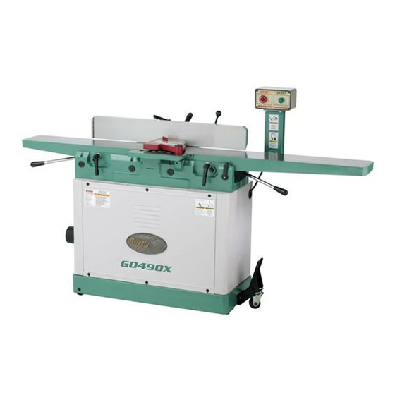
Identification outfeed table Control panel Fence lock outfeed infeed table table infeed table adjustment lever outfeed table infeed table adjustment lever lock Dust port Fence tilt lever tilt plunger tilt lock Fence lock pedal assembly figure 1. g0490/g0490X identification. To reduce the risk of serious injury when using this machine, read and understand... -
Page 6: G0490 Machine Data Sheet
G0490 Machine Data Sheet MACHINE DATA SHEET Customer Service #: (570) 546-9663 · To Order Call: (800) 523-4777 · Fax #: (800) 438-5901 MODEL G0490 8" JOINTER WITH PARALLELOGRAM BEDS Product Dimensions: Weight................................508 lbs. Width (side-to-side) x Depth (front-to-back) x Height............76-3/8 x 23-1/2 x 45-1/2 in. Footprint (Length x Width)....................... - Page 7 Fence Information Fence Length............................. 36 in. Fence Width............................1-1/4 in. Fence Height............................... 5 in. Fence Stops..........................45 and 90 deg. Cutterhead Information Cutterhead Type............................4 Knife Cutterhead Diameter........................... 3-3/16 in. Cutterhead Speed..........................5,350 RPM Knife Information Number of Knives............................. 4 Knife Type..............................
-
Page 8: G0490X Machine Data Sheet
G0490X Machine Data Sheet MACHINE DATA SHEET Customer Service #: (570) 546-9663 · To Order Call: (800) 523-4777 · Fax #: (800) 438-5901 MODEL G0490X 8" JOINTER W/ SPIRAL CUTTERHEAD Product Dimensions: Weight................................508 lbs. Width (side-to-side) x Depth (front-to-back) x Height............76-3/8 x 23-1/2 x 45-1/2 in. Footprint (Length x Width)....................... - Page 9 Fence Information Fence Length............................. 36 in. Fence Width............................1-1/4 in. Fence Height............................... 5 in. Fence Stops..........................45 and 90 deg. Cutterhead Information Cutterhead Type............................Sprial Cutterhead Diameter..........................3-3/8 in. Number of Cutter Spirals..........................4 Number of Indexable Cutters.......................... 40 Cutterhead Speed..........................5350 RPM Cutter Insert Information Cutter Insert Type........................
-
Page 10: Section 1: Safety
SECTION 1: SAFETY For Your Own Safety, Read Instruction Manual Before Operating this Machine The purpose of safety symbols is to attract your attention to possible hazardous conditions. This manual uses a series of symbols and signal words intended to convey the level of importance of the safety messages. - Page 11 Safety Instructions for Machinery DISCONNECTING POWER SUPPLY. Always APPROVED OPERATION. Untrained operators disconnect machine from power supply before can be seriously hurt by machinery. Only allow servicing, adjusting, or changing cutting tools trained or properly supervised people to use (bits, blades, cutters, etc.). Make sure switch is machine.
-
Page 12: Additional Safety Instructions For Jointers
Additional Safety Instructions for Jointers JOINTER KIcKBAcK. "Kickback" is when KIcKBAcK zONE. the "kickback zone" is the workpiece is thrown off the jointer table the path that is in line with the tables. never by the force of the cutterhead, which can stand or allow others to stand in this area result in serious personal injury or property during operation. -
Page 13: Section 2: Circuit Requirements
SEcTION 2: cIRcuIT REQuIREMENTS 220v Single-Phase Power connection Device the type of plug required to connect your machine Operation to power depends on the type of service you cur- rently have or plan to install. We recommend using the plug shown in figure 2. GROUNDED Serious personal injury could occur if you 6-20 RECEPTACLE... -
Page 14: Section 3: Setup
SEcTION 3: SETuP Needed for Setup This machine presents serious injury hazards the following are needed to complete the setup to untrained users. Read process, but are not included with your machine. through this entire manu- al to become familiar with Description the controls and opera- •... -
Page 15: Inventory
Inventory G0490X cutterhead hardware (Not Shown): • Driver Bits torx t20........2 • l-Wrenches torx t20 ......... 2 • Flat hd torx screws t20 M6-1 x 15 ... 3 the following is a description of the main compo- • indexable Carbide inserts 14 x 14 x 2mm .. 5 nents shipped with your machine. -
Page 16: Cleanup
cleanup Gasoline or products with low flash points can The unpainted surfaces of your machine are explode or cause fire if coated with a heavy-duty rust preventative that used to clean machin- prevents corrosion during shipment and storage. ery. Avoid cleaning with This rust preventative works extremely well, but it these products. -
Page 17: Site Considerations
Site considerations Weight Load Physical Environment Refer to the Machine Data Sheet for the weight The physical environment where the machine is of your machine. Make sure that the surface upon operated is important for safe operation and lon- which the machine is placed will bear the weight gevity of machine components. -
Page 18: Assembly
Assembly Motor Mount Brackets to properly prepare your jointer for operation, complete all of the steps in the assembly pro- cedure prior to performing the Test Run on Page 21. To assemble your jointer: With the help of another person, tip the stand shipping box upside down, then open the bottom of the box to expose the top of the stand. - Page 19 10. With the help of another person, place the 14. have another person help you keep the load stand upright. from swaying, and carefully lift the jointer assembly over the stand, aligning the eight 11. attach the dust port to the stand with the pre- mounting holes in the stand with the holes in installed phillip screws and flat washers, as the bottom of the jointer assembly.
- Page 20 17. use the two pre-installed cap screws to install the fence carriage to the rear of the jointer assembly, as shown in figure 13. Mounting Carriage Bolts figure 15. Motor adjustment controls. 19. Wrap the ribbed V-belt around the cutterhead and motor pulleys, as shown in figure 16.
- Page 21 20. loosen the carriage bolts securing the motor mounting brackets (see figure 17), let the motor slide down to tension the V-belt, then The belt guard MuST be installed before retighten the carriage bolts. operating the jointer or else the moving v-belt will be exposed, creating an entangle- ment hazard at the back of the jointer.
- Page 22 When the outfeed table height is correctly set, the knife or insert at top dead center will barely touch the straightedge, as illustrated in The outfeed table MuST be level with figure 22. cutterhead knives or inserts when they are at top dead center (their highest point during —...
-
Page 23: Dust Collection
Dust collection 27. re-install the rear stand panel. 28. Move the fence back as far as you can to make room for the cutterhead guard. 29. insert the cutterhead guard shaft into the extension fence, as shown in figure 25, so DO NOT operate the Model G0490/G0490X the shaft flat is facing the set screw, then without an adequate dust collection system. -
Page 24: Recommended Adjustments
Without resetting the switch, press the on button. the machine should not start. Before starting the jointer, make sure you —if the machine does not start, the stop have performed the preceding assembly button safety feature is working correctly. and adjustment instructions, and you have the test run is complete. -
Page 25: Section 4: Operations
Regardless of the content in this section, repeats Steps 5–8 until satisfied with the Grizzly Industrial will not be held liable for results. accidents caused by lack of training. 10. stops the machine. -
Page 26: Basic Controls
Basic controls fence Movement: the fence has a lock that keeps it in position (see figure 29). to move the fence, loosen the lock and slide the fence where needed. refer to figures 27–30 and the following descrip- tion to become familiar with the functions of the control panel, table controls, and fence controls. -
Page 27: Stock Inspection & Requirements
Stock Inspection & Scrape all glue off the workpiece before • jointing. glue deposits on the workpiece, Requirements hard or soft, will gum up the cutterhead and produce poor results. Remove foreign objects from • follow these rules when choosing and joint- workpiece. -
Page 28: Squaring Stock
Edge Joint on the Jointer: the concave edge of the workpiece is jointed flat with the jointer (see figure 35). Before turning the jointer ON, make sure the outfeed table height is properly set (refer to Setting Outfeed Table height on Page 43 for detailed instructions) to avoid workpiece kickback and to ensure good results. -
Page 29: Surface Planing
Surface Planing To surface plane the workpiece on the joint- DisConnECt JointEr FroM poWEr! the purpose of surface planing on the jointer is to make one face of the workpiece flat (see figures Make sure you read and follow the Safety 37–38). -
Page 30: Edge Jointing
Edge Jointing To edge joint on the jointer: DisConnECt JointEr FroM poWEr! the purpose of edge jointing is to produce a Make sure you read and follow the Safety finished, flat-edged workpiece surface that is suit- Instructions beginning on Page 8 and the able for joinery or finishing (see figures 39–40). -
Page 31: Bevel Cutting
Bevel cutting To bevel cut on the jointer: DisConnECt JointEr FroM poWEr! the purpose of bevel cutting on the jointer is to Make sure you read and follow the Safety cut a specific angle of the workpiece edge (see Instructions beginning on Page 8 and the figures 41–42. -
Page 32: Rabbet Cutting
Rabbet cutting To rabbet cut on the jointer: DisConnECt JointEr FroM poWEr! the purpose of rabbet cutting is to remove a read and understand SEcTION 1: SAfETy, section of the workpiece edge (see figures 43 beginning on Page 8. & 44). When combined with another rabbet-cut edge, the rabbet joints create a simple, yet strong Make sure your stock has been inspected method of joining stock. -
Page 33: Section 5: Accessories
aCCEssoriEs SEcTION 5: AccESSORIES G1753—Jointer Pal Magnetic Knife Jig T21151—8" SELf-TEST hSS System ® ® (for hSS & cobalt Knives) h5143—8" SELf-TEST cobalt System ® G1756—Jointer Pal Magnetic Knife Jig (Includes 1 Set Knife holders & 4 Double- ® (for carbide Knives) Edge hSS "Dispoz-A-Blade"... - Page 34 T20501—face Shield crown Protector 4" G5562—SLIPIT 1 Qt. Gel ® T20502—face Shield crown Protector 7" G5563—SLIPIT 12 oz Spray ® T20503—face Shield Window G2871—Boeshield T-9 12 oz Spray ® G2870—Boeshield T-9 4 oz Spray T20452—"Kirova" Anti-Reflective S. Glasses ® h3788—G96 Gun Treatment 12 oz Spray T20451—"Kirova"...
-
Page 35: Section 6: Maintenance
SEcTION 6: MAINTENANcE cleaning Always disconnect power to the machine before Cleaning the Model g0490/g0490X is relatively performing maintenance. easy. Vacuum excess wood chips and sawdust, failure to do this may and wipe off the remaining dust with a dry cloth. result in serious person- if any resin has built up, use a resin-dissolving al injury. -
Page 36: Section 7: Service
SEcTION 7: SERvIcE review the troubleshooting and procedures in this section to fix or adjust your machine if a problem devel- ops. if you need replacement parts or you are unsure of your repair skills, then feel free to call our technical support at (570) 546-9663. - Page 37 symptom possible Cause possible solution Workpiece stops in 1. outfeed table is set too high. 1. align outfeed table with cutterhead knife at top dead the middle of the center (Page 39). cut. Chipping marks in 1. Knots or conflicting grain direction in wood. 1.
-
Page 38: Cutterhead Knives (G0490)
cutterhead Knives (G0490) Straightedge Outfeed Infeed Inspecting Knife height if your jointer has a knife-style cutterhead, correct knife height is crucial to the proper operation of the jointer and is very important in keeping the knives sharp. if one knife is higher than the others, it will do the majority of the work, and thus, dull much faster than the others. - Page 39 Adjusting/Replacing Knives the Model g0490 comes with set screw and knife lifter assemblies inside the cutterhead that Before adjusting or replacing the knives, the tables are used to adjust the height of the knives (see Must be parallel with each other (refer to check/ figure 56).
- Page 40 loosen the cutterhead gib bolts, starting in rotate the cutterhead to the first knife you the middle, and alternating back and forth started with. tighten all the gib bolts, starting until all of the gib bolts are loose, but not fall- at the ends and working your way to the mid- ing out.
-
Page 41: Cutterhead Inserts (G0490X)
cutterhead Inserts replace the insert so that a fresh cutting edge faces outward. (G0490X) — if all four insert cutting edges have been used, replace it with a new one. always position the reference dot in the same posi- the Model g0490X spiral cutterhead is equipped tion when installing a new insert to aid in with indexable carbide inserts that can be rotated the rotational sequencing. -
Page 42: Checking/Adjusting Table Parallelism
checking/Adjusting rotate the motor pulley so that you can access the cutterhead body with the straight- Table Parallelism edge between the knives/inserts, as shown in figure 61. if the tables are not parallel with the cutterhead or each other, then poor cutting results and kickback Straightedge can occur. -
Page 43: Adjusting Table Parallelism
checking Infeed Table —if the straightedge sits flat against both the infeed and outfeed table, then the tables To check the infeed table parallelism: are parallel. replace the cutterhead guard, fence, and rear stand panel. Follow all the steps for checking the outfeed table parallelism to first make sure that the —if the straightedge does not sit flat against outfeed table is parallel with the cutterhead. - Page 44 Important: The steps below are intended to be place the straightedge in one of the positions shown in figure 62, and adjust the eccentric performed directly after the steps involved in checking the outfeed table parallelism. Do not bushings (a pin-type spanner wrench or small continue until you have performed those steps.
-
Page 45: Setting Outfeed Table Height
Setting Outfeed use the motor pulley to rotate the cutterhead until one of the knives or inserts is at top dead Table height center (its highest point during rotation), as illustrated in figures 68–69. the outfeed table height must be even with the Top Dead top of the cutterhead knives. -
Page 46: Adjusting Infeed Table Stop Bolts
calibrating Depth Tip: Some advanced woodworkers have found that they can virtually eliminate snipe Scale by setting the outfeed table in the following manner: Perform Steps 1–6 above, then lower the outfeed table slightly so the knife/ insert lifts the straightedge slightly off the the depth scale on the infeed table can be cali- table. -
Page 47: Setting Fence Stops
Setting fence Stops To set the 90˚ fence stop: loosen the set screw in the plunger lock col- lar shown in figure 75, and loosen the fence the fence stops simplify the task of adjusting the tilt lock. fence to 45˚ inward, 90˚, and 45˚ outward (135˚). Tools Needed plunger 45°... -
Page 48: Section 8: Wiring
Technical source. Support at (570) 546-9663. The photos and diagrams included in this section are best viewed in color. You can view these pages in color at www.grizzly.com. -46- Model g0490/g0490X (Mfg. since 3/09) -
Page 49: G0490/G0490X Wiring Diagram
wiring diagram G0490/G0490X Wiring Diagram Ground 6-20 Plug (As Recommended) Control Ground Panel 13no (from behind) Contactor 14no Thermal Overload Switch Switch STOP/Reset Ground Magnetic Switch Assembly Motor Ground READ ELECTRICAL SAFETY -47- Model g0490/g0490X (Mfg. since 3/09) ON PAGE 46! -
Page 50: G0490/G0490X Electrical Components
G0490/G0490X Electrical components figure 77. Motor wiring. figure 78. Magnetic switch wiring. figure 79. Control panel wiring. READ ELECTRICAL SAFETY -48- Model g0490/g0490X (Mfg. since 3/09) ON PAGE 46! -
Page 51: Section 9: Parts
SEcTION 9: PARTS Jointer Breakdown 129-1 27 26 G0490 70V2 Cutterhead G0490X Cutterhead -49- Model g0490/g0490X (Mfg. since 3/09) -
Page 52: Jointer Parts List
Jointer Parts List REF PART # DESCRIPTION REF PART # DESCRIPTION P0490001 HANDLE P0490048 SCALE P0490002 STUD P0490049 RIVET P0490003 BUSHING P0490050 INFEED TABLE P0490004 ECCENTRIC SHAFT P0490051 TABLE SHAFT PSS11M SET SCREW M6-1 X 16 P0490052 EXTENSION TABLE PSS14M SET SCREW M8-1.25 X 12 PCAP02M CAP SCREW M6-1 X 20... - Page 53 Jointer Parts List REF PART # DESCRIPTION REF PART # DESCRIPTION PW03M FLAT WASHER 6MM PAW04M HEX WRENCH 4MM PB02M HEX BOLT M6-1 X 12 PAW05M HEX WRENCH 5MM PW01M FLAT WASHER 8MM PAW06M HEX WRENCH 6MM P0490102 TABLE LOCK LEVER PAW08M HEX WRENCH 8MM P0490103...
-
Page 54: Cabinet
cabinet Breakdown 235-2 235-4 235-5 235-1 235-3 238 239 228-1 228-5 228-4 228-2 228-6 225V2 224V2 262A -52- Model g0490/g0490X (Mfg. since 3/09) - Page 55 cabinet Parts List PART # DESCRIPTION PART # DESCRIPTION PS40M PHLP HD SCR M5-.8 X 16 PN06M HEX NUT M5-.8 PW02M FLAT WASHER 5MM PW02M FLAT WASHER 5MM P0490202 REAR PANEL PS06M PHLP HD SCR M5-.8 X 20 PFS02M FLANGE SCREW M6-1 X 12 P0490235 COMPLETE SWITCH ASSEMBLY P0490204...
-
Page 56: Labels
MuST maintain the original location and readability of the labels on the machine. If any label is removed or becomes unreadable, REPLAcE that label before using the machine again. contact Grizzly at (800) 523-4777 or www.grizzly.com to order new labels. -54-... - Page 57 Would you recommend Grizzly Industrial to a friend? _____ Yes _____No Would you allow us to use your name as a reference for Grizzly customers in your area? Note: We never use names more than 3 times. _____ Yes _____No 10.
- Page 58 FOLD ALONG DOTTED LINE Place Stamp Here GRIZZLY INDUSTRIAL, INC. P.O. BOX 2069 BELLINGHAM, WA 98227-2069 FOLD ALONG DOTTED LINE Send a Grizzly Catalog to a friend: Name_______________________________ Street_______________________________ City______________State______Zip______ TAPE ALONG EDGES--PLEASE DO NOT STAPLE...
-
Page 59: Warranty And Returns
WARRANTY AND RETURNS Grizzly Industrial, Inc. warrants every product it sells for a period of 1 year to the original purchaser from the date of purchase. This warranty does not apply to defects due directly or indirectly to misuse, abuse, negligence, accidents, repairs or alterations or lack of maintenance. - Page 60 Buy Direct and Save with Grizzly – Trusted, Proven and a Great Value! ® ~Since 1983~ Visit Our Website Today For Current Specials! ORDER 24 HOURS A DAY! 1-800-523-4777...