Table of Contents
Advertisement
Operator's Manual
CRFIF rSMAN°
10 in. COMPOUND MITER SAW
AND STAND WITH LASER TRAC ®
Model No. 137.212310
CAUTION:
Before using this Miter Saw,
read this manual and follow
all its Safety Rules and
Operating
Instructions
i
:
Sn_ftetlYalt_s_
ruct i° n s
•
Operation
•
Maintenance
•
Parts List
Customer
Help Line
For Technical
Support
1-800-843-1682
Sears
Parts
&
Repair
Center
1-800-488-1222
Sears, Roebuck and Co., Hoffman Estates, IL 60179 USA
Visit our Craftsman website: www.sears.com/craftsman
Part No. 137212310001
Advertisement
Table of Contents

Related Manuals for Craftsman 137.212310


Summary of Contents for Craftsman 137.212310
- Page 1 Safety Rules and • Parts List Operating Instructions Sears Parts & Customer Help Line For Technical Support Repair Center 1-800-843-1682 1-800-488-1222 Sears, Roebuck and Co., Hoffman Estates, IL 60179 USA Visit our Craftsman website: www.sears.com/craftsman Part No. 137212310001...
- Page 2 ONE-YEAR FULL WARRANTY ON CRAFTSMAN TOOL If this Craftsman tool fails due to a defect in material or workmanship within one year from the date of purchase, CALL 1-800-4-MY-HOME® TO ARRANGE FOR FREE REPAIR (or replacement if repair proves impossible).
- Page 3 12. ALWAYS WEAR EYE PROTECTION. Any power GENERAL SAFETY INSTRUCTIONS tool can throw foreign objects into the eyes and BEFORE USING THIS POWER TOOL could cause permanent eye damage. ALWAYS wear Safety Goggles (not that comply with ANSI Safety Safety is a combination of common sense, staying alert standard Z87.1 Everyday eyeglasses and knowing how to use your power tool.
- Page 4 SPECIFIC SAFETY INSTRUCTIONS MAKE SURE the blade is not contacting the workpiece before the switch is turned ON. THIS COMPOUND MITER SAW IMPORTANT: After completing the cut, release DO NOT USE THIN KERF BLADES they can the trigger and wait for the blade to stop before deflect and contact guard and can cause possible returning the saw to the raised position.
- Page 5 ELECTRICAL REQUIREMENTS - cont'd FUSES may "blow" or circuit breakers may trip DOUBLE INSULATED frequently if: a. MOTOR is overloaded - overloading can occur The power tool is double insulated to provide a double if you feed too rapidly or make too many start/ thickness of insulation between you and tool's electrical stops in a short time.
- Page 6 RECOMMENDED ACCESSORIES Supplied Not supplied I_ WARNING I • Use only accessories recommended for this Blade Wrench Adjustable Wrench miter saw. Follow instructions that accompany accessories. Use of improper accessories may cause hazards. • The use of any cutting tool except 10 in. saw Hex Key blades which meet the requirements under recommended accessories...
- Page 7 UNPACKING YOUR MITER SAW Place the saw on a secure stationary work surface. Separate all parts from the packing material. Check IA WARNING I each one with the illustration to make certain all items are accounted for, before discarding any To avoid injury from unexpected starting or packing material.
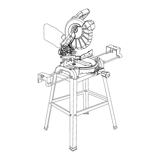
- Page 8 Cutting HeadHandle Upper Blade ON/OFF Trigger S witch Cover DustBac Blade Lower Blade Guard LaserGuide htExtension T able Bevel S cale Hold-down C laml: Positive StopLocking Lever LeftExtension T able Handle Stop Laser On/Off Switch MiterScale Base Wrench Storage ArborLock Latch Table Pivot...
- Page 9 COMPOUND MITER SAW TERMS WRENCH STORAGE - Convenient storage to prevent misplacing the blade wrench. ARBOR LOCK - Allows the user to keep the blade from rotating while tightening or loosening the arbor bolt WOODWORKING TERMS during blade replacement or removal. ARBOR - The shaft on which a blade is mounted.
- Page 10 ASSEMBLY INSTRUCTIONS ASSEMBLE MITER SAW TO STAND Carefully place the miter saw on top of stand. 1,4 WARNING I Line up the four mounting holes in the saw base to the stand. To avoid injury, do not connect this miter saw to the power source until it is completely assembled Fasten the saw to the stand using the four mounting adjusted...
- Page 11 INSTALLING THE MITER HANDLE (FIG. B) Fig, D 1. Thread the miter handle (1) into the hole (2) located at the front of the miter table. Fig, B Locking When transporting or storing the miter saw, the cutting SAW BLADE WRENCH (FIG. C) head should always be locked in the down position.
- Page 12 REMOVING ( FIG.F, G, G-l) NOTE: Pay attention to the pieces removed, noting their 1. Unplug thesawfromtheoutlet. position and direction they face. Wipe the blade collars 2. Allowthemiter sawto risetotheupright p osition. clean of any sawdust before installing the new blade. Raise thelowerbladeguard (1)totheupposition.
- Page 13 INSTALLING THE HOLD-DOWN CLAMP ASSEMBLY Fig. I (FIG. H) 1. Loosen the lock handle knob (3) from the rear side of the saw base (4). 2. Place the hold-down clamp assembly (1) in one of the mounting holes (2). 3. Tighten the knob. IAk WARNING I When using stop block on the right side, hold-down clamp must also be in right side.
- Page 14 Fig. M Cutting head downward travel adjustment (Fig. L) IA. WARNING [ To avoid injury from unexpected starting or electrical shock, turn the switch OFF and remove the power cord from the power source. NOTE: Before each cutting operation, check the position of the blade to make sure it does not contact any metal surface.
- Page 15 MOUNTING THE MITER SAW (FIG. O) Stationary Use To avoid injury from unexpected saw movement: • Before moving the saw, disconnect the power cord from the outlet, and lock the cutting arm in the lower position using the stop latch. NOTE: The stop latch is for carrying or storing the tool.
- Page 16 ALIGNING THE LASER BEAM (FIG. P-l, P-2) screws (1). Start with the set screw on the left side of the laser assembly, then with the front set screw on the I_ WARNING I right side of the laser assembly. For your own safety, never connect the plug to power source outlet until all the adjustment steps Fig.
- Page 17 SAFETY INSTRUCTIONS FOR BASIC SAW missing, bent, damaged or broken in any way, or OPERATION any electrical parts don't work, turn the saw off and unplug it. BEFORE USING THE MITER SAW • Replace bent, damaged, missing or defective parts before using the saw again.
- Page 18 PLANYOUR WORK • Keep the cut off piece free to move sideways after it • Usetherighttool.Don'tforce a toolor attachment is cut off. Otherwise, it could get wedged against the to doa jobit wasnotdesigned t odo.Usea different blade and thrown violently. toolforanyworkpiece t hatcan'tbeheldina solidly •...
- Page 19 BODY AND HAND POSITION (FIG. Q) TURNING SAW ON (FIG. R) WARNING I WARNING Never place hands near the cutting area. Proper Make the switch child-proof. Insert a padlock positioning of your body and hands when through the hole (2) in the trigger switch and lock operating the miter saw will make cutting easier it.
- Page 20 BEVEL CUT (FIG, T) CUTTING BOWED MATERIAL (FIG. V) 1. When a bevel cut is required, loosen the bevel lock A bowed workpiece must be positioned against the handle (1). fence and secured with a clamping device before 2. Tilt the cutting head to the desired angle as shown cutting.
- Page 21 WORKPIECE S UPPORT ( FIG.W) AUXlLARY WOOD FENCE (FIG. X ) Longpieces needextrasupport. T hesupport s houldbe Whenmaking multiple or repetitive c utsthatresult placed under theworkpiece. Keepyourhandholding the cut-off pieces of one inch or less, it is possible for the workpiece positioned 6 -3/4inches or moreawayfrom saw blade to catch the cut-off piece and throw it out of theblade.
- Page 22 CUTTING A DIMENSIONAL 4X4 WITH ONE CUT Fig. AA (FIG. Y) A dimensional 4x4 workpiece (3-1/2 in. x 3-1/2 in. ) may be cut in half with one cut by attaching an auxiliary wood fence of 3/4 inch thick. See "AUXILIARY WOOD FENCE"...
- Page 23 CUTTING CROWN MOLDING (FIG. NOTE: The chart below references a compound BB,CC) cut for crown molding ONLY WHEN THE ANGLE BETWEEN THE WALLS EQUALS EXACTLY 90 °. NOTE: The chart below references a compound cut for crown molding ONLY WHEN THE ANGLE BETWEEN THE WALLS EQUALS EXACTLY 90 °.
- Page 24 protection. Should the lower guard become damaged, MAINTENANCE do not use the saw until the damaged guard has been DANGER I replaced. Develop a regular check to make sure the lower guard is working properly. Clean the lower guard To avoid injury, never put lubricants on the blade of any dust or buildup with a damp cloth.
- Page 25 IA WARNING I To avoid injury from accidental starting, always turn switch OFF and unplug the tool before moving, replacing the blade or making adjustments. TROUBLESHOOTING GUIDE - MOTOR PROBLEM PROBLEM CAUSE SUGGESTED CORRECTIVE ACTION Brake does not Motor brushes not sealed or lightly 1.
- Page 26 MODEL NO. 137.212310 WARNING I When servicing use only CRAFTSMAN replacement parts, Use of any other parts many create a HAZARD or cause product damage. Any attempt to repair or replace electrical parts on this Miter Saw may create a HAZARD unless repair is done by a qualified service technician.
- Page 27 10 in. COMPOUND MITER SAW MODEL NO. 137.212310 SCHEMATIC FOR SAW 0KU_ 2 OKA9 2COF OK_Ke 25TF OJAZ_ 2CS_0JMM _v/_OjTR OKRO 0JZN 2F3M OKQX 2BPW OKDH 2DAS 0824 .2BP5 081A 2DAV...
- Page 28 10 in. COMPOUND MITER SAW MODEL NO. 137.212310 PARTS LIST AND SCHEMATIC FOR MOTOR Size I.D. Description 0HX9 NEEDLE BEARING 0JB8 WAVE WASHER 0JX3 HEX. SOC. SETSCREW 0KCN CR.RE. PAN HEAD TAPPING & WASHER SCREW 0QQS BRUSH HOLDER ASS'Y 0QQT BRUSHASS'Y 0QR0 BRUSH COVER...
- Page 29 10 in. COMPOUND MITER SAW MODEL NO. 137.212310 PARTS LIST AND SCHEMATIC FOR STAND Size I.D. Description 093B FOOT PAD 0J4F FLAT WASHER q_8X] 6-2.5 0KE3 CR. RE. PAN HD. SCREW M8* ] .25-35 0KRR SERRATED TOOTHED HEXAGON FLANGE NUT M8* ] .25 T=7.5 20N0 FOOT PAD ASS'Y...
- Page 30 Your Home For repair - in your home - of all major brand appliances, lawn and garden equipment, or heating and cooling systems, no matter who made it, no matter who sold it! For the replacement parts, accessories owner's manuals that you need to do-it-yourself. For Sears professional installation of home appliances...