
Summary of Contents for Epson Weighing Indicator XK3190-A1+P
- Page 1 XK3190-A1 Weighing Indicator USER’ S GUIDE Attention: Please read this User’s Guide carefully when you use the indicator!
-
Page 2: Specifications
X K 3 1 9 0 - A 1 1 . Specifications 2 . Installation Front & Back View of Indicator Keyboard Function Connecting Loadcell to Indicator 3. Calibration 4. Operating Instructions 4.1 Starting and Starting auto zero setting at turning on 4.2 Manual Zero Setting (Semi-automatically setting zero ) 4.3 Tare Function 4.4 Connecting Scoreboard to Indicator... - Page 3 X K 3 1 9 0 - A 1 Model Sample rated Load cell sensitivity Division Display Clock Scoreboard display interface Communication port Printing Port Power Supply Operating Temperature and Relative Humidity Storage /transportation Temperature Fuse 1 Specification XK3190-A1 5~25 times / sec 1~ 2mv/v 1/2/5/10/20/50/100 optional 7-bits LED digital display 0.56”...
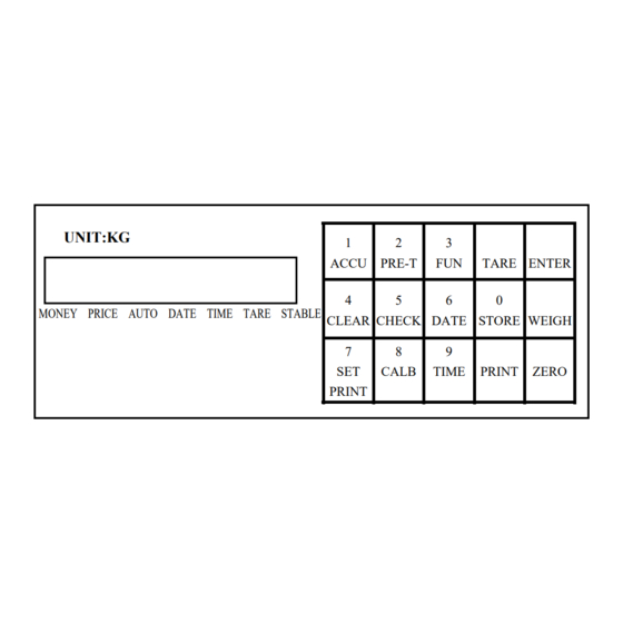
- Page 4 X K 3 1 9 0 - A 1 2.1 Front & Back View of the Indicator UNIT:KG MONEY PRICE AUTO DATE TIME TARE STABLE (Graph 2-1) Front View of Indicator * ACCU - accumulating ( 25 ) pins Print output port Power source (Graph 2-2) Back View of the Indicator 2.
-
Page 5: Keyboard Function
In weighing mode, when stable sign appeares, press [ZERO] key to clear limited weight on the platform. You can set zero range , generally the zero range is 4% of full scale. In weighing mode, when stable sign appears, press [PRINT] key to print weight data. - Page 6 X K 3 1 9 0 - A 1 In calibration or parameters setting mode, pressing [weigh], it will exit from original calibration or setting mode and return to weighing mode. 2.3 Connecting Loadcell to Indicator 1. The 9-pin socket is used for the link-up of loadcell, which has been clearly shown in the graph 2-3.
- Page 7 [ Enter ],will enter into the tenth step. If pressing [ weighting ], Indicator will return to weighing status. Example: 30090 [ noLoAdn] Confirming Zero position. At this time there is no load on the scale.Pressing [Input] when the stable light is on.
- Page 8 After stable light is on, press [ Enter ] key. [ noLoAd ] Confirming zero position again. Reloading weight on scale ≥50% Max. [ ALoAd2 ] It is better that this loading weight is [ 20000 ] near the F.S. Example: 20000 After stable light is on, press [ Enter ] key.
-
Page 9: Operating Instructions
2 When power on, if loading weight on the plat form of the scale deviates from the zero point, but still within zero set range, Then indicator will set zero at power on automatically. - Page 10 X K 3 1 9 0 - A 1 (Graph 4-1) Serial Communication port and score display port 4.4 Connecting Scoreboard to Indicator 1. The display interface of scoreboard is 15-pin socket, which has been clearly shown in the Graph 4-1. The scoreboard signal is 20mA continuous current loop, outputting in binary code, rate is 600.
- Page 11 [ type Selecting type of the printer. 0: print inhibited 1: TPup16TP (Eng. mode) 2: TIMES TM-800 [ type 3 National KX-P1121 4: EPSON LQ-1600K Example: 2 [ H-u Selecting print format 0: Record format 1: document format [ H-u...
- Page 12 X K 3 1 9 0 - A 1 Press[Enter] Note: You can use discount only when the blank filling mode is selected. 4. print and print format Press [PRINT] key, you can print required weighing data according to print setting. Record Format: Time Gross ( kg ) Tare ( kg ) Net ( kg ) Accumulating(kg)
- Page 13 X K 3 1 9 0 - A 1 REMARK ★ If setting the odE parameter to 1, you can perform the blank filling priting, at this time the other priting formats are invalid (Records format and document format are invalid). Method: pushing [print] key, if dct parameter is set to 1, it will display [BFL **], inputting the discount rate and pushing [Input], it will print out the blank filling report: if dct parameter is set to 0, it will print out the blank filling...
- Page 14 X K 3 1 9 0 - A 1 communication mode parameters. (2) The sequence of parameters setting as following: Connecting the loadcell , the indicator enters into working mode which is shown in the Graph 2-3. Insert the setting jumper into 15-pin socket at the back of indicator. (There is a 15-pin plug in the packing carton with its 14-pin shorte connected with 15-pin.
- Page 15 X K 3 1 9 0 - A 1 [ Enter] key or [weighing] key to exit. If it is incorrect, using digital keys enters new date , then press [ Enter ] key. (2) Under weighing status of the indicator, press [ Time ] key, and Time sign lamp is lighted.
- Page 16 X K 3 1 9 0 - A 1 3 Clear Press [ clear ] key, can clean accumulating weight value or stored data. Step Operating press [ Clear ] press [ 1 ] [ sure 1 ] 4.9 Insufficient voltage indicating When the storage cell voltage is insufficient, the insufficient voltage lamp is on.
- Page 17 X K 3 1 9 0 - A 1 electronic components will be damaged and electric shock is likely to happen. 5.6 You should cut off power supply of indicator and relevant device before you pull-in and out the connecting line of indicator and external device. ▲...
- Page 18 It means the load cell signal line is wrongly connected, or its signal is negative. (1) If this scale is under usage , then can be sure : the load cell connecting wires had troubles, or load cell has been damaged.
- Page 19 X K 3 1 9 0 - A 1 3 Err 21 Calibrating data have been lost in RAM and EPROM, Operator must in the calibration plug, then reenter the original calibration data, turn on the indicator again or re-calibrate it. 4 Err 22 EPROM has been damaged.
- Page 20 X K 3 1 9 0 - A 1 The frame from the computer consists of 6 data 02 (X ON) A ~ Z A: Shaking hands B: asking GW C: asking tare D: asking NW E: asking accumulated times and accumulated weight 03 (X OFF) ⊕...
- Page 21 X K 3 1 9 0 - A 1 The explanation of data No : 4 - n Command No data Command + / - GW data (6 bits) GW data Decimal position Command Tare: + / - Tare data Tare data Decimal position Command...
- Page 22 X K 3 1 9 0 - A 1 Command Accumulated times and weigh Accumulated times (4 bits ) , (comma) separation mark Accumulated weight (10 bits ) Decimal position Each frame consists of 22 groups of data...