Table of Contents
Advertisement
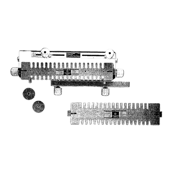
Model No,
171.25450
CRAFT$1VlAK
INDUSTRIAL
DOVETAIL
FIXTURE
• Assembly
• Operation
iMPORTANT;The
followingrouter bits are required
for usewith this fixture:#25414-1/4-in. Straight Router Bit and
#25415-9/16-in. Dovetail Router Bit which are used
for THROUGHor OPENJOINTS.
: #25505 or #26318-1/2-in. Dovetail RouterBit which
are used for a!l HALFBLINDJOINTS.
Readand follow
all instructions
carefully.
KEEP THIS
MANUAL FOR
' FUTURE
REFERENCE,
Sold by Sears, Roebuck and Co,, Hoffman Estates,IL 60179
#
83463
Advertisement
Table of Contents

Summary of Contents for Sears Craftsman 171.25450
- Page 1 CRAFT$1VlAK INDUSTRIAL Model No, DOVETAIL 171.25450 FIXTURE • Assembly • Operation iMPORTANT;The followingrouter bits are required for usewith this fixture:#25414-1/4-in. Straight Router Bit and #25415-9/16-in. Dovetail Router Bit which are used for THROUGHor OPENJOINTS. : #25505 or #26318-1/2-in. Dovetail RouterBit which are used for a!l HALFBLINDJOINTS.
- Page 2 FAILURE TO HEEDALLSAFETY AND OPERATING INSTRUCTIONS ANDWARNINGSREGARDING USEOF THIS PRODUCTCANRESULT IN SERIOUS BODILYINJURY 1) KNOWYOUR POWERTOOL 14) DONOTOVERREACH Read theowner'smanual c arefully. L earnitsapplications and Keepproper f ootingand balance at all times. Iimitatlonsaswell asthe specificpotentialhazards p articularto 15) MAINTAIN TOOLS WITHCARE this tool.
- Page 3 INTRODUCTION Your Sears/Craftsman industrial Dovetail Fixture is an accessory used with your Router to allow you to make drawers, chests, and the like where dovetail joints are used to join the front, back, and sides of the workpiece.
- Page 4 ASSEMBLY INSTRUCTIONS Thefollowing toolsare required for assembly: 1) A mediumsizedPhillips screwdriver, 2) A smallor mediumsizedadjustable wrench. ASSEMBLY OFTHERIGHTSIDETEMPLATE SUPPORT TO THEDOVETAIL BASE 1). Place the dovetailbase topsidedownon a flat surface. 2) insertoneof the5/16-18x 2" long roundheadsquareneckbolts into thes!ot in the rightsideof thebase.(NOTE: Therightsideof the baseis identifiedbythewords RIGHT SIDEmoldedinto it.) 3) Placea 11/32"I.D_x 7/8"O.D.washerontothe bolt asshownin Figure1, 4) Threada 5/16-18hexnut ontothe bolt, asshown,until it bottomsout against t he washer,...
- Page 5 ASSEMBLY OF THETOP CLAMPING BARTO THEDOVETAIL BASE 1) Assemble o ne of the boltsupportsto bothof the 5/16-18X 3-1/2"longroundhead squareneck boltsas shown in Figure 2. 2) Alignthe square on the boltwiththe squareholein the boltsupport.Theboltsupportisto =bottom-out"againstthe bolt asshown in Figure 3. FIG. 2 5/16-18X3-1/2"...
- Page 6 7) Placea springand springretainer, a ssembled in step3, overthe bolt sothespringfits intothe countersink in thethick washer a sshown In Figure6. 8) Pressdownon thespringretaineruntiljust the endof the bolt sticksout pastthe endof the springretainer. 9) Slidethe clampingbaroverthe bolt sothatthe spring retainerabutstheinsideof theclampingbar asshownin figure6. NOTE: T HE SPRING RETAINER M USTPUSH AGAINST THECLAMPNG BAR.
- Page 7 ASSEMBLY OF THEFRONTCLAMPINGBARTO THEDOVETAIL BASE 1) Assemble the front clampingbarto the dovetail b asefollowingthesameprocedure usedto assemble thetop clamping bar tothe dove- tail baseas shown in Figure8. The5/16-18X 4-1/2"long roundheadsquareneckboltsare used, Fig. 8 CLAMPING (SHOWN WITH COMPRESSION END CUTAWAY AND SECTIONED SPRING SO NYLON S PRING RETAINER...
- Page 8 4) Securely tightenthe screw, NOTE: T HENEXT TWOSTEPS ARE PRE-ASSEMBLY STEPS. 5) Sgde theretainerovertheendof thepivotshaftfor about2".Theretainer m ayfit tightly; thisis normal 6) Threadthe#1_`16x1/2"_ngpanheadtappingscrewint_theh_eintheretainerunti_itbott_ms-_tagain_tthepiv_tsha_.(Thescrew will fit tightlyin the hole.) SeeFigure 10. Fig. 10 #!0-16X 1/2"LONG PANHEAD TAPPING SCREW 7) Loosenthescrewaboutone turn. Remove the retainer f rom the shaftandsetit asidetemporarily. 8) Assemble the pivot shaftwith camhandle to the basebyinsertingtheendof thepivot shaftthroughthe holestnthe righttemplate support andthebase.
- Page 9 11) Continue pushingthepivot shaftthroughthe holesand theretaineruntilthe endof the pivotshaftextendsout ofthe left template support asshowin Figure12. 12) Make surethe endof thecam handle fits intothe holein thebaseasshown, Fig. 12 PIVOT, HOLE INBASE, PtVOT S HAFT SUPPORT HANDLE _" 13)With the camhandlepushedin against t he base,positionthe retaineragainst t hesidewallof the base,asshownin Figure 13.Theretainer shouldbarelytouchthesidewall ofthe base.
- Page 10 14) Assemble the othercam handle to theotherendof the pivot shaftusinga 13/64"I,D.x 9/16"O.D,washerand a#10-32 X 5/8"long penhead machinescrew,asshownin Figure14. 15) Makesurethat thecamhandlelinesup with the camhandleat theotherend ofthe pivotshaftandthat theend ofthe camhandlefits into the holein thebase. 16)Tightenthe screwsecurely, LEFT TEMPLATE SUPPORT Fig. 14 #10-32 X5/8"LONG PANHEAD MACHINE...
- Page 11 ASSEMBLY OFTHETOPSTOPBLOCKS TO THEDOVETAIL BASE • Thetop stop blocksareassembled to thetop of thedovetailbasein oneof two waysdepending uponwhich styleof dovetailjoint is to becut: HALF-BLIND FLUSH JOINTS--The "A" on thestop blockfacestowardthe "middleof the base". HALF-BUND RABBET J OINTS_The"B" on thestop blockfacestowardthe"middleof the base". THROUGH J OINTS--The"A"...
- Page 12 •Placethetemplatestiffenerinto therectangular s lot in the underneath s ideof thetemplate, a sshownin Figure 18. NOTE: T HETEMPLATE FORCUTTING HALF-BLIND J OINTS ISBEING USED ASANILLUSTRATION INTHEFOLLOWIHG FIGURES. 1) Threada #8-36x 3/16"long panhead machine screwthrougheachof the fiveholesin thetemplateandinto thethreaded holesin the templatesupport,asshownin Figure24 and securely tightenall of thescrews. Fig.
- Page 13 ALIGNMENTOFTHETEMPLATES In orderfor the Dovetail F ixtureto functionproperly,it is necessary f or thetemplates to bealignedwith respectto dovetailbase. T he reasonfor this, isthat dovetailcutsareat both endsof the Dovetail F ixture. W henproperlyaligned, t he resultbeingall matingcorners will alwaysbe linedup. NOTE: THETEMPLATE F OR CUTTING HALF-BLIND J OINTS IS BEING USED ASANILLUSTRATION IN THEFOLLOWING FIGURES, 1) Withthe dovetailbasesti!l havingthe 1/2"spacingbetween thewasher andthetemplatesupports(Referto Figure17),assemble the templateassembly to thedovetailso that:...
- Page 14 TEMPLATE Fig. 22 _"DISTANCE BETWEEN THESE SURFACES MUST BE EQUAL ATBOTH ENDS TEMPLATE BRACKET CONDITION ONE." TEMPLATE B RACKETS P ROTRUDE B EYOND TEMPLATES TEMPLATE Fig. 23 THESE SURFACES MUST BEEQUAL ATBOTH ENDS TEMPLATE BRACKET CONDITION TWO;TEMPLATE P ROTRUDES BEYOND TEMPLATES BRACKETS MUST BEEQUAL ATBOTH ENDS TEMPLATE BRACKET...
- Page 15 4) After thetemplatebrackets havebeencorrectlypositionedon thetemplatesecurelytightenthefourscrewsholdingthetemptate brackets to thetemplate. 5) Remove thetemplateassembly from the baseandset it asidefor now. 6) Align theothertemplateassembly in thesamemanner, IT SHOULD BENOTED THAT YOUMAYFIND,THAT AFTER MAKING SOME SAMPLE CUTS, S LIGHT ADJUSTMENTS MAYBEREQUIRED. HOW TOMAKETHESE ADJUSTMENTS IS EXPLAINED INTWOOFTHEFOLLOWING SECTIONS: "MAKING ADJUSTMENTS FOR HALF BLIND JOINTS"...
- Page 16 Assembly for other brands of routers: IN ORDER TOUSE THEDOVETAIL FIXTURE W iTHOTHER BRANDS OFROUTERS, IT WILL BENECESSARY FOR YOUTOPURCHASE A CRAFTSMAN U NIVERSAL ROUTER ADAPTER PLATE, M ODEL NO.25326,FROM SEARS, ANDREPLACE T HEBASE PLATE ONYOUR ROUTER WITHTHEADAPTER PLATE. 1) Placethe routerupside on a flat surfaceand remove anyguidebushingthat maycurrentlybe in the router, 2) Placetheguidebushingrequired for thetypeof dovetailjointto be cut underthe routerbaseplateas shownin Figure2&...
- Page 17 4) Positiontheguidebushingsothat thethreethreadedholesin theguidebushinglineup with the countersunk holesin the adapter p late. 5) Threada #10-32x 3/8"long flathead machine screwinto eachon theholes, 6) Securely tightenthescrews. _PLATE Fig. 29 NOTE THEORIENTATION THE GUIDE BUSHING INSTALLATION I NSTRUCTIONS THEDOVETAIL FIXTURE MUSTALWAYS BEFIRMLY ANDSECURELY MOUNTED TOA SOLID ANDFIRM WORK SURFACE, SUCH ASA WORKBENCH, BEFORE U SE.
- Page 18 9) Applying a smallamountof soapto the screwthreads will makeit easierto threadthescrewsintothe holes. 10) Line up thefront of themountingboardwith the front of a workbench or othersturdysurface, 11) Usingtwo clamps,such asC-clamps, f irmly clampthe Dovetail F ixture t o theworkbench byclamping on the mountingboardasshownIn Figure31 and Figure31A.
- Page 19 NOTE: T HENORMAL DEPTH OFCUTFOR A HALF BLINDFLUSH JOINTIS3/8". DRAWERFRONT(PtNPtECE Fig. 32 DRAWER SIDE(TAIL PIECE) SIDE (TAIL PIECE) DRAWER BACK (PiN PIECE) _ HALF BILHD FLUSH JOINT Half BlindFlushOffsetJoint: TheHaftBlind FlushOffsetJoint is usedwhen: Theheightof boththedrawerfront andthe drawerbackis the sameheightasthe drawersides;the tengthof thedrawerfront is 1/8" longer(1/16"on a side)thanthewidth of thedrawer;andthe lengthof thedrawerbackis the sameasthewidth of thedrawer.
- Page 20 Half BlindRabbetedJoint: TheHalfBlindRabbeted Joint is usedwhen: thedrawerfront overlaps the opening for the draweron all four sides of theofthe draweropening (top bottom andtwo sides)that is; thelengthof thedrawerfront is3/4 longer(3/8"on a side)thanthe width of thedrawer;the heightof the drawerfront is also3/4"higher (3/8°on side)thanthe heightof the drawer; t he tengthof the drawerbackis thesameas thewidth of thedrawer;and theheightof the drawerbackis thesameasthe heightof the drawer SeeFigure 34 Toobtainthis joint cut a 3/8"deepby3/8"wide rabbetaroundthe inside periphery of thedrawerfront...
- Page 21 ADJUSTING THEDEPTH-OF-CUT Fig. 36 OFTHEROUTER BIT ALWAYS MAKE SURE THAT THEROUTER IS ROUTER BIT "TURNED OFF"ANDTHAT THEELECTRICAL CORDHAS BEEN UNPLUGGED FROM THEELECTRICAL OUTLET GUIDE BUSHING BEFORE A SSEMBLING ORREMOVING ROUTER BITSTO THEROUTER, • Youwill notethattherearesix pockets along thefront surfaceof thedovetailbase,andthat theyare identified bya dimensions suchas3/8, I/2,-up to 1.
- Page 22 4) Gradually movethe routerbit outward,by usingthe depth-of-cut f eatureon the router, u ntilthetip of the routerbit touchesthe bottomot the pocket, a s shownin Figure37 andFigure37A. 5) Lockthe routerin position, Fig. 38 ?FOOT 6) Thedesireddepth-of-cut h asbeenset. 7) Toset a depth-of-cutNOTprovidedfor on the dovetail b ase,simplypJace theunusedtemplateen the routerbaseplate, as shownin Figure38,Theheightfrom the template to the end or tip of the routerbit will thenbe the requireddepthof cut, WHEN SETTING THE DEPTH OFcuT,MAKE ABSOLUTELY SURE THAT THE COLLET NUT DOES N OT CONTACT (TOUCH) THE GUIDE...
- Page 23 • Theclamping barshavebeen speciallydesigned to allowtheclamping f orcestobeapplied nextto theworkpieces for moreefficient clamping. This isaccomplished bybeingableto positionthe clamping k nobsin close proximityor nextto theworkpieces. • Figure 39 illustrates thepositioning of theclamping barsand theclamping knobswhentheworkpieces are clamped t o the LEFT SIDEof theDovetail F ixture, Figure40 illustrates the positioning of theclampingbarsandtheclamping knobswhentheworkpieces are clamped to the RIGHT SIDEof the Dovetail F ixture.
- Page 24 • Inaddition,thefigure showswherethefour cornersof the drawerarecut on the Dovetail F ixture: CORNERS 1 AND3 arecot on theLEFT SIDEof the Dovetail F ixture, CORNERS 2 AND4 areouton theRIGHT SiDEof the Dovetail F ixture. • Trialcutsare stronglyrecommended u singscrapwoodto ensurethat thefinalworkpiecee are ofthe desiredquaIity, GENERAL PREPARATIONS: a) Theworkpieces comprisingthedrawer, t hat is, front,back,left side,andrightsideshouldbe outto the proper l ength,width, a nd thickness(es),...
- Page 25 e) Assemble the.40"guidebushingto therouterbaseplate, asdescribed in a previous section.Thisthesmallerof thetwo guidebushings furnishedwith this product. f) _nsta__Searsd_vetai_r_uterbit_#255_5_r#26318_t_ther_uterasdescribed_ny_urR__ter_wner_sManuaLShankengagement shouldbe a minimumof 3/4% MAKE SURE THAT THE ROUTER BITtSALIGNED WITH ORCENTERED IN THE HOLE tN THE GUIDE B USHING. TO DOTHIS, LOOSEN SCREWS HOLDtNG BASE PLATE O R ADAPTER PLATE TO ROUTER, CENTER GUIDE B USHING HOLE WITH RESPECT TO ROUTER BtT AND RETtGHTEN...
- Page 26 3) PositionthedrawerRIGHT sideagainstthefront ofthe basesothat thetop surfaceabutstheleft front stop block.THEINSIDE OFTHE DRAWER SIDEFACES AWAY FROM THEFRONT OFTHEBASE. Thewords "INSIDE SURFACE" markedin (d) Inthe Section,GENERAL P REPARATIONS, shouldbevisible. 4) Lineup the workpieees so that theendof the drawersidelinesup with thedrawerfront asshownin Figure44. 5) Securely clamp the drawersideto the base, 6) Securely clampthe drawerfront to thebase.
- Page 27 14) Cutthedovetailby movingthe routerfrom LEFTTORIGHT, with theguidehushingfollowingthetemplate,DONOT FORCE A NYTHING; MOVE THEROUTER IN SLOW ANDSMOOTH FASHION. 15)Toensurea smoothand uniformjoint, retracethe previouscut by movingtherouterfrom RIG HTTOLEFT with theguide bushingagain followingthe template. 16) _ NEVER LIFT THEROUTER UPWARDS W HEN THEROUTER IS ONANDTHEROUTER BITROTATING O RWHENTHEGUIDE BUSHING IS NEAR TOORTOUCHING T HETEMPLATE.
- Page 28 21) Positionthe drawerLEFT sideagainstthefront of the baseso that thetop surfaceabutsthe left front stop block.THEINSIDEOFTHE DRAWER SIDEFACES UP.Thewords "INSIDE SURFACE" markedin (d) in the Section,GENERAL PREPARATIONS, shouIdbevisible. 22) Lineup the workpieces so that the endof the drawersidelinesup with thedrawerbackasshownin Figure47. 23)Continue as in Steps5 through16 above. 24)Afterthe cut hasbeenmade,the workpieces shouldlooklike thoseillustratedin Figure48.
- Page 29 FIG. 50 °A "FACES MfDDLE OF EASE GRADUAtiON TOWARD THE BACK OFTHE BASE FROM THE CENTER GRADUAtiON c) Whencuttingcorners2 and 3;the camhandleis positioned vertically, a sshownin Figure4& d) All otherGENERAL P REPARATIONS arethesameasthoseusedfor "MAKING DRAWERS WITHHALF BLINDFLUSH JOINTS", THEPROCEDURE FOR CUTTING THESE JOINTS ISTHESAME ASTHATUSED FOR "MAKING DRAWERS W ITHHALF BLINDFLUSH JOINTS". After all dovetailcutshavebeenmade,cuta 1/16"deepby3/8"deeprabbeton oppositeendsof thedrawerfront.
- Page 30 b) Theheightof the drawerfrontis 3/4"higherthanthe heightof the drawerbackanddrawersides. IT IS EXTREMELY IMPORTANT THAT THE TEMPLATE B EPROPERLY ALIGNED WHEN MAKING THESE JOINTS, O RELSE, I N ADDITION TOTHEJOINT SPACING NOTBEING EQUAL, A SSHOWN IN FIGURE 55 BELOW, THETOPSURFACES OFTHESIDES, F RONT, ANDBACK WILLNOT"LINE-UP"...
- Page 31 Fig. 53 DRAWER FRONT_ JOINTIS TOO SHALLOW FRONT DRAWER LEF: DRAWER B A Fig. 54 JOINTIS TOO DEEP BACK EXTENDS OUTPAST SIDE DRAWER LEFT DRAWER R A OUTPASTS_E Fig.55 JOINTSPACING IS NOTUNIFORM SPACING LESSTHAN DRAWER B ACK DRAWER B ACKz- L_I_ DRAWER LEFTSIDEj_...
- Page 32 Fig. 58 CORNER#4 SURFACE LINES CORNER#1 UPWITH FRONT PROJECTFRONA_ STOPBLOCKS PROJECT R tGHT SIDE_._ OUTSIDE OF PROJECT SURFACE FRONT STOP BLOCK SIDE PROJECT TAtL_ CORNER#3 CORNER #2 "" PROJECT B ACK MAKINGPROJECTS WITH OPEN(THROUGH)FLUSHJOINTS: • Thethicknessof boththefront andtheback(pin pieces)must be between 3/8" and1". Thethicknessof the sides(tail pieces)mustalso be between 3/8"and1".
- Page 33 CORRECT T HISSITUATION ORPREVENT IT FROMOCCURRING, REPOStTION T HE ROUTER BITIN THE ROUTER. 1/2 DIA.GUtDE BUSHtNG _ SEARS CRAFTSMAN D OVETAtL _ ROUTER BIT#25414 3) Adjust the depth of cut. The depth of cut for an OPENDOVETAILJOINT is equal to the thickness of the mating part, That is: FORCORNER#1 OF THE PROJECTRIGHTSIDE and FORCORNER#4 OF THE PROJECTLEFTSIDE,THE DEPTHOF CUT IS EQUALTO THETHICKNESSOFTHE PROJECTFRONT.
- Page 34 4) Atthis pointit will benecessary foryou to makea top back-upboard.Thereasons for thetop back-up boardareto minimize splintering and to providesupportfor thetemplate. T hetop back-upboardis a scrappieceof woodhavingthefollowingdimensions: LENGTH: 6"to 8",sufficientlengthso that it canclampedbythe topclampingbarand beusedmorethanonce; WIDTH; 2 "widerthanthe widthof the projectsides; THICKNESS: 1/8"to 1/4"thickerthanthethicknessof theprojectsides;this to prevent"ACCIDENTALLY"...
- Page 35 Thewords "OUTSIDE SURFACE" markedin (d) in the Section,GENERAL PREPARATIONS, shouldhavebeenvisiblebefore thefront back-up boardwas put in place. 8) Lineup theworkpieces sothat the endof the projectsideandback-upboardsDine up asshownin Figure58. 9) Securely clampthe projectsideandthe front back-upboardto the front of thebase. 10)Secureiy damp the topback-upboardto the top of the base. 11) Makesurethatthe partsremainlinedup.
- Page 36 NEVER LIFT THEROUTER UPWARDS W HENTHEROUTER IS ONANDTHE ROUTER BITROTATING O RWHEN THEGUIDE BUSHING IS NEAR TOORTOUCHING THETEMPLATE. THISCANCAUSE DAMAGE T OTHEDOVETAIL FIXTURE; ORLOSS OFCONTROL O F THEROUTER WHICH CANRESULT I N SERIOUS BODILY INJURY. 19)Afterthecut hasbeenmade, t he workpieces shouldlooklikethoseillustratedin Figure60. 20) Remove theworkpiece and back-upboardsfrom the Dovetail F ixture.
- Page 37 25) Lightly clamp the back-up board in place. 26) Position the project side against the front of the base so that the top surface abuts the left front stop bIock, The use of a front back-up board at this step is also recommended. It is positioned between the project side and the cIamping bar as shown in Figure 61. The front back-up board is described in Step 7 above.
- Page 38 5) TOCUTCORNER # 1 OFTHEPROJECT F RONT, positionthe top back-upboardon top of thebasesothat it lines upwith the front of the baseand abutsthe lefttop stop blockasshownin figure 63. Fig.83 / TOP BACK UP B OARD TOP OFTHE BASE /'AUXILIARY TEMPLATE SUPPORT /CASNEEOEO, ..
- Page 39 Fig.65 BACK-UP BOARD DOVETAIL C DRAWER BACK 14) Makesurethat thetemplateis flush and parallel w ith theworkpteces dampedto base, F ornarrowprojectfronts(orbacks), t he useof an auxiliarysupportfor the templateis recommended. Its purposeis to aid in supporting the routerwhilecutting,it canbe madefrom a pieceof scrapwood;...
- Page 40 NEVERLIFT THE ROUTERUPWARDSWHENTHE ROUTER IS ON AND THE ROUTERBIT ROTATING OR WHEN THE GUIDEBUSH- ING iS NEARTO OR TOUCHING THE TEMPLATE. 20) After the cut bas been made, the workpiecesshould look like thoseillustrated in Figure 65, 21) Remove the workpiece and back-up boards from the Dovetail Fixture. 22) The back-up boards can be reused if the cut portions of boards are cut off.
- Page 41 Fig. 67 FRONT E XTENDS OUT PAST SIDE JOINT IS TOO SHALLOW PROJECT FRONT__ PROJECT LEFT SlOE / SIDE EXTENDS OUT PAST FRONT PROJECT B ACI__ SIDE EXTENDS OUT PAST FRONT Fi#.68 JOINTIS TOODEEP FRONT E XTENDS OUT PAST SIDE SIDEEXTENDS O UT PASTBACK Fig.
-
Page 42: Parts List
PARTS LIST #171.25450 INDUSTRIAL DOVETAIL FIXTURE KEY OTY PART NO. DESCRIPTION DOVETAIL BASE 29LD-879 29LD-880 DOVETAIL TEMPLATE HALF BLIND JOINT 29LD-8BI DOVETAIL TEMPLATE OPEN (THROUGH) JOINT 29LD-882 TEMPLATE SUPPORT (RIGHT SIDE) 29LD-883 TEMPLATE SUPPORT (LEFT SIDE) 29LD-884 CAM HANDLE 29LD-885 FRONT STOP BLOCK 29LD-886 TOP STOP BLOCK... - Page 45 "/ ® o /_ ® ®...
- Page 46 Notes...
- Page 47 Notes...
- Page 48 IIIII IIit II When corresponding, a lways givethe following 49LD-60 informationas shownin the list. MANUAL 1. The PARTNUMBER 2. The PARTDESCRIPTION Printed in U,S.A. 3. The MODEL#171.25450 9/96 4. The ITEM NAME-iNDUSTRIAL DOVETAIL FIXTURE 29LMD-50...