Table of Contents
Advertisement
Advertisement
Table of Contents

Related Manuals for Asus P5Q3 Deluxe WiFi-AP n


Summary of Contents for Asus P5Q3 Deluxe WiFi-AP n
- Page 1 P5Q3 Deluxe/ WiFi-AP@n...
- Page 2 Product warranty or service will not be extended if: (1) the product is repaired, modified or altered, unless such repair, modification of alteration is authorized in writing by ASUS; or (2) the serial number of the product is defaced or missing.
-
Page 3: Table Of Contents
Welcome! ..................1-1 Package contents ................. 1-1 Special features ................1-2 1.3.1 Product highlights ............1-2 1.3.2 ASUS AI Lifestyle unique features ......... 1-4 1.3.3 ASUS Intelligent Performance and Overclocking features ..........1-8 Chapter 1: Hardware information Before you proceed ..............2-1 Motherboard overview .............. -
Page 4: Contents
Contents 2.5.4 PCI slots ................ 2-17 2.5.5 PCI Express x1 slots ............. 2-17 2.5.6 PCI Express 2.0 x16 slots ..........2-17 2.5.7 Universal PCI Express x16 slot ........2-17 Jumpers ..................2-19 Onboard switches ..............2-21 Connectors ................. 2-22 2.8.1 Rear panel connectors .......... -
Page 5: Notices
Notices Federal Communications Commission Statement This device complies with Part 15 of the FCC Rules. Operation is subject to the following two conditions: • This device may not cause harmful interference, and • This device must accept any interference received including interference that may cause undesired operation. -
Page 6: Safety Information
Safety information Electrical safety • To prevent electrical shock hazard, disconnect the power cable from the electrical outlet before relocating the system. • When adding or removing devices to or from the system, ensure that the power cables for the devices are unplugged before the signal cables are connected. -
Page 7: About This Guide
Refer to the following sources for additional information and for product and software updates. ASUS websites The ASUS website provides updated information on ASUS hardware and software products. Refer to the ASUS contact information. Optional documentation Your product package may include optional documentation, such as warranty flyers, that may have been added by your dealer. -
Page 8: Conventions Used In This Guide
Conventions used in this guide To make sure that you perform certain tasks properly, take note of the following symbols used throughout this manual. DANGER/WARNING: Information to prevent injury to yourself when trying to complete a task. CAUTION: Information to prevent damage to the components when trying to complete a task. -
Page 9: P5Q3 Deluxe/Wifi-Ap@N Specifications Summary
Dual channel memory architecture Supports Intel Extreme Memory Profile (XMP) ® * Refer to www.asus.com or this user manual for the Memory QVL (Qualified Vendors Lists) Expansion Slots 2 x PCI Express 2.0 x16 slots, support ATI CrossFireX™ Technology at x8 speed (PCIe 2.0 x16_1 blue, PCIe 2.0 x16_2 black*) - Page 10 - ASUS WiFi-AP@n - ASUS AI Direct Link ASUS Quiet Thermal Solution: - ASUS Fanless Design: Heat-pipe solution - ASUS Fanless Design: Stack Cool 2 - ASUS Fan Xpert - ASUS Optional Fan for Water-cooling or Passive-Cooling only ASUS Crystal Sound:...
- Page 11 - PCI Express frequency tuning from 100MHz up to 180MHz at 1MHz increment Overclocking Protection: - ASUS C.P.R.(CPU Parameter Recall) Back Panel I/O Ports 1 x PS/2 Keyboard / Mouse combo port 1 x S/PDIF Out (Coaxial + Optical)
- Page 12 P5Q3 Deluxe/WiFi-AP@n specifications summary Support DVD Contents Drivers ASUS PC Probe II ASUS Update ASUS AI Suite Image-Editing Suite Anti-virus software (OEM version) Form Factor ATX Form Factor, 12”x 9.6” (30.5cm x 24.4cm) *Specifications are subject to change without notice.
-
Page 13: Chapter 1: Product Introduction
This chapter describes the motherboard features and the new technologies it supports. Chapter 1: Product introduction... - Page 14 Chapter summary Welcome! ..................1-1 Package contents ................. 1-1 Special features ................1-2 ASUS P5Q3 Deluxe/WiFi-AP@n...
-
Page 15: Welcome
® The motherboard delivers a host of new features and latest technologies, making it another standout in the long line of ASUS quality motherboards! Before you start installing the motherboard, and hardware devices on it, check the items in your package with the list below. -
Page 16: Special Features
Green ASUS This motherboard and its packaging comply with the European Union’s Restriction on the use of Hazardous Substances (RoHS). This is in line with the ASUS vision of creating environment-friendly and recyclable products/packagings to safeguard consumers’ health while minimizing the impact on the environment. -
Page 17: High Definition Audio
Definition Audio, previously codenamed Azalia) CODEC enables high-quality 192KHz/24-bit audio output that simultaneously sends different audio streams to different destinations. You can now talk to your partners on the headphone while playing multi-channel network games. See pages 2-22 and 2-23 for details. ASUS P5Q3 Deluxe/WiFi-AP@n... -
Page 18: Asus Ai Lifestyle Unique Features
802.11b/g standards. With two antennas, you will not suffer from signal loss like before. You can also enjoy the choice to set the device in AP-Mode or Client Mode. Refer to the bundled ASUS WiFi-AP@n manual for more details. -
Page 19: Asus Quiet Thermal Solution
Fanless Design - Stack Cool 2 ASUS Stack Cool 2 is a fan-less and zero-noise cooling solution that lowers the temperature of critical heat generating components. The motherboard uses a special design on the printed circuit board (PCB) to dissipate heat these critical components generate. -
Page 20: Asus Crystal Sound
See page 2-38 for details. Fan Xpert ASUS Fan Xpert intelligently allows users to adjust both the CPU and chassis fan speed according to different ambient temperature, which is caused by different climate conditions in different geographic regions and system loading. -
Page 21: Asus Mylogo3
ASUS Q-Connector ASUS Q-Connector allows you to easily connect or disconnect the chassis front panel cables to the motherboard. This unique module eliminates the trouble of connecting the system panel cables one at a time and avoiding wrong cable connections. -
Page 22: Asus Intelligent Performance And Overclocking Features
ASUS Intelligent Performance and Overclocking features AI Booster The ASUS AI Booster allows you to overclock the CPU speed in Windows environment without the hassle of booting the BIOS. Precision Tweaker 2 Allows the user to adjust the NB Voltage, FSB termination Voltage, CPU PLL Voltage and the DRAM Voltage in 0.02v steps to finetune voltages to achieve the... -
Page 23: Chapter 1: Hardware Information
This chapter lists the hardware setup procedures that you have to perform when installing system components. It includes description of the jumpers and connectors on the motherboard. Chapter 1: Hardware information... - Page 24 Central Processing Unit (CPU) ........... 2-5 System memory ................. 2-12 Expansion slots ................2-15 Jumpers ..................2-19 Onboard switches ..............2-21 Connectors ................. 2-22 Starting up for the first time ............2-38 2.10 Turning off the computer ............2-39 ASUS P5Q3 Deluxe/WiFi-AP@n...
-
Page 25: Before You Proceed
Before you install or remove any component, ensure that the ATX power supply is switched off or the power cord is detached from the power supply. Failure to do so may cause severe damage to the motherboard, peripherals, and/or components. ASUS P5Q3 Deluxe/WiFi-AP@n... -
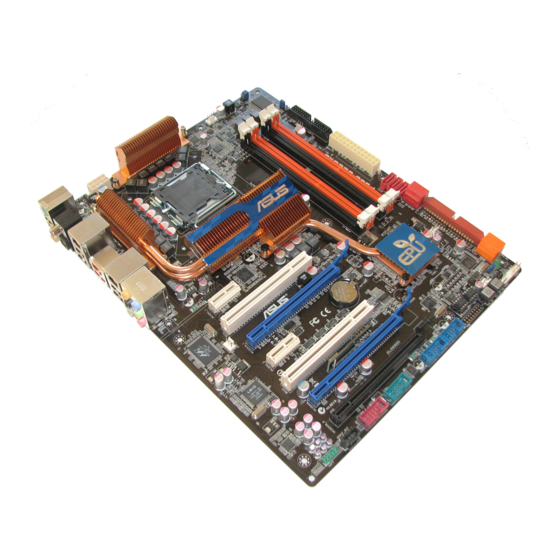
Page 26: Motherboard Overview
Motherboard overview 2.2.1 Motherboard layout Refer to 2.8 Connectors for more information about rear panel connectors and internal connectors. Chapter 2: Hardware information... -
Page 27: Layout Contents
IEEE 1394a port connector (10-1 pin IE1394_2) 2-29 Optical drive audio connector (4-pin CD) 2-34 Front panel audio connector (10-1 pin AAFP) 2-31 Digital audio connector (4-1 pin SPDIF_OUT, for ASUS HDMI 2-35 VGA card) Express_Gate SSD ASUS P5Q3 Deluxe/WiFi-AP@n... -
Page 28: Placement Direction
2.2.3 Placement direction When installing the motherboard, make sure that you place it into the chassis in the correct orientation. The edge with external ports goes to the rear part of the chassis as indicated in the image below. 2.2.4 Screw holes Place nine (9) screws into the holes indicated by circles to secure the motherboard to the chassis. -
Page 29: Central Processing Unit (Cpu)
ASUS will shoulder the cost of repair only if the damage is shipment/transit-related. • Keep the cap after installing the motherboard. ASUS will process Return Merchandise Authorization (RMA) requests only if the motherboard comes with the cap on the LGA775 socket. -
Page 30: Installing The Cpu
2.3.1 Installing the CPU To install a CPU: Locate the CPU socket on the motherboard. Before installing the CPU, make sure that the cam box is facing towards you and the load lever is on your left. Press the load lever with your thumb Retention tab (A), then move it to the left (B) until it is released from the retention tab. - Page 31 The Thermal Interface Material is toxic and inedible. If it gets into your eyes or touches your skin, ensure to wash it off immediately, and seek professional medical help. To prevent contaminating the paste, DO NOT spread the paste with your finger directly. ASUS P5Q3 Deluxe/WiFi-AP@n...
- Page 32 Close the load plate (A), then push the load lever (B) until it snaps into the retention tab. The motherboard supports Intel ® LGA775 processors with the Intel ® Enhanced Memory 64 Technology (EM64T), Enhanced Intel SpeedStep Technology ® (EIST), and Hyper-Threading Technology. Refer to the Appendix for more information on these CPU features.
-
Page 33: Installing The Cpu Heatsink And Fan
Push down two fasteners at a time in a diagonal sequence to secure the heatsink and fan assembly in place. Orient the heatsink and fan assembly such that the CPU fan cable is closest to the CPU fan connector. ASUS P5Q3 Deluxe/WiFi-AP@n... -
Page 34: Uninstalling The Cpu Heatsink And Fan
Connect the CPU fan cable to the connector on the motherboard labeled CPU_FAN. DO NOT forget to connect the CPU fan connector! Hardware monitoring errors can occur if you fail to plug this connector. 2.3.3 Uninstalling the CPU heatsink and fan To uninstall the CPU heatsink and fan: Disconnect the CPU fan cable from the connector on the motherboard. -
Page 35: Installing The Optional Fans
• Plug the optional fan cable to the CHA_FAN1/2 connector on the motherboard. • Make sure the optional fan is installed correctly to prevent damage to the fan and motherboard components. ASUS P5Q3 Deluxe/WiFi-AP@n 2-11... -
Page 36: System Memory
System memory 2.4.1 Overview The motherboard comes with four Double Data Rate 3 (DDR3) Dual Inline Memory Modules (DIMM) sockets. A DDR3 module has the same physical dimensions as a DDR2 DIMM but is notched differently to prevent installation on a DDR2 DIMM socket. DDR3 modules are developed for better performance with less power consumption. -
Page 37: Memory Configurations
• The memory modules may require a better cooling system to work stably under full loading (4 DIMMs) or overclocking setting. ASUS P5Q3 Deluxe/WiFi-AP@n 2-13... -
Page 38: Installing A Dimm
2.4.3 Installing a DIMM Make sure to unplug the power supply before adding or removing DIMMs or other system components. Failure to do so may cause severe damage to both the motherboard and the components. Unlock a DIMM socket by DIMM notch pressing the retaining clips outward. -
Page 39: Expansion Slots
IRQ” or that the cards do not need IRQ assignments. Otherwise, conflicts will arise between the two PCI groups, making the system unstable and the card inoperable. Refer to the table on the next page for details. ASUS P5Q3 Deluxe/WiFi-AP@n 2-15... -
Page 40: Interrupt Assignments
2.5.3 Interrupt assignments Standard interrupt assignments Priority Standard function System Timer Keyboard Controller – Redirect to IRQ#9 Communications Port (COM1)* IRQ Holder for PCI Steering* Floppy Disk Controller Reserved System CMOS/Real Time Clock IRQ Holder for PCI Steering* IRQ Holder for PCI Steering* IRQ Holder for PCI Steering* Reserved Numeric Data Processor... -
Page 41: Pci Slots
PCI Express x1_1 slot Universal PCIe x16_3 slot (black, at max. x4 link) PCI slot 1 PCIe 2.0 x16_2 slot (black, at max. x8 link) PCIe 2.0 x16_1 slot (blue, @x16) PCI slot 2 PCI Express x1_2 slot ASUS P5Q3 Deluxe/WiFi-AP@n 2-17... - Page 42 • In single VGA card mode, use first the PCIe 2.0 x16_1 slot (blue) for a PCI Express x16 graphics card to get better performance. • In CrossFireX™ mode, use the PCIe 2.0 x16_1 (blue) and PCIe 2.0 x16_2 (black) slots for PCI Express x16 graphics cards to get better performance. •...
-
Page 43: Jumpers
• Due to the chipset behavior, AC power off is required to enable C.P.R. function. You must turn off and on the power supply or unplug and plug the power cord before rebooting the system. ASUS P5Q3 Deluxe/WiFi-AP@n 2-19... - Page 44 CPU / Northbridge overvoltage setting (3-pin OV_CPU, 3-pin OV_NB) These jumpers allow you to enable or disable the advanced CPU and Northbridge overvoltage settings in BIOS. Read the following information before you change the jumper settings. Set to pins 1-2 to activate the advanced CPU / Northbridge overvoltage feature.
-
Page 45: Onboard Switches
This is ideal for overclockers and gamers who continually change settings to enhance system performance. Power-on switch Press the power-on switch to wake/power up the system. Reset switch Press the reset switch to reboot the system. ASUS P5Q3 Deluxe/WiFi-AP@n 2-21... -
Page 46: Connectors
Connectors 2.8.1 Rear panel connectors PS/2 keyboard / mouse combo port. This port is for a PS/2 keyboard or a PS/2 mouse. Coaxial S/PDIF Out port. This port connects an external audio output device via a coaxial S/PDIF cable. LAN 2 (RJ-45) port. This Marvell LAN port allows Gigabit connection to a ®... - Page 47 External SATA port. The external SATA port supports external SATA 3.0 Gb/s devices. Longer cables support higher power requirements to deliver signal up to two meters away, and enables improved hot-swap function. ASUS P5Q3 Deluxe/WiFi-AP@n 2-23...
- Page 48 • DO NOT insert a different connector to the external SATA port. • DO NOT unplug the external Serial ATA box when a RAID 0 or RAID 1 is configured. • Before creating a RAID set using Serial ATA hard disks, make sure that you have connected the Serial ATA signal cable and installed Serial ATA hard disk drives;...
-
Page 49: Internal Connectors
Pin 5 on the connector is removed to prevent incorrect cable connection when using a FDD cable with a covered Pin 5. ASUS P5Q3 Deluxe/WiFi-AP@n 2-25... - Page 50 IDE connector (40-1 pin PRI_E IDE) The onboard IDE connector is for the Ultra DMA 133/100/66 signal cable. There are three connectors on each Ultra DMA 133/100/66 signal cable: blue, black, and gray. Connect the blue connector to the motherboard’s IDE connector, then select one of the following modes to configure your device.
- Page 51 Or you may connect the right-angle side of SATA cable to the onboard SATA port to avoid mechanical conflict with huge graphics cards. When using hot-plug and NCQ, set the Configure SATA as in the BIOS to [AHCI]. ASUS P5Q3 Deluxe/WiFi-AP@n 2-27...
- Page 52 SIL5723 Serial ATA connectors [orange] (7-pin SATA_E1-2) These connectors are for the Serial ATA signal cables for Serial ATA hard disk drives. If you installed Serial ATA hard disk drives, you can create a EZ Backup or a Super Speed configuration with the Drive Xpert Technology through the onboard Silicon Image SIL5723 controller.
- Page 53 If your chassis suppots front panel USB ports, you can attach a front panel USB cable to these connectors. Connect the USB cable to ASUS Q-Connector (USB, blue) first, and then install the Q-Connector (USB) to the USB connector onboard.
- Page 54 You can attach a FireWire/1394 cable to this connector if your chassis suppots the front panel IEEE1394 port. Connect the 1394 cable to ASUS Q-Connector (1394, red) first, and then install the Q-Connector (1394) to the 1394 connector onboard.
- Page 55 Front Panel Type item in the BIOS is set to [HD Audio]. If you want to connect an AC' 97 front panel audio module to this connector, set the item to [AC97]. Refer to page 4-26 or details. ASUS P5Q3 Deluxe/WiFi-AP@n 2-31...
- Page 56 • If you are uncertain about the minimum power supply requirement for your system, refer to the Recommended Power Supply Wattage Calculator at http://support.asus.com/PowerSupplyCalculator/PSCalculator. aspx?SLanguage=en-us for details. • If you want to use two or more high-end PCI Express x16 cards, use a PSU with 1000 W power or above to ensure the system stability.
-
Page 57: Power Supply Requirements
Current (A) 6.74 8.92 6.22 6.87 6.52 6.82 Power (W) 81.824 108.913 32.500 23.736 79.544 83.204 SATA-HDD eSATA-HDD IDE-CDROM IDE-HDD Total PSU Voltage (V) 4 Po_max(w) Current (A) 10.45 10.45 12.68 481.970 Power (W) 41.8 10.45 ASUS P5Q3 Deluxe/WiFi-AP@n 2-33... - Page 58 Light Loading Conroe 3.0+EM64T Memory 1 GB*2 8800 Ultra*1 SATA-HDD eSATA-HDD IDE-CDROM IDE-HDD +12V_8Pin +12V_24pin +5V_24pin +3V_24pin +12V_VGA1 +12V_VGA2 +12V_VGA3 Voltage (V) 12.19 12.21 5.22 3.456 12.16 Current (A) 3.19 5.55 5.04 5.36 Power (W) 38.886 67.766 26.309 18.524 79.04 SATA-HDD eSATA-HDD IDE-CDROM IDE-HDD Total PSU Voltage (V) 2...
- Page 59 12. Digital audio connector (4-1 pin SPDIF, for ASUS HDMI VGA card) This connector is for an additional Sony/Philips Digital Interface (S/PDIF) port(s). If you are using ASUS HDMI-equipped graphics card, connect the HDMI card to this connector with a S/PDIF out cable.
-
Page 60: System Panel Connector
14. System panel connector (20-8 pin PANEL) This connector supports several chassis-mounted functions. • System power LED (2-pin PLED) This 2-pin connector is for the system power LED. Connect the chassis power LED cable to this connector. The system power LED lights up when you turn on the system power, and blinks when the system is in sleep mode. -
Page 61: Asus Q-Connector
ASUS Q-Connector (system panel) You can use the ASUS Q-Connector to connect/disconnect chassis front panel cables in a few steps. Refer to the instructions below to install the ASUS Q-Connector. Connect the front panel cables to the ASUS Q-Connector. Refer to the labels on the Q-Connector... -
Page 62: Starting Up For The First Time
Starting up for the first time After making all the connections, replace the system case cover. Be sure that all switches are off. Connect the power cord to the power connector at the back of the system chassis. Connect the power cord to a power outlet that is equipped with a surge protector. -
Page 63: 2.10 Turning Off The Computer
While the system is ON, pressing the power switch for less than four seconds puts the system to sleep mode or to soft-off mode, depending on the BIOS setting. Pressing the power switch for more than four seconds lets the system enter the soft-off mode regardless of the BIOS setting. ASUS P5Q3 Deluxe/WiFi-AP@n 2-39... - Page 64 2-40 Chapter 2: Hardware information...