Table of Contents
Advertisement
Advertisement
Table of Contents

Related Manuals for Asus M4N68T LE V2


Summary of Contents for Asus M4N68T LE V2
- Page 1 M4N68T V2 M4N68T LE V2...
- Page 2 Product warranty or service will not be extended if: (1) the product is repaired, modified or altered, unless such repair, modification of alteration is authorized in writing by ASUS; or (2) the serial number of the product is defaced or missing.
-
Page 3: Table Of Contents
Welcome! ..................1-1 Package contents ................. 1-1 Special features ................1-1 1.3.1 Product highlights ............1-1 1.3.2 Innovative ASUS features ..........1-3 Before you proceed ..............1-4 Motherboard overview ..............1-5 1.5.1 Placement direction ............1-5 1.5.2 Screw holes ..............1-5 1.5.3... - Page 4 Chapter 2: BIOS information Managing and updating your BIOS ..........2-1 2.1.1 ASUS Update ..............2-1 2.1.2 ASUS EZ Flash 2 ............2-2 2.1.3 ASUS CrashFree BIOS 3 ..........2-3 BIOS setup program ..............2-4 2.2.1 BIOS menu screen ............2-5 2.2.3...
- Page 5 Boot Device Priority ............2-18 2.6.2 Boot Settings Configuration .......... 2-18 2.6.3 Security ................. 2-19 Tools menu ................. 2-20 2.7.1 ASUS EZ Flash 2 ............2-20 2.7.2 ASUS O.C. Profile ............2-21 2.7.3 AI NET 2................ 2-21 Exit menu ..................2-22...
-
Page 6: Notices
Complying with the REACH (Registration, Evaluation, Authorisation, and Restriction of Chemicals) regulatory framework, we published the chemical substances in our products at ASUS REACH website at http://csr.asus.com/english/REACH.htm. DO NOT throw the motherboard in municipal waste. This product has been designed to enable proper reuse of parts and recycling. -
Page 7: Safety Information
Safety information Electrical safety • To prevent electric shock hazard, disconnect the power cable from the electric outlet before relocating the system. • When adding or removing devices to or from the system, ensure that the power cables for the devices are unplugged before the signal cables are connected. If possible, disconnect all power cables from the existing system before you add a device. -
Page 8: Conventions Used In This Guide
Refer to the following sources for additional information and for product and software updates. ASUS websites The ASUS website provides updated information on ASUS hardware and software products. Refer to the ASUS contact information. Optional documentation Your product package may include optional documentation, such as warranty flyers, that may have been added by your dealer. -
Page 9: M4N68T V2 Series Specifications Summary
Dual-channel memory architecture Due to CPU spec., AMD 100 and 200 series CPUs support ® up to DDR3 1066MHz. With ASUS design, this motherboard can support up to DDR3 1333MHz. ** Refer to www.asus.com for the latest Memory QVL (Qualified Vendors List). - Page 10 - HT frequency tuning from 200MHz to 300MHz at 1MHz increment - PCIe frequency tuning from 100MHz to 150MHz at 1MHz increment Overclocking protection: - ASUS C.P.R. (CPU Parameter Recall) Other features 100% All High-quality Conductive Polymer Capacitors (M4N68T V2 only) Rear panel ports...
-
Page 11: Chapter 1: Product Introduction
ASUS motherboard Support DVD Documentation User Manual • M4N68T V2 Series motherboards include M4N68T V2 and M4N68T LE V2 two models. The package contents vary from models. • If any of the items is damaged or missing, contact your retailer. - Page 12 Cool ‘n’ Quiet Technology ® This motherboard supports the AMD Cool ‘n’ Quiet technology which ® monitors system operation and automatically adjusts CPU voltage and frequency for a cool and quiet operating environment. Dual-Channel DDR3 1800 (O.C.) support This motherboard supports DDR3 memory that features data transfer rates of 1800 (O.C.)/1600 (O.C.)/1333/1066 MHz to meet the higher bandwidth requirements of the latest operating system, 3D graphics, multimedia, and Internet applications.
-
Page 13: Innovative Asus Features
BIOS file using the bundled support DVD or a USB flash disk that contains the BIOS file. ASUS EZ Flash 2 ASUS EZ Flash 2 allows you to update the BIOS from a USB flash disk before entering the OS. ASUS Q-Fan... -
Page 14: Before You Proceed
This motherboard and its packaging comply with the European Union’s Restriction on the use of Hazardous Substances (RoHS). This is in line with the ASUS vision of creating environment-friendly and recyclable products/packaging to safeguard consumers’ health while minimizing the impact on the environment. -
Page 15: Motherboard Overview
Place six screws into the holes indicated by circles to secure the motherboard to the chassis. DO NOT overtighten the screws! Doing so can damage the motherboard. Place this side towards the rear of the chassis. M4N68T V2 Series ASUS M4N68T V2 Series... -
Page 16: Motherboard Layout
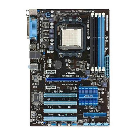
1.5.3 Motherboard layout 20.8cm(8.2in) KBMS KBPWR ATX12V USB34 LAN1_USB12 Lithium Cell CMOS Power AUDIO AAFP PCIEX1_1 M4N68T V2 Series 8211CL PCIEX16 PCIEX1_2 NVIDIA ® PCI1 MCP68 SE Super PCI2 BIOS SPEAKER PCI3 PRI_IDE SB_PWR VT1708S CLRTC PCI4 USBPW5-10 SATA1 SATA2 SATA3 SATA4 USB56... -
Page 17: Layout Contents
CPU into the socket to prevent bending the pins and damaging the CPU! 1.6.1 Installing the CPU To install a CPU: Locate the CPU socket on the motherboard. M4N68T V2 Series M4N68T V2 Series CPU socket AM3 ASUS M4N68T V2 Series... - Page 18 Press the lever sideways to unlock the Socket lever socket, then lift it up to a 90°-100° angle. Ensure that the socket lever is lifted up to a 90°-100° angle; otherwise, the CPU will not fit in completely. Position the CPU above the socket such that the CPU corner with the gold triangle matches the socket corner with a small triangle.
-
Page 19: Installing The Heatsink And Fan
Your boxed CPU heatsink and fan assembly should come with installation instructions for the CPU, heatsink, and the retention mechanism. If the instructions in this section do not match the CPU documentation, follow the latter. Attach one end of the retention bracket to the retention module base. ASUS M4N68T V2 Series... -
Page 20: System Memory
Align the other end of the retention bracket to the retention module base. A clicking sound denotes that the retention bracket is in place. Ensure that the fan and heatsink assembly perfectly fits the retention mechanism module base, otherwise you cannot snap the retention bracket in place. Push down the retention bracket lock on the retention mechanism to secure the heatsink and fan to the module base. -
Page 21: Memory Configurations
• Due to the CPU specification, AMD 100 and 200 series CPUs support up to DDR3 ® 1066MHz. With ASUS design, this motherboard can support up to DDR3 1333MHz. • When overclocking, some AMD CPUs may not support DDR3 1600MHz or higher frequency DIMMs. - Page 22 DDR3-1600(O.C.) MHz capability DIMM support Chip Vendor Part No. Size Chip NO. Brand A-Data AD31600X002GMU 4096MB(Kit of 2) Heat-Sink Package 7-7-7-20 • Corsair CM3X1G1600C9DHX 2048MB(Kit of 2) Heat-Sink Package 9-9-9-24 • • • CRUCIAL BL12864BA1608.8SFB(XMP) 3072MB(Kit of 3) Heat-Sink Package 8-8-8-24 •...
- Page 23 Heat-Sink Package • PATRIOT PSD31G13332H 1024MB Heat-Sink Package • • • Patriot PSD31G13332 1024MB Patriot PM64M8D38U-15 • • Takems TMS1GB364D081-107EY 1024MB Heat-Sink Package 7-7-7-20 • • • Takems TMS1GB364D081-138EY 1024MB Heat-Sink Package 8-8-8-24 • • • ASUS M4N68T V2 Series 1-13...
- Page 24 Dual-channel memory configuration. • C*: Supports two pairs of modules inserted into both the blue and the black slots as two pairs of Dual-channel memory configuration. Visit the ASUS website at www.asus.com for the latest QVL. 1-14 Chapter 1: Product introduction...
-
Page 25: Installing A Dimm
DIMM. Support the DIMM lightly with your fingers when pressing the retaining clips. The DIMM might get damaged when it flips out with extra force. DIMM notch Remove the DIMM from the socket. ASUS M4N68T V2 Series 1-15... -
Page 26: Expansion Slots
Expansion slots In the future, you may need to install expansion cards. The following sub-sections describe the slots and the expansion cards that they support. Unplug the power cord before adding or removing expansion cards. Failure to do so may cause you physical injury and damage motherboard components. -
Page 27: Jumpers
• You do not need to clear the RTC when the system hangs due to overclocking. For system failure due to overclocking, use the CPU Parameter Recall (C.P.R) feature. Shut down and reboot the system so the BIOS can automatically reset parameter settings to default values. ASUS M4N68T V2 Series 1-17... -
Page 28: Usb Device Wake-Up
USB device wake-up (3-pin USBPW1-4, USBPW5-10) Set these jumpers to +5V to wake up the computer from S1 sleep mode (CPU stopped, DRAM refreshed, system running in low power mode) using the connected USB devices. Set these jumpers to +5VSB to wake up the compurer from S3 and S4 sleep modes (no power to CPU, DRAM in slow refresh, power supply in reduced power mode). -
Page 29: Connectors
Mic In Bass/Center Bass/Center Lime (Front panel) – – – Side Speaker Out To configure an 8-channel audio output: Use a chassis with HD audio module in the front panel to support 8-channel audio output. ASUS M4N68T V2 Series 1-19... -
Page 30: Internal Connectors
USB 2.0 ports 1 and 2. These two 4-pin Universal Serial Bus (USB) ports connect to USB 2.0 devices. USB 2.0 ports 3 and 4. These two 4-pin Universal Serial Bus (USB) ports connect to USB 2.0 devices. Serial port. This 9-pin COM1 port is for pointing devices or other serial devices. PS/2 Keyboard port (purple). -
Page 31: Atx Power Connectors
The system may become unstable or may not boot up if the power is inadequate. • If you are uncertain about the minimum power supply requirement for your system, refer to the Recommended Power Supply Wattage Calculator at http://support.asus. com/PowerSupplyCalculator/PSCalculator.aspx?SLanguage=en-us for details. ASUS M4N68T V2 Series... - Page 32 IDE connector (40-1 pin PRI_IDE) The onboard IDE connector is for Ultra DMA 133/100/66 signal cable. There are three connectors on each Ultra DMA 133/100/66 signal cable: blue, black, and gray. Connect the blue connector to the motherboard’s IDE connector, then select one of the following modes to configure your devices: Drive jumper setting Mode of device(s)
- Page 33 XP limitation, Windows XP may not recognize some USB floppy disk ® ® drives. • For more details on RAID/AHCI, refer to the RAID/AHCI Supplementary Guide included in the folder named Manual in the support DVD. ASUS M4N68T V2 Series 1-23...
-
Page 34: Speaker Connector
System panel connector (10-1 pin F_PANEL) This connector supports several chassis-mounted functions. PWR LED PWR BTN F_PANEL PIN 1 M4N68T V2 Series HD_LED RESET M4N68T V2 Series System panel connector • System power LED (2-pin PWRLED) This 2-pin connector is for the system power LED. Connect the chassis power LED cable to this connector. -
Page 35: Digital Audio Connector
Ensure that the audio device of Sound playback is VIA High Definition Audio (the name may be different based on the OS). Go to Start > Control Panel > Sounds and Audio Devices > Sound Playback to configure the setting. The S/PDIF module is purchased separately. ASUS M4N68T V2 Series 1-25... - Page 36 DO NOT forget to connect the fan cables to the fan connectors. Insufficient air flow inside the system may damage the motherboard components. These are not jumpers! DO NOT place jumper caps on the fan connectors. Only the 4-pin CPU fan supports the ASUS Q-Fan feature. 1-26 Chapter 1: Product introduction...
-
Page 37: Software Support
The contents of the Support DVD are subject to change at any time without notice. Visit the ASUS website at www.asus.com for updates. To run the Support DVD Place the Support DVD into the optical drive. - Page 38 1-28 Chapter 1: Product introduction...
-
Page 39: Chapter 2: Bios Information
BIOS in the future. Copy the original motherboard BIOS using the ASUS Update utility. 2.1.1 ASUS Update The ASUS Update is a utility that allows you to manage, save, and update the motherboard BIOS in Windows environment. ®... -
Page 40: Asus Ez Flash 2
Follow the onscreen instructions to complete the updating process. 2.1.2 ASUS EZ Flash 2 The ASUS EZ Flash 2 feature allows you to update the BIOS without using an OS-based utility. Before you start using this utility, download the latest BIOS file from the ASUS website at www.asus.com. -
Page 41: Asus Crashfree Bios 3
2.1.3 ASUS CrashFree BIOS 3 ASUS CrashFree BIOS 3 is an auto recovery tool that allows you to restore the BIOS file when it fails or gets corrupted during the updating process. You can restore a corrupted BIOS file using the motherboard support DVD or a USB flash drive that contains the BIOS file. -
Page 42: Bios Setup Program
• The BIOS setup screens in this chapter are for reference only. They may not exactly match what you see on your screen. • Visit the ASUS website at www.asus.com to download the latest BIOS file for this motherboard. Chapter 2: BIOS information... -
Page 43: Bios Menu Screen
At the bottom right corner of a menu screen are the navigation keys for that particular menu. Use the navigation keys to select items in the menu and change the settings. Some of the navigation keys differ from one screen to another. ASUS M4N68T V2 Series... -
Page 44: Menu Items
2.2.4 Menu items The highlighted item on the menu bar displays the specific items for that menu. For example, selecting Main shows the Main menu items. The other items (Advanced, Power, Boot, Tools, and Exit) on the menu bar have their respective menu items. -
Page 45: Main Menu
Enables or disables the onboard IDE port. Configuration options: [Disabled] [Enabled] Serial-ATA Devices [SATA1,2,3,4] Enables or disables the SATA port. Configuration options: [Disabled] [SATA 1,2] [SATA1,2,3,4] nVidia RAID Function [Disabled] Enables or disables the nVidia RAID function. Configuration options: [Disabled] [Enabled] ASUS M4N68T V2 Series... - Page 46 2.3.4 Primary IDE Master/Slave, SATA 1/2/3/4 While entering Setup, the BIOS automatically detects the presence of IDE/SATA devices. There is a separate submenu for each IDE/SATA device. Select a device item then press <Enter> to display the IDE/SATA device information. The BIOS automatically detects the values opposite the dimmed items (Device, Vendor, Size, LBA Mode, Block Mode, PIO Mode, Async DMA, Ultra DMA, and SMART monitoring).
-
Page 47: System Information
The items and configuration options in this menu may vary depending on the AMD CPU type. CPU Overclocking [Auto] Selects the CPU overclocking options to achieve desired CPU internal frequency. Configuration options: [Manual] [Auto] [Standard] [Overclock Profile] ASUS M4N68T V2 Series... - Page 48 The following item only appears when you set CPU Overclocking to [Manual]. CPU Frequency (MHz) [200.0] Sets the CPU frequency. Configuration options: [200.0] [201.0] [202.0] [203.0] ~ [300.0] The following item only appears when you set CPU Overclocking to [Overclock Profile]. Overclock Options [Overclock 5%] Selects the overclocking profile.
- Page 49 Configuration options: [Auto] [4 CLK] ~ [7 CLK] tWRWR [Auto] Configuration options: [Auto] [3 CLK] ~ [10 CLK] tRDRD [Auto] Configuration options: [Auto] [3 CLK] ~ [10 CLK] tRFC0/1/2/3 [Auto] Configuration options: [Auto] [90ns] [110ns] [160ns] [300ns] [350ns] ASUS M4N68T V2 Series 2-11...
-
Page 50: Cpu Configuration
® [Disabled] ASUS Core Unlocker [Disabled] Enables the ASUS Core Unlocker to get the full computing power of the processor. Select [Disabled] to disable this function. Configuration options: [Enabled] [Disabled] CPU Core Activation [Auto] Allows you to set the active CPU cores. Configuration options: [Auto] [Manual] The following items appear only when you set CPU Core Activation to [Manual]. -
Page 51: Ecc Configuration
MAC LAN [Auto] Enables or disables the onboard LAN controller. Configuration options: [Auto] [Disabled] OnBoard LAN Boot ROM [Disabled] This item appears only when the MAC LAN item is set to [Auto]. Configuration options: [Disabled] [Enabled] ASUS M4N68T V2 Series 2-13... -
Page 52: Onboard Devices Configuration
2.4.4 Onboard Devices Configuration Serial Port1 Address [3F8/IRQ4] Allows you to select the Serial Port1 base address. Configuration options: [Disabled] [3F8/IRQ4][2F8/IRQ3] [3E8/IRQ4] [2E8/IRQ3] Parallel Port Address [378] Allows you to select the Parallel Port base addresses. Configuration options: [Disabled] [378] [278] [3BC] Parallel Port Mode [Normal] Allows you to select the Parallel Port mode. -
Page 53: Usb Mass Storage Device Configuration
Sets the maximum time that the BIOS waits for the USB storage device to initialize. Configuration options: [10 Sec] [20 Sec] [30 Sec] [40 Sec] Emulation Type [Auto] Allows you to set the emulation type. Configuration options: [Auto] [Floppy] [Forced FDD] [Hard Disk] [CDROM] ASUS M4N68T V2 Series 2-15... -
Page 54: Power Menu
Power menu The Power menu items allow you to change the settings for the Advanced Configuration and Power Interface (ACPI) and the Advanced Power Management (APM). Select an item then press <Enter> to display the configuration options. M4N68T V2 BIOS Setup Version 0301 Main Advanced... -
Page 55: Hw Monitor Configuration
CPU Q-Fan Function [Enabled] Enables or disables the ASUS Q-Fan feature that smartly adjusts the CPU fan speeds for more efficient system operation. Configuration options: [Disabled] [Enabled] The following item appears only when you set CPU Q-Fan Function to [Enabled]. -
Page 56: Boot Menu
Configuration options: [Removable Dev.] [Hard Drive] [ATAPI CD-ROM] [Disabled] • To select the boot device during system startup, press <F8> when ASUS logo appears. • To access Windows OS in Safe Mode, do any of the following: Press <F5>... -
Page 57: Security
View Only allows access but does not allow change to any field. Limited allows changes only to selected fields, such as Date and Time. Full Access allows viewing and changing all the fields in the Setup utility. ASUS M4N68T V2 Series 2-19... -
Page 58: Tools Menu
2.7.1 ASUS EZ Flash 2 Allows you to run ASUS EZ Flash 2. When you press <Enter>, a confirmation message appears. Use the left/right arrow key to select between [Yes] or [No], then press <Enter> to confirm your choice. See section 2.1.2 for details. -
Page 59: Asus O.c. Profile
• Only the CMO file can be loaded. 2.7.3 AI NET 2 Check Realtek Phy LAN cable [Disabled] Enables or disables checking of the Realtek LAN cable during the Power-On Self-Test (POST). Configuration options: [Disabled] [Enabled] ASUS M4N68T V2 Series 2-21... -
Page 60: Exit Menu
Exit menu The Exit menu items allow you to load the optimal or failsafe default values for the BIOS items, and save or discard your changes to the BIOS items. Version 0301 M4N68T V2 BIOS Setup Main Advanced Power Boot Tools Exit Exit Options... -
Page 61: Asus Contact Information
+1-510-739-3777 +1-510-608-4555 Web site usa.asus.com Technical Support Telephone +1-812-282-2787 Support fax +1-812-284-0883 Online support support.asus.com ASUS COMPUTER GmbH (Germany and Austria) Address Harkort Str. 21-23, D-40880 Ratingen, Germany +49-2102-959911 Web site www.asus.de Online contact www.asus.de/sales Technical Support Telephone (Component) +49-1805-010923*...