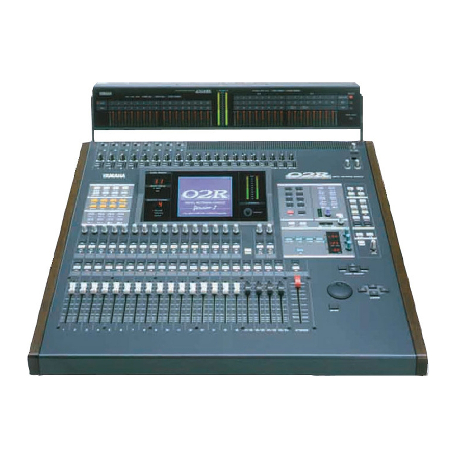
Yamaha 02R Version 2 Manual
Digital recording console
Hide thumbs
Also See for 02R Version 2:
- Application manual (89 pages) ,
- Owner's manual (354 pages) ,
- Installation manual (14 pages)
Table of Contents
Advertisement
Quick Links
Download this manual
See also:
Owner's Manual
Advertisement
Chapters
Table of Contents

Related Manuals for Yamaha 02R Version 2


Summary of Contents for Yamaha 02R Version 2
- Page 1 DIGITAL RECORDING CONSOLE...
- Page 2 FCC INFORMATION (U.S.A.) 1. IMPORTANT NOTICE: DO NOT MODIFY THIS UNIT! This product, when installed as indicated in the instructions contained in this manual, meets FCC requirements. Modifications not expressly approved by Yamaha may void your authority, granted by the FCC, to use the product. 2.
- Page 3 Important Information Important Information Please read the following before operating your 02R Digital Recording Console. Precautions Installing the 02R • The unit should be connected only to an AC receptacle of the type described in the owner’s manual or as marked on the unit. •...
- Page 4 Important Information • When you remove the power plug, be sure to hold the plug. Never pull on the cord. Otherwise, the power cord will become damaged, resulting in fire or electrical shock. • When relocating the 02R, since the 02R is heavy, make sure that two or more people carry it.
- Page 5 Important Information If an abnormality occurs while operating the 02, remove the plug from the AC outlet • If you notice any abnormality—such as smoke, odor, noise, etc—turn off the power to the 02R immediately, and remove the power plug from the AC outlet.
- Page 6 Important Information Influences on other electrical devices This equipment uses many digital circuits, which may cause noise to occur on nearby radio or TV. In this case, relocate the 02R away from those devices. 02R Exclusion of Certain Responsibility Manufacturer, importer, or dealer shall not be liable for any incidental damages including injury to the person, and/or any other damages caused by improper use or operation of the 02R.
- Page 7 DIGITAL RECORDING CONSOLE Getting Started Guide...
-
Page 8: Table Of Contents
Contents Contents Introduction to the 02R..... . 1 02R ........... . . 2 User Guides . - Page 9 Contents Mixing and Automix..... . . 67 What is 02R Automix? ........68 Real-time Automix .
-
Page 10: Introduction To The 02R
Introduction to the 02R Introduction to the 02R In this chapter... 02R ............2 User Guides . - Page 11 Introduction to the 02R From the company that pioneered digital mixing consoles and leads the industry with its acclaimed DSP technology comes the 02R Digital mixing Console—the most advanced digital mixing console in the world. All of Yamaha’s experience and innovation has been applied to the 02R, to create a perfect mixer for use with the current generation of modular digital multitrack tape and disk recorders.
-
Page 12: User Guides
Introduction to the 02R RISC Technology To provide powerful system control and full dynamic automix, the 02R is driven by a RISC technology CPU. With all this power and sonic quality, the 02R will become the heart of your digital recording studio. User Guides The 02R is supplied with an Owner’s Manual that consists of two guides—a Getting Started Guide and a User’s Guide. -
Page 13: Top And Rear Panels
Introduction to the 02R Top and Rear Panels +48V +48V +48V +48V +48V +48V +48V +48V T/B LEVEL 20dB 20dB 20dB 20dB 20dB 20dB 20dB 20dB 20dB 20dB 20dB 20dB 20dB 20dB 20dB 20dB GAIN GAIN GAIN GAIN GAIN GAIN GAIN GAIN GAIN... -
Page 14: Features
Introduction to the 02R Features Sonic Specifications • Linear 20-bit 64-times oversampling A/D convertors • Linear 20-bit 8-times oversampling D/A convertors • 105 dB dynamic range (typical) • 32-bit precision internal processing with a dynamic range of over 190 dB using Yamaha’s 32-bit proprietary audio DSP General Features •... - Page 15 Introduction to the 02R • 2 analog stereo outputs • 6 analog auxiliary send outputs • Stereo studio and control room outputs • 3 digital 2TR IN inputs • 2 digital stereo outputs • Industry standard AES/EBU or IEC958 Part2 (Consumer) digital inputs and outputs •...
-
Page 16: Key Features
Introduction to the 02R Key Features This section looks at some of the key features of the 02R, what they mean to you, and some hints about how you can use them. Dynamic Automix One of the most demanding jobs of the recording engineer is taking all the raw material produced during a multitrack recording session and mixing it all together into an artistically satisfying master recording. - Page 17 Introduction to the 02R Recalling the scene is even easier—just press the [RECALL] button. You should be careful that your scene memories flow into each other smoothly. The instant recall means that you can have very abrupt level changes or the unexpected intrusion of a very loud channel.
-
Page 18: Motorized Faders
Introduction to the 02R current channel. You can customize your 02R to automatically select the corresponding display pages when you adjust a control in these blocks. Motorized Faders In addition to the DISPLAY ACCESS and SELECTED CHANNEL controls, each input channel and the stereo master channel utilizes a 100 mm motorized fader. - Page 19 Introduction to the 02R domain. The dynamics program settings are stored in the dynamics library. There are 40 preset programs for you to recall and 88 user programs for you to store your own dynamics programs Parametric EQ with Library The 02R contains a high-performance four-band, fully parametric EQ.
- Page 20 Introduction to the 02R 02R Sonic Performance The 02R uses linear 20-bit 64-times oversampling analog-to-digital converters to provide a typical dynamic range of 105 dB. This means that an audio program’s dynamic range, from low to high levels, is processed intact.
-
Page 21: Getting Started
Getting Started Getting Started In this chapter... Basic Assumptions..........14 Making the Connections. -
Page 22: Basic Assumptions
Getting Started Basic Assumptions The 02R was designed to be the perfect digital mixing console for a studio using the current generation of modular digital multitrack tape and disk recorders. Although the 02R can also be used as a sound-reinforcement mixer, the typical user will own a project recording or post-production studio with some form of multitrack recorder. -
Page 23: Basic Setup
Getting Started Basic Setup The following illustration shows how to set up a minimal system that will allow you to perform the following tutorials. Amplifier Sound Source Multitrack recorder 02R Getting Started Guide... -
Page 24: Power On/Off
Getting Started Power ON/OFF This section explains how to power the 02R on and off. Power ON It is always important to observe the correct order for powering up equipment in a studio. Always start with the multitrack and mastering recorders and the signal processors, then the 02R, and finally the monitoring amplifiers and other downstream gear. -
Page 25: Recall Scene Memory 0
Getting Started Recall Scene Memory 0 Before you start the tutorials, you should set the 02R to its initial mixer settings. 1. Use the SCENE MEMORY increment or decrement buttons to select scene memory 0 “0 Initial Data”. 2. Press the [RECALL] button. STORE RECALL This is a read-only scene memory that contains the default settings for the... -
Page 26: Introductory Recording Tutorial
Introductory Recording Tutorial Introductory Recording Tutorial In this chapter... Setting the Input Level ......... . 20 Applying EQ . -
Page 27: Setting The Input Level
Introductory Recording Tutorial Setting the Input Level Assuming that the 02R is powered ON and your music source is playing, the very first thing you need to do is set up a basic control room monitor mix. When you recall Scene Memory 0 “0 Initial Data”, all the channel faders are set to the 0 dB mark. - Page 28 Introductory Recording Tutorial Setting the GAIN 1. Use the [METER] button to locate the METER 1/3 page. The MIC/LINE 1 signal is metered. METER 2. If the sound is distorted, the PEAK indicator is illuminated, or the level is going up to CLIP , press the 20 dB (pad) switch to attenuate 20dB the input signal for MIC/LINE 1.
- Page 29 Introductory Recording Tutorial Back off the GAIN control a little until the PEAK indicator illuminates very occasionally. The GAIN control should be set with some care. If it is set too low, the signal-to-noise performance will suffer, and if it is set too high, signal clipping and distortion may occur.
- Page 30 Introductory Recording Tutorial The peak level is indicated by an empty square box. Peak Hold is very useful for level checking before recording. You can leave a mix to play through unattended while Peak Hold watches out for signal peaks. If any levels reach CLIP, back off the relevant GAIN control or use the /ATT display function to attenuate the signal and run through the mix again.
-
Page 31: Applying Eq
Introductory Recording Tutorial Applying EQ The next step is to apply EQ to MIC/LINE 1. Each 02R channel features a four-band fully parametric EQ, with variable bandwidth (Q), frequency (F), and gain (G). The power of the 02R user interface means that there are two ways of adjusting the EQ for MIC/LINE 1. - Page 32 Introductory Recording Tutorial The EQ 1/2 page appears, showing the EQ curve and settings for MIC/LINE 1. 3. Use the CURSOR buttons to select the EQ ON icon. If the EQ is ON, the icon will be highlighted. The LED inset in the [EQ ON] button of the SELECTED CHANNEL—EQUALIZER block controls will also be illuminated.
- Page 33 Introductory Recording Tutorial The gain increases in 0.5 dB steps and the EQ curve on the EQ page changes to reflect this. 3. Rotate the encoder wheel counterclockwise to reduce the gain. The gain decreases in 0.5 dB steps. Alternatively, you could use the EQUALIZER G control. 4.
- Page 34 Introductory Recording Tutorial Setting the Frequency 1. Select the frequency (F) icon for the LOW band using the CURSOR buttons. 2. Use the encoder wheel to sweep through the frequency range. Alternatively, you could use the EQUALIZER F control. All four bands of the 02R parametric EQ cover virtually the entire audio spectrum, from 21 Hz to 20.1 kHz.
- Page 35 Introductory Recording Tutorial Setting the Bandwidth The L-MID and H-MID bands are peaking type EQs. The LOW and HIGH bands are initially configured as shelving type EQs, however, they can also be configured as peaking type EQs. The LOW band can also be configured as a HPF (high-pass filter) and the HIGH band as a LPF (low-pass filter).
- Page 36 Introductory Recording Tutorial Resetting the EQ 1. Press and hold the [LOW/HPF] button and then press the [HIGH/LPF] button of the SELECTED CHANNEL—EQUALIZER controls. All EQ values will be reset to their initial values. LOW/HPF L-MID H-MID HIGH/LPF LOW SHELF Peak –...
-
Page 37: Using The Eq Library
Introductory Recording Tutorial Using the EQ Library The EQ Library is used to access and store EQ settings—stored as programs. There are 32 preset programs (1 to 32) for you to recall and 96 user programs (33 to 128 plus UNDO) for you to store your own EQ settings. - Page 38 Introductory Recording Tutorial The EQ program is recalled. The EQ curve for MIC/LINE 1 is set accordingly. The EQ curve at the top of the display is updated. Your sound source is modified by the program you recalled. If the sound doesn’t change, check if you have left the EQ ON switch turned OFF on the EQ 1/2 page.
- Page 39 Introductory Recording Tutorial Storing an EQ Program 1. Use the [EQ] button to locate the EQ 2/2 page shown below. 2. Select the STORE icon with the CURSOR buttons. In order to scroll through the list of EQ programs, the cursor must be on the STORE, RECALL, CLEAR, COPY, or PASTE icons.
- Page 40 Introductory Recording Tutorial 5. Select the individual character positions with the CURSOR buttons and rotate the encoder wheel to select the characters. You can create a name of up to 16 characters long. It can contain any of the following characters: “...
- Page 41 Introductory Recording Tutorial CANCEL is the default. To cancel the STORE operation, either press the [ENTER] button or wait about 10 seconds—the STORE operation will be automatically cancelled. To store your settings, use the CURSOR buttons to select the “EXECUTE” icon and press the [ENTER] button.
-
Page 42: Routing
Introductory Recording Tutorial Routing This tutorial assumes you have a multitrack recorder and you have connected it to your 02R—after having one or more of the optional input/output cards installed: • Alesis ADAT (CD8-AT)—This single slot card supports an 8-channel ADAT compatible modular digital multitrack recorder. - Page 43 Introductory Recording Tutorial Using the ROUTING Display Function There are two ways to operate the Routing function. One method is to use the ROUTING 1/2 page. The more convenient method is to use the buttons of the ROUTING block of the SELECTED CHANNEL controls. DIRECT ROUTING Note: You can customize the 02R so that when you press a button in the...
- Page 44 Introductory Recording Tutorial Selecting the Routing 1. Use the [ROUTING] button to locate the ROUTING 1/2 page shown below. ROUTING 2. Use the ROUTING buttons of the SELECTED CHANNEL controls to route the MIC/LINE 1 channel. As you press the ROUTING buttons, the LED inset in the button illuminates and the corresponding icon on the ROUTING page appears highlighted.
-
Page 45: Panning
Introductory Recording Tutorial Panning There are two ways to use the Pan function. One method is to use the PAN 1/1 page. The more convenient method is to use the buttons and controls of the PAN block of the SELECTED CHANNEL controls. L/ODD R/EVEN EVEN... - Page 46 Introductory Recording Tutorial Ganging Pans You can gang the pan controls of two adjacent channels for simultaneous pan adjustment 1. Press the [SEL] button for MIC/LINE 1. You can also select the MIC/LINE 1 icon using the CURSOR buttons. 2. Press the [ENTER] button to connect the channels together. You can also gang channels together by simultaneously pressing the [L/ODD] and [R/EVEN] buttons of the PAN block of the SELECTED CHANNEL group.
-
Page 47: Secondary Recording Tutorial
Secondary Recording Tutorial Secondary Recording Tutorial In this chapter... Aux Sends ........... . . 42 Setting the Aux Send Level . -
Page 48: Aux Sends
Secondary Recording Tutorial Aux Sends The 02R has eight aux sends. AUX 7 and AUX 8 are used to feed the internal effects processors, with the signal remaining entirely in the digital domain. The other auxiliary sends—AUX 1 through AUX 6—can be used to feed external signal processors and effects units, foldback amplifiers, or multitrack recording equipment. -
Page 49: Setting The Aux Send Level
Secondary Recording Tutorial Setting the Aux Send Level In this tutorial, MIC/LINE 1 channel is sent to AUX 1. 1. Press the [AUX 1] button. The AUX 1 1/1 page shown below appears. AUX 1 The faders change from channel level controls to aux send level controls. To FADER STATUS INPUT indicate the change, the AUX LED of the FADER STATUS indicator... - Page 50 Secondary Recording Tutorial 4. To change the signal level, adjust the fader for MIC/LINE 1 until the desired value is obtained. You can use the rotary encoders for the tape returns or press the [FLIP] button. Then the tape return channels can be operated by the faders. The effect returns can only be adjusted with the rotary encoders.
-
Page 51: Creating A Monitor Mix
Secondary Recording Tutorial Creating a Monitor Mix The 02R has two different monitoring outputs—the control room outputs and the studio outputs—plus, of course, the PHONES output (which is a duplicate of the control room output). During a multitrack recording session, what you want to listen to in the control room is often very different from what the musicians need in the studio. -
Page 52: Applying Effects
Secondary Recording Tutorial Applying Effects The 02R features two internal multi-effects stereo processors: Effect 1 and Effect 2. These are fed by AUX 7 and AUX 8, and the processed signals are returned via EFF 1 RTN and EFF 2 RTN, respectively. When you use the internal effects, the signal gets processed without ever leaving the digital domain. - Page 53 Secondary Recording Tutorial Sends to the effects are usually post fader. This means the signal level feed into the effects processor follows the “dry” channel level. 4. Adjust the fader for MIC/LINE 1 until the desired signal level is obtained. Adjusting the Effect Return The effect return channel is similar to one of the input channels except that it has no analog input, and therefore no gain or input pad need to be...
- Page 54 Secondary Recording Tutorial By default (assuming you are still working with Scene Memory 0 “0 Initial Data”) the effect return channel is routed to the stereo bus. Note: Although you cannot route the effect return channel to the direct outputs, you can route it to the same bus that the input channel is routed to, allowing you to record the effect together with the input signal.
-
Page 55: Recalling And Editing Effects
Secondary Recording Tutorial Recalling and Editing Effects Once you have applied effects to MIC/LINE 1, you need to know how to recall effects programs from the effects library and to adjust their parameters in order to create your own effect programs. Recalling Effects Programs 1. -
Page 56: Editing Effects
Secondary Recording Tutorial 3. Use the CURSOR buttons to select the RECALL icon. Rotate the encoder wheel to select an effects program. The 02R will scroll through the available effects programs. The program that is highlighted is the program that will be recalled when you press the [ENTER] button. - Page 57 Secondary Recording Tutorial 2. Select the various parameters with the CURSOR buttons, and adjust the value with the encoder wheel. As you adjust the parameters, you should listen carefully to the results. Some of the parameters of some of the effects are very subtle in their effect, others are quite obvious.
- Page 58 Secondary Recording Tutorial 2. Use the CURSOR buttons to select the TITLE EDIT box, as shown below. 3. Select the individual character positions with the CURSOR buttons. Use the encoder wheel to select the characters. You can create a name of up to 16 characters long. It can contain any of the following characters: “...
- Page 59 Secondary Recording Tutorial You can select the “INS.” icon to insert a space (blank) at the cursor position in the TITLE EDIT box. Select the icon with the CURSOR buttons and press the [ENTER] button. The “DEL.” icon is used to delete the character at the cursor position.
-
Page 60: Patching In A Dynamics Processor
Secondary Recording Tutorial Patching in a Dynamics Processor The 02R features comprehensive dynamics processors for all the channel inputs, tape returns, and stereo and bus outputs. These processors allow you to compress, expand, compress/expand (compand), gate, or duck the signals passing through the mixer. The dynamics processors are generally used to correct or control signal levels, giving you unparalleled sonic quality and flexibility. - Page 61 Secondary Recording Tutorial Compressing the Stereo Output You can apply dynamics to the input channels, for example, the channel you have used throughout these tutorials—MIC/LINE 1. The selection of dynamics program would depend on the input material: a gate for a noisy guitar amp, a compressor for an unpredictable vocalist, and so on.
- Page 62 Secondary Recording Tutorial 3. Use the CURSOR buttons to select the DYNAMICS OFF icon and press the [ENTER] button to turn the processor on. The icon is highlighted with the text changed to ON. Being able to easily turn the dynamics processor on and off allows you to perform quick A-B listening tests.
-
Page 63: Using The Dynamics Library
Secondary Recording Tutorial Using the Dynamics Library Once you have applied a dynamics processor to the stereo bus, you need to know how to recall dynamics programs from the library and to adjust the parameters to create your own dynamics programs. Recalling Dynamics Programs 1. - Page 64 Secondary Recording Tutorial Editing Dynamics Programs You can edit the preset dynamics programs and then store them as user programs. The 02R has 40 preset programs (1 through 40). Each program is a variation on the six basic dynamics processors available: •...
- Page 65 Secondary Recording Tutorial Storing a User Dynamics Program The 02R has 88 user dynamics program locations (41 through 128) for you to store your own settings. You can store your dynamics program in the Dynamics Library, or you can just rely on the 02R scene memory to recall your settings.
- Page 66 Secondary Recording Tutorial You can select the “INS.” icon to insert a space (blank) at the current cursor position in the TITLE EDIT box. Select the icon with the CURSOR buttons and press the [ENTER] button. The “DEL.” icon is used to delete the character at the cursor position.
- Page 67 Secondary Recording Tutorial CANCEL is the default. To cancel the STORE operation, either press the [ENTER] button or wait about 10 seconds—the STORE operation will be automatically cancelled. To store your settings, use the CURSOR buttons to select the “EXECUTE” icon and press the [ENTER] button.
-
Page 68: Scene Memories
Secondary Recording Tutorial Scene Memories The 02R scene memories are a snapshot of all the digital parameters of the mixer. The 02R has 96 mix scene memory locations. Each can be named for easy identification. There are two special scene memories. “0 Initial Data” is a read-only scene memory that resets the 02R to its default settings. - Page 69 Secondary Recording Tutorial CANCEL is the default. To cancel the STORE operation, either press the [ENTER] button or wait about 10 seconds—the STORE operation will be automatically cancelled. To store your settings, use the CURSOR buttons to select the “EXECUTE” icon and press the [ENTER] button.
- Page 70 Secondary Recording Tutorial 5. Select the individual character positions with the CURSOR buttons. Use the encoder wheel to select the characters. You can create a name of up to 16 characters long. It can contain any of the following characters: “...
-
Page 71: Recalling A Scene Memory
Secondary Recording Tutorial Recalling a Scene Memory Scene memories are recalled using the [RECALL] button. They can also be recalled using the automix or by using MIDI Program Change Messages. 1. Use the SCENE MEMORY increment or decrement buttons to select the desired scene memory. -
Page 72: Mixing And Automix
Mixing and Automix Mixing and Automix In this chapter... What is 02R Automix?......... . . 68 Real-time Automix . -
Page 73: What Is 02R Automix
Mixing and Automix What is 02R Automix? There are three basic steps to making a multitrack recording: • Setup and initial tracks • Overdubbing • Mixdown Each step is vital in order to produce a satisfactory recording, but the most difficult one for most engineers is the mixdown. -
Page 74: Real-Time Automix
Mixing and Automix Real-time Automix These tutorials have assumed you are using your 02R with one or more of the optional I/O cards installed and a multitrack recorder connected. In this section, you will be synchronizing your multitrack recorder to the 02R. There are three basic ways of doing this: •... - Page 75 Mixing and Automix • 30D—29.97 frames per second (30 drop frame). • 25—25 frames per second. • 24—24 frames per second. These frame rates apply to the SMPTE, MTC, and INT time references. 4. Select the “Time Reference” with the CURSOR buttons and press the [ENTER] button.
- Page 76 Mixing and Automix If you want to keep the contents of the current automix, store them into an available memory location before proceeding. 1. Use the [AUTOMIX] button to locate the AUTOMIX 2/7 page. AUTOMIX 2. Use the SCENE MEMORY increment or decrement buttons to select your starting scene memory and press the [RECALL] button.
- Page 77 Mixing and Automix CANCEL is the default. To cancel the NEW operation, either press the [ENTER] button or wait about 10 seconds—the NEW operation will be automatically cancelled. To create the new automix, use the CURSOR buttons to select the “EXECUTE”...
- Page 78 Mixing and Automix Recording the First Session 1. Use the [AUTOMIX] button to locate the AUTOMIX 1/7 page. AUTOMIX 2. Select the “REC” (record) icon with the CURSOR buttons and press the [ENTER] button. The “REC” icon will flash, indicating AUTOMIX RECORD READY status: 3.
- Page 79 Mixing and Automix begin. The timecode will be displayed in real-time in the “Time Code” field of the “Automix Main” page. Note: If the timecode is not being displayed correctly in the “Time Code” field, check the following: • Are your cables connected between the timecode source device and the 02R correctly? •...
- Page 80 Mixing and Automix 6. When you have completed recording the automix session, use the CURSOR buttons to select the “STOP” icon and press the [ENTER] button. You may find it faster and more convenient to stop the automix recording session by stopping the device that is providing the timecode. In this case, the effect is the same as if you selected the STOP function on the 02R: The “REC”...
-
Page 81: Editing Automix Events
Mixing and Automix Editing Automix Events Overwriting Events You can overwrite the events that have been recorded into the current automix. You can alter events on an already recorded channel or you can record new events onto another channel. For example, you may first record the faders for the rhythm section to the automix and then overwrite the fader operations for the lead parts and vocals. - Page 82 Mixing and Automix 6. While monitoring the recording, adjust the parameters you want to overwrite. 7. When you have completed the automix overwriting session, use the CURSOR buttons to select the “STOP” icon and press the [ENTER] button. You may find it faster and more convenient to stop the automix recording session by stopping the device that is providing the timecode.
- Page 83 Mixing and Automix 5. Monitor the recording. At the punch-in location, press the [SEL] buttons for the tape return channels you want to fix. Recording will begin from the location where you pressed the [SEL] button. Note: From this point, new events will be recorded and previously existing events will be deleted.
- Page 84 Mixing and Automix 3. Use the [AUTOMIX] button to locate the AUTOMIX 3/7 page. This display allows you to watch the fader movements as dynamic bargraphs. Several features make this display convenient to use while you perform detailed fader/encoder edits. 4.
- Page 85 Mixing and Automix direction the fader has to be moved to return to the previously recorded position: If the fader is moved to a position lower If the fader is moved to a position higher than the previously recorded position than the previously recorded position 9.
-
Page 86: Off-Line Automix Editing
Mixing and Automix Off-line Automix Editing Editing Scene and Library Recall Events The Event Edit (Scene/Lib.) page, shown below, allows you to duplicate and delete mix scene and library recall events, and insert new events. Timecode addresses can be captured on-the-fly, and new events inserted at the captured points. - Page 87 Mixing and Automix • EF.Lib.—effect library recall. The number indicates the effect library number (from 1 to 128). • CH.Lib.—channel library recall. The number indicates the channel library number (from 1 to 64). • Channel—the channel that the recall applies to. For scene memory recall, this field is blank.
- Page 88 Mixing and Automix Editing Channel On, Pan, & Fader events The Event Edit (CH ON, PAN, FADER) page, shown below, allows you edit channel on/off, pan, and fader events, and duplicate, delete, and insert new events. Timecode addresses can be captured on-the-fly, and new events inserted at the captured points.
- Page 89 Mixing and Automix When the INSERT icon is pressed, a new event is inserted at the captured timecode address. The type of event depends on which of the CH ON, PAN, FADER check boxes is checked. The new event can be edited as required.
- Page 90 Mixing and Automix Erasing Events The Event Copy page, shown below, allows you to copy, move, erase and trim the level of automix events. In this tutorial just the Erase function is used. See “Event Copy” on page 153 of the User’s Guide for information about the other functions.
- Page 91 Mixing and Automix 4. Use the CURSOR buttons and encoder wheel to set the In Time. 5. Use the CURSOR buttons and encoder wheel to set the Out Time. The Extract function allows you to delete the selected parameters from the selected channels between the In Time and Out Time points.
-
Page 92: Using The Automix Library
Mixing and Automix Using the Automix Library Storing an Automix An automix can be stored in one of the 16 automix memories available on the Memory Management page shown below. 1. Use the [AUTOMIX] button to locate the AUTOMIX 2/7 page. AUTOMIX 2. - Page 93 Mixing and Automix 4. Use the CURSOR buttons to select the STORE icon. Use the encoder wheel to select an automix and press the [ENTER] button. The 02R will display a popup confirmation request message asking if you want to store your settings in the selected automix program. The popup has two icons: “CANCEL”...
- Page 94 Mixing and Automix Recalling an Automix 1. Use the [AUTOMIX] button to locate the AUTOMIX 2/7 page. AUTOMIX 2. Use the CURSOR buttons to select the RECALL icon. Use the encoder wheel to select an automix. The 02R will scroll through the available automixes. The program that is highlighted will be recalled when you press the [ENTER] button.
-
Page 95: Index
Index Index resetting 29 storing programs 32 titling programs 32 Deleting events 85 undo 31 Digital audio, benefits 10 Erasing events 85 Display 8 Expander 54 DSP 2 Attenuation 22 Ducking 54 Audio quality 2 Dynamics Automix about 9 about 7 Faders 9 compander 54 editing 76... - Page 96 Index selecting 37 using 36 Naming See Titling. Undo Noise gate 54 EQ recall 31 User guides, about 3 Scene memories User interface, about 8 about 7 editing recall events 81 Off-line editing 81 indicator 23 ON buttons 23 recalling 65 On/off event editing 83 Wordclock 16 recalling scene 0 17...
- Page 97 DIGITAL RECORDING CONSOLE User’s Guide...
- Page 98 Contents at a Glance Contents at a Glance Controls and Connections....1 User Interface ......17 Mixing and Monitoring.
- Page 99 Contents Contents Controls and Connections....1 Front Panel ..........2 Rear Panel.
- Page 100 Contents Metering ..........41 View .
- Page 101 Contents Internal Effects ......103 About Effects ......... . 104 Preset Effects Programs .
- Page 102 Contents Groups and Pairs ......181 Grouping Faders ........182 Grouping Mutes .
- Page 103 Contents Dimensions..........248 Options .
-
Page 104: Controls And Connections
Controls and Connections Controls and Connections In this chapter... Front Panel ........... . . 2 Rear Panel . -
Page 105: Front Panel
Controls and Connections Front Panel SELECTED CHANNEL controls Analog output controls Analog input controls Display screen and related controls DISPLAY ACCESS controls Monitor controls Scene memory controls Display controls Faders 02R User’s Guide... - Page 106 Controls and Connections Analog input controls +48V +48V +48V 20dB 20dB 20dB GAIN GAIN GAIN PEAK PEAK PEAK SIGNAL SIGNAL SIGNAL Phantom switches (channels 1 to 8) These switches turn the +48 V DC phantom power ON and OFF for the XLR-3-31 connectors. A/B switches (channels 1 to 8) These switches select between the XLR-3-31 connectors and the phone connectors.
- Page 107 Controls and Connections Analog output controls T/B LEVEL control and microphone T/B LEVEL This control sets the volume level of the built-in talkback microphone. STUDIO LEVEL control This control sets the level of the signal sent to the STUDIO MONITOR OUTPUT connectors. STUDIO PHONES PHONES LEVEL control and connector...
- Page 108 Controls and Connections MIXING buttons These buttons access the corresponding Display function. Button Description /ATT Set phase and attenuation. DELAY Set the channel delay. Set the pan position. ROUTING Set the channel routing. METER Meter the levels from the individual input channels, the tape and effect return chan- nels, the 8 main busses, and the 8 auxiliary busses.
- Page 109 Controls and Connections Display and related controls Edit Indicator SCENE MEMORY CLIP FADER STATUS INPUT 1 2 3 4 5 6 7 8 SELECTED CHANNEL L STEREO R MIC/LINE CONTRAST TAPE/RTN OUTPUT SCENE MEMORY indicator This 2-digit (7-segment) LED shows the currently selected Scene Memory program.
- Page 110 Controls and Connections SELECTED CHANNEL controls SELECTED CHANNEL AUX 1 AUX 2 AUX 3 AUX 4 AUX 5 AUX 6 AUX 7 AUX 8 EFF1 EFF2 DIRECT SEND LEVEL ROUTING L/ODD R/EVEN EVEN LOW/HPF L-MID H-MID HIGH/LPF EQ ON EQUALIZER ROUTING buttons These buttons set the routing for the currently selected channel.
- Page 111 Controls and Connections Monitor controls STUDIO buttons These buttons select the monitor signal sent to the STUDIO MONITOR OUTPUT connectors. CONTROL ROOM buttons AUX 5 AUX 6 STUDIO These buttons select the monitor signal sent to the C-R MONITOR OUT connectors. 2TR-D1 2TR-A1 TALKBACK buttons...
- Page 112 Controls and Connections Faders TAPE TAPE TAPE EFF1 EFF2 FLIP 17/18 19/20 21/22 23/24 STEREO Tape and Effect return controls These continuously rotary controls set the level of the tape and effect returns. The current level of a return channel is shown by the corresponding icon at the bottom of the display.
- Page 113 Controls and Connections FLIP button This button interchanges the functions of MIC/LINE channels 1 to 16 and TAPE RETURN channels 1 to 16. This allows you to set the tape return levels with the Faders rather than the Tape Return controls.
-
Page 114: Rear Panel
Controls and Connections Display controls Encoder wheel This control adjusts the value of the currently selected parameter. Rotate it clockwise to increase the value, and counterclockwise to decrease the value. CURSOR buttons These buttons select the parameters and options on the display pages. - Page 115 Controls and Connections C-R MONITOR OUT connectors These are balanced 1/4” phone connectors with a +4 dB nominal output level. They are wired TRS. They output the signal selected by the CONTROL ROOM buttons. STEREO OUT ANALOG (1 and 2) connectors STEREO OUT (1) are balanced XLR-3-32 type connectors with a +4 dB nominal output level.
- Page 116 Controls and Connections INSERT I/O (1 to 8) are unbalanced phone jack connectors. Both the nominal output and input levels are +0 dB. Wiring is sleeve–ground, tip–out, and ring–in. Connect external dynamic processors and other analog devices here. POWER switch This is a push-type power switch.
- Page 117 Controls and Connections 2TR IN DIGITAL (1 to 3) connectors 2TR IN DIGITAL (1) is an XLR-3-32 type connector. The input format is IEC958 Part 3 (AES/EBU - Professional). 2TR IN DIGITAL (2 and 3) are phono jacks. The input format is IEC958 Part 2 (S/PDIF - Consumer).
-
Page 118: Block Diagram
Block Diagram... -
Page 119: User Interface
User Interface User Interface In this chapter... About the User Interface......... 18 DISPLAY ACCESS Buttons . -
Page 120: Scene Memories
User Interface About the User Interface The 02R user interface is powerful but very intuitive. There are two main methods of working with the 02R: • Use the DISPLAY ACCESS controls to modify one parameter at a time across the entire recording console. •... - Page 121 User Interface • The [DIGITAL I/O] button is used to select the word clock source, define the digital input/output connectors, control the cascade configuration, and set the word dither. • The [SETUP] button is used to control the solo function and defines system preferences.
-
Page 122: Display
User Interface these two sends are routed to the internal effects unit. Therefore, the buttons also allow you to select and set the effects parameters. Display The large backlit 320 240 pixel graphical display provides clear indication of mix settings and operating status. As well as showing parameter values numerically, faders and rotary controls are represented graphically, so you can actually see pan positions and fader positions. -
Page 123: Cursor Buttons
User Interface CURSOR Buttons The CURSOR buttons are used to select parameters and options on the display. The selected parameter or option usually appears highlighted. CURSOR The CURSOR buttons are also used to position the cursor in a name when naming automix mixes, scene memories, EQ programs, effects programs, dynamics programs, and channel library programs. -
Page 124: Display Functions
User Interface Display Functions The following table lists all the 02R display functions and briefly explains what they do. Display Function Description SCENE Store and recall mix scenes. DIGITAL I/O Sets digital I/O parameters and selects word clock. SETUP Sets the solo parameters and system prefer- ences. -
Page 125: Selected Channel Controls
User Interface SELECTED CHANNEL Controls These controls are very similar in setup to the controls of an analog mixer. You may find working with the buttons and controls of this section of the 02R is much faster and more intuitive than working through the pages of the DISPLAY ACCESS functions. - Page 126 User Interface PAN controls L/ODD R/EVEN EVEN These controls allow you to set the pan position of the selected channel. The [L/ODD] and [R/EVEN] buttons select the left/odd and right/even channels. Use the rotary encoder to adjust the pan position. The current position is indicated on the adjacent LED bargraph.
-
Page 127: Mixing And Monitoring
Mixing and Monitoring Mixing and Monitoring In this chapter... Analog Inputs..........26 Phantom Power . -
Page 128: Analog Inputs
Mixing and Monitoring Analog Inputs The 02R is equipped with 24 analog input connectors. The first sixteen channels, 1 through 16, are mono input channels designed for microphone to line level signal inputs. The last eight channels, 17 through 24, are stereo channels designed for line level signals only. -
Page 129: Pad
Mixing and Monitoring The Pad function attenuates input signals by 20 dB. This is useful when inputting high level signals that would otherwise overload the input 20dB preamplifier. By increasing the effective range of the GAIN control, high-level signals can be adjusted accurately. Pad can be set individually for the mono input channels 1 through 16. -
Page 130: On Buttons
Mixing and Monitoring ON Buttons The [ON] buttons are used to turn channels on and off. The input channel, tape return channel, effect return channel, and stereo output [ON] buttons turn their respective channels on and off. When a channel is turned on, the LED set in the corresponding button lights up. -
Page 131: Analog Outputs
Mixing and Monitoring Analog Outputs The 02R is equipped with a pair of analog stereo out connectors, one pair XLR-type for connecting to professional equipment, the other phono jacks. There are also two pairs of phone jacks to provide a stereo output to your control room and studio monitoring systems. -
Page 132: Monitor Level Controls
Mixing and Monitoring SOLO Button You can monitor input channels in isolation by pressing the [SOLO] button. The LEDs in the center of the selected channel [ON] buttons are extinguished. You select the channel(s) you want to solo by pressing the SOLO corresponding [ON] button. -
Page 133: Mixing Display Functions
MIXING Display Functions MIXING Display Functions In this chapter... Phase and Attenuation ......... . 32 Delay . -
Page 134: Phase And Attenuation
MIXING Display Functions Phase and Attenuation 1. Press the [ /ATT] button. Phase The Phase function reverses the phase of an input signal by 180 degrees. The phase can be set for MIC/LINE inputs 1 to 24, TAPE inputs 1 to 16, and Ø/ATT the effects returns. - Page 135 MIXING Display Functions Phase & Attenuation Pages There are two pages to the 1/1 function. The first page, shown below, contains the Phase and Attenuation controls for MIC/LINE channels 1 to 24, and appears when one of these channels is selected. The second page, shown below, contains the Phase and Attenuation controls for TAPE channels 1 to 16, effects returns (EFF 1 and EFF 2), and the stereo output, and appears when one of these channels is selected.
-
Page 136: Delay
MIXING Display Functions Delay 1. Press the [DELAY] button. The DELAY display function is used to apply a small amount of delay to input or return signals to compensate for situations such as line or cabling delays or the gap between the record and playback heads (or circuitry) of your multitrack recorder. - Page 137 MIXING Display Functions The second page, shown below, contains the Delay controls for TAPE channels 1 to 16 and effects returns (EFF 1 and EFF 2), and appears when one of these channels is selected. Fine-Tuning the Delay You can adjust the delay, either samples [Smpl] or milliseconds [mSEC] with coarse or fine precision just by the placement of the cursor on the selected channel.
-
Page 138: Pan And Balance
MIXING Display Functions Pan and Balance 1. Press the [PAN] button. The PAN display function is used to pan and balance signals. The input channels, including the stereo input channels, and the tape and effect returns can be panned, and the stereo output can be balanced. Pan Pages The PAN display function appears. -
Page 139: Pan Gang
MIXING Display Functions Pan Positions Including center, there are 33 pan positions Pan Gang 1. Press the [PAN] button. When channels are configured as a stereo pair, pan controls remain independent. Using the Gang function pan controls of adjacent channels can be ganged together, indicated by dotted lines between the two controls, as shown below. -
Page 140: Pan Controls
MIXING Display Functions Switching to Gang mode allows you to reposition the stereo signal within the stereo field. For example, you could set L5 and R10 before you Gang the channels. After you press [ENTER], adjusting either channel moves the other a corresponding amount. -
Page 141: Routing
MIXING Display Functions Routing 1. Press the [ROUTING] The ROUTING display function is used to select the bus routing of the button. input channels and tape and effect return signals. The first 16 input channels, 1 through 16, can also be routed to the direct outputs. By default, all channels are routed to the stereo bus. -
Page 142: Routing Buttons
MIXING Display Functions The second page, shown below, contains the Routing controls for TAPE channels 1 to 16 and effects returns (EFF 1 and EFF 2), and appears when one of these channels is selected. ROUTING buttons You can also set the routing for the selected channel with the ROUTING buttons in the SELECTED CHANNEL group. -
Page 143: Metering
MIXING Display Functions Metering 1. Use the [METER] button to The 02R features comprehensive signal level metering. The mono and select the METER pages. stereo input channels, the tape and effect returns, and the auxiliary sends and buses are all metered using the METER display function. The control room output is metered using the dedicated 21-segment LED meters. - Page 144 MIXING Display Functions The third METER page contains the meters for the bus outs, aux sends, and Setting the Bus Out and the stereo output, plus the master faders for the bus outs and aux sends, Aux Send Levels and appears when one of these channels is selected. 1.
- Page 145 MIXING Display Functions By changing the meter source points, you can easily observe the effect of changing the EQ or channel fader levels on the signal. Note: Switching the meter source point for the input channels switches it for the tape and effect returns as well.
-
Page 146: View
MIXING Display Functions View 1. Use the [VIEW] button to The VIEW display function allows you to see all the parameters of an locate the VIEW 1/2 individual channel at a glance and adjust any parameter that you feel page. requires a change. - Page 147 MIXING Display Functions When you press the [ENTER] button, the channel will be linked with its adjacent channel in GANG mode. Dotted lines will indicate the connection to the corresponding channel. Press the [ENTER] button again to switch back to INDIVIDUAL mode. See “Pan and Balance”...
- Page 148 MIXING Display Functions Groups and Channel ON Use the CURSOR buttons to select the fader and mute group icons. Each time you press the [ENTER] button, the selected group will alternately be set or cancelled. Remember that a channel can only belong to one fader group and one mute group.
- Page 149 MIXING Display Functions If the selected channel is one of the effect return channels, dynamics is replaced by the EFFECT TYPE display. It shows the name of the current effects program for the channel. Use the CURSOR buttons to select the effects program name and press the [ENTER] button.
-
Page 150: Channel Library
MIXING Display Functions Channel Library 1. Use the [VIEW] button to The Channel Library is used to access and store channel settings—stored as select the VIEW 2/2 programs. There are 64 user programs (plus an UNDO buffer) for you to page. - Page 151 MIXING Display Functions When you confirm a STORE operation, any existing data in the selected program location will be overwritten. YOU SHOULD ALWAYS BE CAREFUL WHEN THE 02R DISPLAYS A CONFIRMATION DIALOG BOX! • RECALL—This icon is used to recall a program from the library. Select the icon with the CURSOR buttons.
- Page 152 MIXING Display Functions rotate the encoder wheel until the UNDO buffer is the current program, and press the [ENTER] button. The previous settings are restored. Program Name Channel program names can be up to 16 characters long and can contain any of the following characters: “...
- Page 153 MIXING Display Functions 1. Use the (EQ) button to The 02R is equipped with a four-band, fully parametric EQ, with variable select the EQ 1/2 page. bandwidth, center frequency, gain, and ON/OFF parameters. EQ can be applied to the input channels (MIC/LINE 1 through 16, LINE 17/18 through 23/24), the tape and effect return channels (TAPE 1 through 16, EFF1 and EFF2), and the stereo output.
- Page 154 MIXING Display Functions This control duplicate Attenuation function. See “Phase and Attenuation” on page 32 of the User’s Guide. Note: The attenuator rotary icon is adjusting the same parameter as in the /ATT display function. When you boost the gain of the equalization curve, you may cause the overall signal level to reach CLIP.
-
Page 155: Eq Controls
MIXING Display Functions EQ controls You can also adjust the equalization for the selected channel with the EQUALIZER controls in the SELECTED CHANNEL group. LOW/HPF L-MID H-MID HIGH/LPF EQ ON EQUALIZER These controls allow you to adjust the equalization of the selected channel. Select the band you want to adjust with one the buttons in the top row: [LOW/HPF], [L-MID], [H-MID], or [HIGH/LPF]. -
Page 156: Eq Programs
MIXING Display Functions EQ Programs These are the preset EQ programs. Program Name Program Name Bass Drum 1 A.G.Stroke 2 Bass Drum 2 A.G.Arpeggio 1 Snare Drum 1 A.G.Arpeggio 2 Snare Drum 2 Brass Section Tom-tom 1 Male Vocal 1 Cymbal Male Vocal 2 High Hat... -
Page 157: Recalling Eq Programs
MIXING Display Functions EQ Library 1. Use the [EQ] button to The EQ Library is used to access and store EQ settings—stored as select the EQ 2/2 page. programs. There are 40 preset programs (1 to 40) for you to recall and 88 user programs (41 to 128 plus UNDO) for you to store your own EQ settings. - Page 158 MIXING Display Functions select a program and press the [ENTER] button. The 02R displays a confirmation dialog box asking if you want to store your settings in the selected program. The box has two icons: “CANCEL” and “EXECUTE”. Note: You can customize your 02R to prevent the confirmation dialog box appearing during the STORE operation.
- Page 159 MIXING Display Functions • INS. —This icon is used to insert blank characters into the TITLE EDIT box at the current cursor location. Select the icon with the CURSOR buttons and press the [ENTER] button. • DEL.—This icon is used to delete characters from the TITLE EDIT box at the current cursor location.
-
Page 160: Preset Eq Program Parameters
MIXING Display Functions Preset EQ Program Parameters MIXING Display Functions Parameter Name Description L-MID H-MID HIGH PEAKING PEAKING PEAKING H.SHELF Emphasizes the low range of the bass drum and the attack created by the Bass Drum 1 99Hz 265Hz 1.05kHz 5.33kHz beater. - Page 161 MIXING Display Functions Parameter Name Description L-MID H-MID HIGH PEAKING PEAKING PEAKING H.SHELF Unlike program 9, this emphasizes the low range of the electric bass. E.Bass 2 111Hz 111Hz 2.24kHz 4.00kHz +3.0dB 0.0dB +2.5dB +0.5dB PEAKING PEAKING PEAKING H.SHELF Use on a synth bass with emphasized low range.
- Page 162 MIXING Display Functions Parameter Name Description L-MID H-MID HIGH PEAKING PEAKING PEAKING H.SHELF Emphasizes the bright tones of an acoustic guitar. A.G.Stroke 1 105Hz 1.00kHz 1.88kHz 5.33kHz –2.0dB 0.0dB +1.0dB +4.0dB L.SHELF PEAKING PEAKING H.SHELF This is a variation on program 20.
- Page 163 MIXING Display Functions Parameter Name Description L-MID H-MID HIGH PEAKING PEAKING PEAKING H.SHELF Use on the STEREO bus during mixdown. For more effect, try it with a Total EQ 1 94Hz 944Hz 2.11kHz 16.0kHz compressor. –0.5dB 0.0dB +3.0dB +6.5dB PEAKING PEAKING PEAKING H.SHELF...
- Page 164 MIXING Display Functions Parameter Name Description L-MID H-MID HIGH PEAKING PEAKING PEAKING PEAKING Use for the high range of the piano sound when it is recorded in stereo. Use Piano High 187Hz 397Hz 6.72kHz 5.65kHz with program 37. –5.5dB +1.5dB +5.0dB +3.0dB L.SHELF...
-
Page 165: Surround Pan
Surround Pan Surround Pan In this chapter... About Surround Pan ..........64 Selecting a Surround Mode . -
Page 166: About Surround Pan
Surround Pan About Surround Pan The 02R Surround Pan function supports 2+2, 3+1, and 3+2+1 surround modes, making it ideal for sophisticated surround sound production. Sounds can be moved freely around a two-dimensional sound space, or along preset circle, ellipse, semicircle, or diagonal trajectories. Surround channels can be transferred directly to a digital multitrack recorder via YGDAI (DIGITAL I/O 5/5). -
Page 167: Selecting A Surround Mode
Surround Pan Selecting a Surround Mode Surround pan modes are selected on the ROUTING 2/2 page—Surround 1. Use the [ROUTING] button to locate the On/Off. When the Surround function is active, there are four ROUTING ROUTING 2/4 page. pages. ROUTING 2. - Page 168 Surround Pan 3+1 Surround Mode Four-channel surround sound consisting of left (L), center (C), right (R), and surround (S) channels. Ideal for Dolby Surround authoring. Amps Bus Out 1 DIGITAL RECORDING CONSOLE Bus Out 2 Bus Out 3 Bus Out 4 Recorder 3+2+1 Surround Mode Six-channel surround sound consisting of front left (FL), front center (FC),...
-
Page 169: Panning Sounds Freely
Surround Pan Panning Sounds Freely This section explains how to position sounds using the ROUTING 3/4 1. Use the [ROUTING] button to locate the page. Sounds can also be moved along preset circle, ellipse, semicircle, or ROUTING 3/4 page. diagonal trajectories on the ROUTING 4/4 page. The ROUTING 3/4 page consists of three parts: MIC, LINE, and TAPE, and the three icons at the top of the page are used to select them. - Page 170 Surround Pan The TAPE page, shown below, contains surround pan controls for TAPE inputs 1 to 16. 02R User’s Guide...
-
Page 171: Panning Sounds Using The Trajectories
Surround Pan Panning Sounds Using the Trajectories This section explains how to move sounds along preset circle, ellipse, 1. Use the [ROUTING] button to locate the semicircle, or diagonal trajectories using the ROUTING 4/4 page. The ROUTING 4/4 page. preset trajectories can be fine-tuned using the Width, Depth, and Offset parameters. - Page 172 Surround Pan Trajectories The following surround pan trajectories are available. Left to right—The sound moves from left to right. The following illustrations show some typical left to right trajectories. Front to rear—The sound moves from front to back. The following illustrations show some typical front to rear trajectories.
- Page 173 Surround Pan Left to right semicircle—The sound moves from left to right on a semicircular trajectory. Use the width and depth parameters to set the size and shape of the semicircle. The shape can be adjusted from a semicircle to a narrow oval. Use the offset parameters to offset the trajectory to the left, right, front, or rear.
-
Page 174: Linking Channels For Surround Pan
Surround Pan Linking Channels for Surround Pan For stereo input channels (17 to 24), or mono input channels configured as a 1. Use the [ROUTING] button to locate the stereo pair, you can select one of eight patterns and move both sounds ROUTING 4/4 page. -
Page 175: Csr (Center:side Ratio)
Surround Pan CSR (Center:Side Ratio) For the 3+1 and 3+2+1 surround modes that use a center speaker, the CSR 1. Use the [ROUTING] button to locate the (Center:Side Ratio) control can be used to set the amount of front-center ROUTING 4/4 page. sound heard through the center and left and right front speakers. -
Page 176: Dynamics
Dynamics Dynamics In this chapter... Dynamics Processors..........76 Preset Dynamics Programs . -
Page 177: Dynamics Processors
Dynamics Dynamics Processors Dynamics processors are generally used to correct or control signal levels. However, you can also use them creatively to shape the volume envelope of a sound. The 02R features comprehensive dynamics processors for all the input channels, tape returns, and the bus and stereo outputs. These processors allow you to compress, expand, compress-expand (compand), gate, or duck the signals passing through the mixer, giving you unparalleled sonic quality and flexibility. -
Page 178: Compressor
Dynamics Compressor Compression ratio = 2:1 A compressor provides a form of automatic level control. By attenuating high levels, thus effectively reducing the dynamic range, the compressor Threshold = -20dB makes it much easier to control signals and set appropriate fader levels. Knee = hard Reducing the dynamic range also means that recording levels can be set higher, therefore improving the signal-to-noise performance. - Page 179 Dynamics Knee sets the transition of the signal at the threshold. With a hard knee, the transition between uncompressed and compressed signal is immediate. With the softest knee, knee5, the transition starts before the signal reaches the threshold and gradually ends above the threshold. Release determines how soon the compressor returns to its normal gain once the trigger signal level drops below the threshold.
-
Page 180: Expander
Dynamics Expander Expansion ratio = 2:1 An expander is another form of automatic level control. By attenuating the Knee = hard signal below the threshold, the expander reduces low-level noise and Threshold = -10dB effectively increases the dynamic range of the recorded material. Expander (EXP) parameters: Parameter Value... -
Page 181: Compander
Dynamics Compander A compander is a compressor-expander—a combination of signal Width compression and expansion. The compander attenuates the input signal above the threshold as well as the level below the width. For very dynamic Threshold material, this program allows you to retain the dynamic range without having to be concerned with excessive output signal levels and clipping. -
Page 182: Gate And Ducking
Dynamics Gate and Ducking A gate, or noise gate is an audio switch used to mute signals below a set Threshold = -10dB threshold level. It can be used to suppress background noise and hiss from valve (tube) amps, effects pedals, and microphones. Range = -30dB Ducking is used to automatically reduce the levels of one signal when the level of a source signal exceeds a specified threshold. - Page 183 Dynamics For ducking, this controls how soon the signal is ducked once the duck has been triggered. With a fast attack time, the signal is ducked almost immediately. With a slow attack time, ducking fades the signal. Too fast an attack time may sound abrupt.
-
Page 184: Dynamics Display Function
Dynamics DYNAMICS Display Function 1. Use the [DYNAMICS] Dynamics can be applied to the input channels (MIC/LINE 1 through 16, button to locate the LINE 17/18 through 23/24), the tape return channels (TAPE 1 through 16), DYNAMICS 1/2 page. the internal bus outputs (BUS 1 through 8), and the stereo output. For stereo and paired channels, the dynamics processor is applied equally to both channels. -
Page 185: Patching In A Processor
Dynamics Patching in a Processor 1. To turn the dynamics DYNAMICS Icon processor on, use the CURSOR buttons to The DYNAMICS ON/OFF icon is used to turn the dynamics processor on select the DYNAMICS or off for the selected channel. icon and press the [ENTER] button. -
Page 186: Dynamics Processor Meters
Dynamics Dynamics Processor Meters The amount of processor gain reduction (GR) and the output signal levels are shown on the DYNAMICS 1/2 and 2/2 pages, as shown below. Gain reduction is the amount by which a signal’s level is reduced. The output signal levels are conventional level meters which work from bottom-to-top. -
Page 187: Key In And Link Indicators
Dynamics KEY IN and LINK Indicators The channel KEY IN settings and LINK settings are shown below. The settings can be changed with the CURSOR buttons, and the encoder wheel, or the [ENTER] button. The following table shows the meaning of the KEY IN icons: Icon Meaning... -
Page 188: Dynamics Library
Dynamics Dynamics Library 1. Use the [DYNAMICS] The Dynamics Library is used to access and store dynamics programs. button to locate the There are 40 preset programs (1 to 40) for you to recall and 88 user DYNAMICS 2/2 page. programs (41 to 128 plus UNDO) for you to store your own dynamics programs. - Page 189 Dynamics Icons • STORE —This icon is used to store the current program to the library. Select the icon with the CURSOR buttons. Use the encoder wheel to select a program and press the [ENTER] button. The 02R displays a confirmation dialog box asking if you want to store your settings in the selected program.
- Page 190 Dynamics • PASTE—This icon is used to paste a program name previously selected with the COPY operation into the TITLE EDIT box. Select the icon with the CURSOR buttons and press the [ENTER] button. The program name is pasted from the edit buffer into the TITLE EDIT box for subsequent editing.
-
Page 191: Preset Dynamics Program Parameters
Dynamics Dynamics Preset Dynamics Program Parameters The “Release”, “Hold”, and “Decay” values shown in the following table are valid when the 02R is set at a sampling frequency of 44.1 kHz. Name Type Parameter Value Description Threshold (dB) –24 Compressor that gives the best results with an acoustic bass Ratio ( :1) drum. - Page 192 Dynamics Name Type Parameter Value Description Threshold (dB) –8 Gate for the same purpose as program 5. Range (dB) –23 A.Dr.SN "GAT Gate Attack (ms) Hold (ms) 0.63 Decay (ms) Threshold (dB) –8 Soft compander for the same purpose as program 5. Ratio ( :1) Attack (ms) A.Dr.SN...
- Page 193 Dynamics Name Type Parameter Value Description Threshold (dB) –9 Compressor to brighten the tonal color of a piano. Ratio ( :1) Attack (ms) Piano1 "CMP Compressor Outgain (dB) Knee hard Release (ms) Threshold (dB) –18 A variation on program 14, adjusting the attack and entire Ratio ( :1) level using a deeper threshold.
- Page 194 Dynamics Name Type Parameter Value Description Threshold (dB) –18 Compressor intended for brass sounds with fast and strong Ratio ( :1) attack. Attack (ms) BrassSection "CMP Compressor Outgain (dB) Knee Release (ms) Threshold (dB) –13 Compressor for synth pad, intended to prevent diffusion of Ratio ( :1) the sound.
- Page 195 Dynamics Name Type Parameter Value Description Threshold (dB) –8 A variation on program 27. Ratio ( :1) Attack (ms) Solo Vocal2 "CMP Compressor Outgain (dB) Knee Release (ms) Threshold (dB) –9 A variation on program 27, intended for chorus vocals. Ratio ( :1) Attack (ms) Chorus...
- Page 196 Dynamics Name Type Parameter Value Description Threshold (dB) –19 Ducking background music for voiceovers, typically keyed from Range (dB) –22 the announcer’s channel. BGM Ducking "DUK Ducking Attack (ms) Hold (ms) 1.20 S Decay (ms) 6.32 S Threshold (dB) –8 A template for a limiter using the soft compander program.
-
Page 197: Auxiliary Channels
Auxiliary Channels Auxiliary Channels In this chapter... About the 02R Auxiliaries ........98 The AUX Buttons . -
Page 198: About The 02R Auxiliaries
Auxiliary Channels About the 02R Auxiliaries The 02R has eight auxiliary sends: AUX 1, AUX 2, AUX 3, AUX 4, AUX 5, AUX 6, AUX 7, and AUX 8. The auxiliary sends can be configured pre-fader or post-fader. AUX 7 and AUX 8 are used to feed the internal effects processors: Effect 1 and Effect 2. -
Page 199: The Aux Buttons
Auxiliary Channels The AUX Buttons The AUX functions for AUX 1 through AUX 6 set the channel send levels to 1. Press the [AUX 1] button. each of the auxiliary buses. With this function, you can select an auxiliary bus and then set the levels of a group of input channels simultaneously. You can also select whether to send the signal pre or post fader. - Page 200 Auxiliary Channels Select a channel with the [SEL] buttons. Select the auxiliary bus with the [AUX 1] through [AUX 8/EFF 2] buttons. Turn the send on or off with the [ON] button. Adjust the send level with the SEND LEVEL encoder. SEND LEVEL AUX Pages The channel aux send level controls for each aux send are displayed on two...
-
Page 201: Stereo Input Channels
Auxiliary Channels Stereo Input Channels Input channels 1 through 16 are mono inputs. The stereo input channels 17 through 24 are paired together and handle two signals: left and right. Before feeding a stereo input signal to the auxiliary level controls, the left and right signals are summed to form a mono L+R mix. -
Page 202: Monitor Mix
Auxiliary Channels POST —the auxiliary send signal is sourced after the channel fader. This means that the signal is controlled by the channel fader as well as the send level. In order to send a signal to the auxiliary bus, you must have that fader raised as well. - Page 203 Internal Effects Internal Effects In this chapter... About Effects ..........104 Preset Effects Programs .
- Page 204 Internal Effects About Effects The 02R features two internal multi-effects stereo processors: Effect 1 and Effect 2. These are fed by AUX 7 and AUX 8, and the processed signals are returned via EFF 1 RTN and EFF 2 RTN, respectively. The auxiliary sends can be configured pre-fader or post-fader.
-
Page 205: Internal Effects
Internal Effects Preset Effects Programs These are the preset effects programs: Program Name Program Name REVERB HALL1 REVERSE GATE REVERB HALL2 DELAY->EARLY REF REVERB ROOM1 DELAY L-C-R 1 REVERB ROOM2 DELAY L-C-R 2 REVERB STAGE CHORUS->DLY LCR REVERB PLATE MONODLY->CHORUS REV AMBIENCE1 STEREO INI.DLY ECHO REV AMBIENCE2... -
Page 206: Aux 7 And Aux 8
Internal Effects AUX 7 and AUX 8 The AUX functions for AUX 7 and AUX 8 set the channel send levels to 1. Press the [AUX 7] button. either of these effects buses. Similar to the functions for AUX 1 through AUX 6, you select an effect bus and then set the levels of a group of input channels. - Page 207 Internal Effects AUX Pages The channel aux send level controls for each aux send are displayed on two pages. The first page, shown below, shows aux controls for MIC/LINE channels 1 to 24. Select this page using a MIC/LINE [SEL] button. The second page shows aux controls for TAPE channels 1 to 16 and a single effects return.
-
Page 208: Effects
Internal Effects Effects 1. Use the [AUX 7] button to The 02R is equipped with two internal multi-effects stereo processors. locate the AUX 7 2/3 These processors have a startling range of special effects available to apply page. to your mix—shimmering reverbs, clean, precise delays, flanging and chorus, and a myriad of other effects are available. -
Page 209: Effects Library
Internal Effects Effects Library 1. Use the [AUX 7] button to The Effects Library is used to access and store effects programs. There are locate the AUX 7 3/3 40 preset effects programs (1 through 40) and 88 user effects programs (41 page. - Page 210 Internal Effects Exiting the Library Selecting the LIB icon and pressing the [ENTER] button switches back to the EFFECT 2/3 page. Icons • STORE —This icon is used to store the current program to the library. Select the icon with the CURSOR buttons. Use the encoder wheel to select a program and press the [ENTER] button.
- Page 211 Internal Effects • COPY—This icon is used to copy the name of a library program. Select the icon with the CURSOR buttons. Use the encoder wheel to select a program and press the [ENTER] button. The program name is copied into an edit buffer.
-
Page 212: Preset Effects Program Parameters
Internal Effects Preset Effects Program Parameters Internal Effects Program 1 — REVERB HALL1 This simulates the reverberation in a larger concert hall, and adds spread to sounds such as strings and brass. Parameter Setting Range Description Rev.Time 2.8s 0.3–30.0s Reverb time. Hi.Ratio 0.1–1.0 High frequency decay ratio. - Page 213 Internal Effects Program 4 — REVERB ROOM2 This is a variation on program 3. Parameter Setting Range Description Rev.Time 1.8s Hi.Ratio Diff. Ini.Dly 17.0ms Density Same as program 1 Same as program 1 9.0kHz 80Hz Rev.Dly 4.0ms Rev.Bal Program 5 — REVERB STAGE This has a slightly brighter effect than the REVERB HALL programs.
- Page 214 Internal Effects Program 7 — REV AMBIENCE1 This creates space (a smaller space than created by the REVERB ROOM programs) around instruments. A small amount of these effects is effective on vocal and chorus, as well as percussion instruments. Parameter Setting Range Description...
- Page 215 Internal Effects Program 10 — REV LIVE ROOM2 This is a variation on program 9. Parameter Setting Range Description Rev.Time 2.2s Hi.Ratio Diff. Ini.Dly 12.0ms Density Same as program 1 Same as program 1 4.0kHz THRU Rev.Dly 3.0ms Rev.Bal Program 11 — REVERB VOCAL1 This is useful for vocal and chorus.
- Page 216 Internal Effects Program 13 — REV SN.ROOM This is a reverb variation to enhance the sound of a snare drum. Parameter Setting Range Description Rev.Time 1.3s Hi.Ratio Diff. Ini.Dly 26.0ms Density Same as program 1 Same as program 1 10.0KHz 180Hz Rev.Dly 4.0ms...
- Page 217 Internal Effects Program 16 — FLANGE–>REVERB1 Flange effect followed by reverb. This effect is more appropriate to emphasize modulation effects than the CHORUS–>REVERB program. Use the reverb Depth parameter to adjust the amount of reverberation. Parameter Setting Range Description Freq. 2.4Hz 0.1–40.0Hz Flange modulation frequency.
- Page 218 Internal Effects Program 19 — EARLY REF.2 This is a variation on program 18. It produces a thicker sound. Parameter Setting Range Description Type S-Hall RoomSize Liveness Diff. Ini.Dly 4.8ms Same as program 18 Same as program 18 ER Num. Hi.Ratio FB.Gain 11.0kHz...
- Page 219 Internal Effects Program 22 — DELAY–>EARLY REF This effect creates early reflection sound after a delay. Parameter Setting Range Description Delay 256.0ms 0.1–320.0ms Delay time. FB.Gain +43% –99 to +99% Feedback gain. The amount of signal returned to the effect. Hi.Ratio 0.1–1.0 High frequency decay ratio.
- Page 220 Internal Effects Program 25 — CHORUS–>DLY LCR Chorus effect is followed by a three-part delay (L-C-R) with feedback. Parameter Setting Range Description Freq. 0.8Hz 0.1–40.0Hz Chorus modulation frequency. Depth 0–100% Chorus depth. The amount of modulation. Mod.Dly 5.9ms 0.0–255.0ms Chorus delay. The delay time before modulation starts. Dly(L) 26.4ms 0.1–1000.0ms...
- Page 221 Internal Effects Program 28 — ECHO This is a common echo effect. Parameter Setting Range Description Dly(L) 220.0ms 0.1–500.0ms Left channel delay time. FB.G(L) +44% –99 to +99% Left channel feedback gain. Dly(R) 180.0ms 0.1–500.0ms Right channel delay time. FB.G(R) –55% –99 to +99% Right channel feedback gain.
- Page 222 Internal Effects Program 31 — CHORUS1 A stereo chorus. Creates a rich, thickening effect. Parameter Setting Range Description Freq. 0.6Hz 0.1–40.0Hz Modulation frequency. AM Depth 0–100% Amplitude modulation depth. PM Depth 0–100% Pitch modulation depth. LSF F 220Hz 32Hz–1.0kHz Low shelving filter frequency. LSF G +3dB –12 to +12dB...
- Page 223 Internal Effects Program 34 — FLANGE Stereo flanger. Creates a rich, swirling effect, full of harmonics. Parameter Setting Range Description Freq. 1.2Hz 0.1–40.0Hz Modulation frequency. Depth 0–100% Modulation depth. FB.Gain +45% –99 to +99% Feedback gain. The amount of signal returned to the effect. LSF F 63Hz 32Hz–1.0kHz...
- Page 224 Internal Effects Program 37 — AUTO PAN This effect performs automatic panning across the stereo image. Parameter Setting Range Description Freq. 0.5Hz 0.1–40.0Hz Modulation frequency. LR Depth 0–100% Left to right pan depth. FR Depth 0–100% Front to rear pan depth. LSF F 140Hz 32Hz–1.0kHz...
- Page 225 Internal Effects Program 40 — VOCAL DOUBLER This is a thin harmonizing effect obtained by setting a longer delay. Parameter Setting Range Description Pitch Fine(1) Fine(2) –10 Out(1) +100 Out(2) +100 Same as program 39 Same as program 39 Pan(1) Pan(2) FB.G(1) +10%...
-
Page 226: Scene Memories
Scene Memories Scene Memories In this chapter... What are Scene Memories? ........128 What is Stored in a Scene Memory? . -
Page 227: What Are Scene Memories
Scene Memories What are Scene Memories? Scene memories are a snapshot of all the 02R mixer setting. There are 96 mix scene memory locations. Each can be titled for easy identification. They can be stored and recalled manually using the [STORE] and [RECALL] buttons. -
Page 228: What Is Stored In A Scene Memory
Scene Memories What is Stored in a Scene Memory? Virtually all 02R mix settings are stored in a scene memory. Settings that are not stored consist mainly of analog controls and switches. They are: +48V phantom switches, A/B input switches, 20 dB (pad) switches, GAIN controls, T/B LEVEL control, STUDIO LEVEL control, PHONES LEVEL control, C-R LEVEL control, and the display CONTRAST control. -
Page 229: Storing Mix Scenes
Scene Memories Storing Mix Scenes 1. Use the increment or The 02R has 96 scene memory locations. You can save additional scenes to a decrement buttons to MIDI data filer. Scene memories can be titled for easy identification. select a scene memory. When you are about to store a scene memory, make sure there are no settings in the Edit Buffer that you do not want to store. -
Page 230: Naming A Scene Memory
Scene Memories Naming a Scene Memory 1. Use the [SCENE Scene memories can be titled on the SCENE 1/5 page shown below. Scene MEMORY] button to memories can be named before being stored or after. In the latter case, you locate the SCENE 1/5 must first recall the scene memory, name it, and then store it. -
Page 231: Character Set
Scene Memories Character Set A scene memory name can be up to 16 characters long and can contain any of the following characters: “ & < > Icons • INSERT—This icon is used to insert blank characters into the title edit box at the current cursor location. - Page 232 Scene Memories If you change your mind, the cleared mix scene can be retrieved by recalling the Undo scene memory (U). 02R User’s Guide...
-
Page 233: Protecting Scene Memories
Scene Memories Protecting Scene Memories You can protect stored mix scenes against accidental overwriting using this Memory Protect function. This is useful when you’ve set up many mix scenes for repeated use, or when inexperienced users operate 02R. When the Memory Protect is checked, mix settings cannot be stored using the [STORE] button. -
Page 234: Fader Recall Safe
Scene Memories Fader Recall Safe 1. Use the [SCENE The 02R has two methods of protecting the system from sudden volume MEMORY] button to level changes when a scene memory is recalled. You can select individual locate the SCENE 2/5 channels to safety. -
Page 235: Fade Time
Scene Memories Fade Time 1. Use the [SCENE The second method of protecting the system from sudden volume level MEMORY] button to changes is to set the fade time for each channel. When the scene memory is locate the SCENE 3/5 recalled, the fader level will change from its previous level to the new level page. -
Page 236: Automix
Automix Automix In this chapter... What is the Automix Function? ........138 What is Timecode?. -
Page 237: What Is The Automix Function
Automix What is the Automix Function? One of the most demanding jobs of the recording engineer is taking all the raw material produced during a multitrack recording session and mixing it all together into an artistically satisfying master recording. The ability to setup portions of the mix and then have them playback automatically as you work on other portions is probably the most important feature of any digital recording studio. - Page 238 Automix • REMOTE 1–4—MIDI Remote events • SURR—Surround pan events (SURROUND overwrite check box) • EQLIB—EQ library program recall events • CHLIB—Channel library program recall events • DYLIB—Dynamics library program recall events • EFLIB—Effects library program recall events To record a mix scene or library program recall in real time, start automix recording and then recall the scene or program as normal.
-
Page 239: What Is Timecode
Automix What is Timecode? Timecode is a signal that contains a chronological record of the absolute time in a recording. It is used for synchronizing different recorders. It can be used for electronic editing. Timecode was initially invented for the motion picture business, as a method of synchronizing the pictures recorded in the frames of a camera to the sound recorded on tape recorder. - Page 240 Automix Connections If the connected device can directly output SMPTE timecode, use an audio cable to connect the output to the TIME CODE INPUT—SMPTE connector on the back of the 02R. If the connected device does not have a dedicated SMPTE output connector, record the timecode onto a spare track (in the case of a multitrack recorder) or a special track (in the case of a video recorder or film post-production recorder) and connect the output from that track to...
- Page 241 Automix MIDI IN jack, any MTC arriving at the MTC jack is ignored, and vice versa. MIDI Time code TIME CODE INPUT (MTC) MIDI IN MIDI OUT (MTC OUT) MIDI sequencer Note: When transmitting MTC to the 02R, you should use a dedicated output on the connected device.
-
Page 242: Automix Function
Automix Automix Function The Automix function consists of six pages. 1/7 Automix Main The Automix Main page controls the record and playback operations. Select the timecode frame rate, and the timecode input. Set the initial start time and enable the editing operations. 2/7 Memory Management The Memory Management page is used to name the AUTOMIX and perform store and recall operations. -
Page 243: Automix Main
Automix Automix Main 1. Use the [AUTOMIX] Basic automix functions are controlled using the Automix Main page button to locate the shown below. AUTOMIX 1/7 page. AUTOMIX 2. Select the “INT Start Time” with the CURSOR buttons and set the desired value by rotating the encoder wheel. - Page 244 Automix Time Code Counter The timecode counter displays the incoming timecode. For the SMPTE, MTC, and INT time references, timecode is displayed in hours, minutes, seconds, and frames. If you select INT (internal) timecode, the timecode counters starts straightaway. For MIDI Clock, timecode is displayed in bars, beats, and MIDI clocks.
- Page 245 Automix Overwrite Mode The Overwrite check boxes can be used to select certain parameters for automix recording. These are: FADER, CH ON, PAN, EQ or SURROUND. The FADER check box includes rotary encoders and AUX send levels. The following parameters are not affected by the Overwrite check boxes and can be recorded at any time: mix scene recalls, MIDI Remote actions, and EQ, channel, dynamics, and effects program recalls.
- Page 246 Automix Transport Controls Using the Transport Controls The following five operations have been made as icons: AUTOREC, REC, PLAY, STOP, ABORT. Use the CURSOR buttons to select the desired 1. Use the CURSOR buttons operation and press the [ENTER] button. to select a transport icon.
-
Page 247: Memory Management
Automix Memory Management 1. Use the [AUTOMIX] The Memory Management page, shown below, is used to store, recall, button to locate the title, and clear automixes. Some of the functions from the Automix Main AUTOMIX 2/7 page. page also appear on this page. AUTOMIX 2. - Page 248 Automix AUTOMIX Name Edit Functions AUTOMIX memory names can be up to 16 characters long and can contain any of the following characters: “ & < > • COPY—This icon is used to copy the name of an AUTOMIX program. Select the icon with the CURSOR buttons.
- Page 249 Automix • RECALL—This icon is used to recall an AUTOMIX program from the library. Select the icon with the CURSOR buttons. Use the encoder wheel to select an AUTOMIX program and press the [ENTER] button. The 02R displays a confirmation dialog box asking if you want to recall the selected program.
-
Page 250: Fader Edit
Automix Fader Edit 1. Use the [AUTOMIX] The Fader Edit page displays fader positions relative to previously button to locate the recorded data, and is convenient for real-time fader edits. AUTOMIX 3/7 page. AUTOMIX 2. Use the CURSOR buttons to select the MOTOR ON icon and press [ENTER] to change its value. -
Page 251: Fader Edit
Automix ABSOLUTE—In Absolute mode, real-time fader edits are recorded as is (i.e., the new fader movements overwrite the existing events). RET (Return)—With the RET option on, the fader returns to the position previously recorded at the point recording stops. You can specify the return time from 0.0 to 3.0 seconds. -
Page 252: Event Copy
Automix Event Copy 1. Use the [AUTOMIX] The Event Copy page, shown below, allows you to copy, move, extract and button to locate the trim the level of automix events. AUTOMIX 4/7 page. AUTOMIX 2. Use the CURSOR buttons and (ENTER) button to select channels and parameters. - Page 253 Automix The In Time and Out Time parameters are used to select the range of automix data for editing. The Copy To parameter is used with the Copy and Move/Merge function. When the Source parameter is set to Current, data from the current automix between the In Time and Out Time parameters can be copied or moved to a point specified using the Copy To parameter.
-
Page 254: Event Edit (Scene/Lib.)
Automix Event Edit (Scene/Lib.) 1. Use the [AUTOMIX] The Event Edit (Scene/Lib.) page, shown below, allows you to duplicate button to locate the and delete mix scene and library recall events, and insert new events. AUTOMIX 5/7 page. Timecode addresses can be captured on-the-fly, and new events inserted at the captured points. -
Page 255: Event Edit (Ch On, Pan, Fader)
Automix Event Edit (CH ON, PAN, FADER) 1. Use the [AUTOMIX] The Event Edit (CH ON, PAN, FADER) page, shown below, allows you button to locate the edit channel on/off, pan, and fader events, and duplicate, delete, and insert new events. Timecode addresses can be captured on-the-fly, and AUTOMIX 6/7 page. - Page 256 MIDI MIDI In this chapter... MIDI and the 02R..........158 Setup .
-
Page 257: Midi
MIDI MIDI and the 02R The 02R supports the following MIDI messages: THRU • Program Changes for mix scene recalls (page 160) • Control Changes for remote control of 02R mix parameters (page 164) MIDI • System Exclusive for mix parameter control (page 262) •... -
Page 258: Setup
MIDI Setup The MIDI Setup page is used to configure basic 02R MIDI parameters, such 1. Use the [MIDI] button to locate the MIDI 1/5 as MIDI transmit and receive channels, OMNI on/off, and echo on/off. page. Shown below is the MIDI 1/5 page—MIDI Setup. MIDI 2. -
Page 259: Program Change Assign
MIDI Program Change Assign MIDI Program Change messages are used to recall scene memories. 1. Use the [MIDI] button to locate the MIDI 2/5 page. Shown below is the MIDI 2/5 page—MIDI Program Change Assign. MIDI 2. Select a Program Change number with the CURSOR buttons. -
Page 260: Bulk Dump/Request
MIDI Bulk Dump/Request 1. Use the [MIDI] button to The 02R uses MIDI Bulk Dump and Request messages to store or recall locate the MIDI 3/5 scene memories, automix memories, system setup and program change page. tables, and effects, dynamics, EQ, and channel library programs. Shown below is the MIDI 3/5 page—MIDI Bulk Dump &... - Page 261 MIDI • BULK DUMP—the data of the selected type and number will be output to the connected MIDI device. • BULK REQUEST—the 02R will request the selected type and number from the connected MIDI device. • DUMP ALL—all the programs or memories of the selected data type will be transmitted to the connected MIDI device.
-
Page 262: Fader Start
MIDI Fader Start When the Fader Start preference is checked (“Preferences” on page 198), a MIDI Note On message (velocity 127) is transmitted when a fader is raised from infinity (oo). When the fader is moved back to infinity, a corresponding MIDI Note Off message (velocity 0) is transmitted. -
Page 263: Midi Control Change Assign
MIDI MIDI Control Change Assign 1. Use the [MIDI] button to The MIDI Control Assign page is used to assign 02R parameters to MIDI locate the MIDI 4/5 Control Changes, which can be used to control 02R mix settings in real page. -
Page 264: Midi Remote
MIDI MIDI Remote The MIDI Remote function allows you to control other MIDI equipment from the 02R. Connection is made using the MIDI IN and OUT connections. Remote equipment can be controlled using the 02R faders, rotary encoders, [ON] buttons, CURSOR buttons, and encoder wheel. MIDI Remote operations are recorded by the automix, so real time adjustments on other MIDI equipment can be automated. - Page 265 MIDI Configuring Remotes MIDI Remote operations take place on the MIDI 5/5 page shown below. 1. Use the [MIDI] button to Up to four remotes can be active at the same time, each operating on a locate the MIDI 5/5 different MIDI Channel.
- Page 266 MIDI BUS/AUX Master The Bus/Aux Master page is not really a MIDI Remote page because it controls the bus out, aux send, and stereo master levels of the 02R itself. Although similar to the METER 3/3 page, this page allows you to use the 02R faders instead of the encoder wheel to set the levels.
- Page 267 MIDI MIDI Machine Control 02R controls can be used to remotely control the following parameters of a a device that supports MMC (MIDI Machine Control), such as a recorder. Parameters on the 02R Controls MMC Device [ON] buttons MIC 1 Rewind MIC 2 Fast Forward...
- Page 268 MIDI Yamaha Programmable Mixer 01 02R controls can be used to remotely control the following parameters of a Yamaha Programmable Mixer 01. Parameters on the 02R Controls Programmable Mixer 01 Faders MIC 1–16 Channel levels 1–16 17/18 Stereo input level STEREO Stereo output level Rotary encoders...
- Page 269 MIDI There are two pages for Programmable Mixer 01 remote control. Pages can be selected using the page icon at the right hand side of each page, or by operating a control on that page. For example, operating fader 16 displays the first page, while operating fader 17/18 displays the second page.
- Page 270 MIDI Yamaha 02R Digital Mixing Console 02R controls can be used to remotely control the following parameters of a Yamaha 02R Digital Mixing Console. Parameters on the 02R Controls 02R Digital Mixing Console Faders MIC 1–16 MIC levels 1–16 LINE 17–24 LINE levels 17–24 STEREO Stereo output level...
- Page 271 MIDI There are two pages for 02R remote control. Pages can be selected using the page icon at the right hand side of each page, or by operating a control on that page. For example, operating fader 16 displays the first page, while operating fader 17/18 displays the second page.
- Page 272 MIDI Yamaha 03D Digital Mixing Console 02R controls can be used to remotely control the following parameters of a Yamaha 03D Digital Mixing Console. Parameters on the 02R Controls 03D Digital Mixing Console Faders MIC 1–16 Channel levels 1–16 17/18 Stereo input level STEREO Stereo output level...
- Page 273 MIDI There are two pages for 03D remote control. Pages can be selected using the page icon at the right hand side of each page, or by operating a control on that page. For example, operating fader 16 displays the first page, while operating fader 17/18 displays the second page.
- Page 274 MIDI General MIDI Tone Generator 02R controls can be used to remotely control the following parameters of a General MIDI-compatible tone generator. Parameters on the 02R Controls GM Tone Generator Faders MIC 1–16 Part levels 1–16 Rotary encoders TAPE 1–16 Selectable Control Changes for 1–16 [ON] buttons MIC 1–16...
- Page 275 MIDI XG Tone Generator 02R controls can be used to remotely control the following parameters of an XG-compatible tone generator. Parameters on the 02R Controls XG Tone Generator Faders MIC 1–16 Part Volumes 1–16 (17–32) LINE 17/18 Part Volume AD 1 LINE 19/20 Part Volume AD 2 LINE 21/22...
- Page 276 MIDI the XG tone generator. When the CONNECT function is used, the settings from the XG tone generator are copied to the 02R. If you use this page to control an XG MIDI sequencer, for example, the Yamaha QY700, on the MIDI 1/5 page of the 02R disable the Program Change and Control Change parameters.
- Page 277 MIDI ProR3 & REV500 02R controls can be used to remotely control the following parameters of a Yamaha ProR3 & REV500. Parameters on the 02R Controls ProR3 or REV500 Faders MIC 1–16 Parameters 1–16 value Rotary encoders TAPE 1–16 Parameters 1–16 value Display functions Program recall REV500 Setup...
- Page 278 MIDI When the 02R or ProR3/REV500 is first connected, or turned on, use the CONNECT function to update the 02R controls so that they match those of the ProR3/REV500. When the CONNECT function is used, the settings from the ProR3/REV500 are copied to the 02R. 02R User’s Guide...
- Page 279 MIDI Pro Tools 02R controls can be used to remotely control the following parameters of a Pro Tools system. Parameters on the 02R Controls Pro Tools System Faders MIC 1–16 Track levels 1–16 [ON] buttons MIC 1–16 Mute 1–16 CURSOR buttons and [ENTER] Rewind, Fast Forward, Stop, Play, button Record...
-
Page 280: Groups And Pairs
Groups and Pairs Groups and Pairs In this chapter... Grouping Faders ..........182 Grouping Mutes. -
Page 281: Grouping Faders
Groups and Pairs Grouping Faders 1. Use the [GROUP] button The 02R allows you to group the faders for multiple fader control using to locate the GROUP 1/2 only one fader. This makes it easy to control several faders simultaneously. page. -
Page 282: Grouping Mutes
Groups and Pairs Grouping Mutes 1. Use the [GROUP] button The 02R also allows you to group channel status controls for multiple to locate the GROUP 2/2 channel control using only one channel ON button. The channels in a page. group can be on or off depending on their status when they were grouped. -
Page 283: Pairing Channels
Groups and Pairs Pairing Channels 1. Use the [PAIR] button to Adjacent channels can be paired for stereo operation. This makes it easy to locate the PAIR 1/2 work with stereo signals, because you only have to adjust one channel to page. - Page 284 Groups and Pairs The second PAIR page, shown below, contains pair hearts for the aux sends and bus outs. The following functions are linked when aux channels are paired: • Input channel aux send level (depends on input channel pan) •...
-
Page 285: Ms Decoding
Groups and Pairs MS Decoding 1. Use the [PAIR] button to Adjacent MIC/LINE or TAPE channels configured as a stereo pair can be locate the PAIR 1/2 used to decode signals derived using MS microphone techniques. MS page. signals are controlled using the channel faders and pan controls. Other channel controls work as normal. -
Page 286: Digital I/O, Setup, And Utilities
Digital I/O, Setup, and Utilities Digital I/O, Setup, and Utilities In this chapter... Word Clock Select ..........188 Input Signal Select . -
Page 287: Word Clock Select
Digital I/O, Setup, and Utilities Word Clock Select 1. Use the [DIGITAL I/O] The 02R processes audio data at 44.1 kHz or 48 kHz using its internal clock, button to locate the and can run at any frequency from 32 kHz –6% to 48 kHz +6% when an DIGITAL I/O 1/5 page. - Page 288 Digital I/O, Setup, and Utilities The left side of the display is a list of the cards in the four option slots of the 02R. The indication varies depending on the type of optional card being used: • Cascade (CD8-CS) •...
-
Page 289: Input Signal Select
Digital I/O, Setup, and Utilities Input Signal Select 1. Use the [DIGITAL I/O] The 02R has 24 built-in analog input connectors; the individual input button to locate the channels (MIC/LINE 1 through 16) and the stereo input channels (LINE DIGITAL I/O 2/5 page. 17/18 through 23/24). -
Page 290: Cascade Configuration
Digital I/O, Setup, and Utilities Cascade Configuration 1. Use the [DIGITAL I/O] Just like the modular digital multitrack recorders it is intended to work button to locate the with, the 02R was designed to be easily expandable from a basic 16-track DIGITAL I/O 5/5 page. - Page 291 Digital I/O, Setup, and Utilities Cascade Aux Bus Assign The Cascade Digital I/O card kit (CD8-CS) has two paired auxiliary buses: AUX A and AUX B. You can assign these buses to any pair of the 02R’s internal auxiliary buses—but not to the same pairs. If a cascade card is not inserted in the 02R, this display is grayed-out.
-
Page 292: Dither
Digital I/O, Setup, and Utilities Dither 1. Use the [DIGITAL I/O] When you connect a number of digital audio devices together, you may button to locate the find their digital word size is different. For example, the 02R uses a 20-bit DIGITAL I/O 4/5 page. -
Page 293: Slot Output Select
Digital I/O, Setup, and Utilities Slot Output Select 1. Use the [DIGITAL I/O] The Slot Output Select function allows you to individually select bus outs, button to locate the aux sends, channel direct outs, and the left and right channels of the DIGITAL I/O 3/5 page. - Page 294 Digital I/O, Setup, and Utilities 02R User’s Guide...
-
Page 295: Solo
Digital I/O, Setup, and Utilities Solo 1. Use the [SETUP] button to Shown below is the SETUP 1/4 page—Solo. locate the SETUP 1/4 page. SETUP 2. Use the CURSOR buttons to select the desired “Mode” and press the [ENTER] button. 3. - Page 296 Digital I/O, Setup, and Utilities • Solo Safe—Tape, Mic, Line, and Effects—These functions disable solo On/Off selection. If you set a channel to Solo Safe while it was set to Solo ON, the channel remains unconditionally ON in “Mixdown Mode” when you select Solo. This function has no effect in “Recording Mode”.
-
Page 297: Preferences
Digital I/O, Setup, and Utilities Preferences 1. Use the [SETUP] button to The 02R is a very flexible mixer. You can customize its behavior to suit your locate the SETUP 3/4 or needs using the preferences, which are divided into two pages: SETUP 3/4 SETUP 4/4 page. - Page 298 Digital I/O, Setup, and Utilities When you confirm a STORE or CLEAR operation, any existing data in the selected program location will be overwritten or cleared. YOU SHOULD ALWAYS BE CAREFUL WHEN THE 02R DISPLAYS A CONFIRMATION DIALOG BOX! • Recall Confirmation—With this option checked, the 02R will request you confirm any scene memory or library recall operation.
- Page 299 Digital I/O, Setup, and Utilities detects an error in the digital input or output, your recorded data may be compromised. However, some modular digital multitrack recorders will cause this error while performing synchronization during start-up. • MIDI Warning OFF—With this option checked, the 02R will not report a warning when it receives a MIDI error.
- Page 300 Digital I/O, Setup, and Utilities Preferences 2 Shown below is the SETUP 4/4 page—Preferences 2. • MIX Update Confirmation—With this option checked, a confirmation dialog box appears after performing an automix edit asking whether or not you want to keep the new edit, thereby updating the automix. •...
- Page 301 Digital I/O, Setup, and Utilities • Surround SWF Edit—With this option checked, surround pan SWF (subwoofer level) movements can be recorded in an automix. The Extract, Copy, and Move functions on the AUTOMIX 4/7 page only affect the SWF data when this box is checked. •...
-
Page 302: Aux Output Select
Digital I/O, Setup, and Utilities Preferences 2—Factory Settings Option / Setting Option / Setting MIX Update Confirmation OFF Surround SWF Edit REC Recall Safe Faders OFF Link Surround Master Fader Flip Recall Safe OFF Auto Inc. TC Capture Touch Sense Select OFF Compact Automix Bulk Touch Sense Edit OFF Compact Scene Bulk... -
Page 303: 24-Bit Recording
Digital I/O, Setup, and Utilities 24-bit Recording 1. Use the [SCENE Using two recorder tracks per channel, high-resolution digital audio can be MEMORY] button to recorded at the maximum wordlength of 24 bits. Recorder tracks 1 to 4 are locate the SCENE 5/5 used for the upper 16 bits, while tracks 5 to 8 are used for the lower 8 bits. - Page 304 Digital I/O, Setup, and Utilities Shown below is the SCENE 5/5 page—24bit Recording Mode. If you attempt to set 24bit MODE when the Input Patch for a slot is assigned one or more buses, the confirmation dialog box shown here appears. Choose EXECUTE to cancel the Input Patching and activate 24bit MODE.
-
Page 305: Input Patching
Digital I/O, Setup, and Utilities Input Patching 1. Use the [SCENE The Input Patching function allows you to select the signal sources for MEMORY] button to MIC/LINE channels 1 to 24 and TAPE channels 1 to 16. The same source locate the SCENE 4/5 can be selected for several channels. - Page 306 Digital I/O, Setup, and Utilities Likewise, if a slot is configured for 24bit MODE, all buses are assigned to the card inputs, and you attempt to select a card input, the confirmation dialog box shown here appears. Choose EXECUTE to cancel all the bus assignments. Shown below is the MIC 1–8 page of SCENE 4/5.
- Page 307 Digital I/O, Setup, and Utilities Shown below is the LINE 17–24 page of SCENE 4/5. On this page you can select internal input (LINE), bus, or 2TR IN (17/18, 19/20 only). These parameters also appear on the DIGITAL I/O 2/5 (Input Signal Select) page. 02R User’s Guide...
-
Page 308: Oscillator
Digital I/O, Setup, and Utilities Oscillator 1. Use the [UTILITY] button Before starting a recording session, many engineers like to record a few to select the UTILITY 1/4 seconds of sine wave tones. These tones are used to compare the page. -
Page 309: Emphasis Monitor
Digital I/O, Setup, and Utilities Emphasis Monitor 1. Use the [UTILITY] button This function allows you to monitor the emphasis information of the digital to locate the UTILITY 2/4 inputs. If an input digital signal was recorded with emphasis—a technique page. -
Page 310: Channel Status Monitor
Digital I/O, Setup, and Utilities Channel Status Monitor 1. Use the [UTILITY] button This function shows the channel status information of digital audio signal. to locate the UTILITY 3/4 Channel status information is only present in IEC958 digital audio signals. page. - Page 311 Digital I/O, Setup, and Utilities Magnetic—Magnetic tape device and magnetic disk device D. Broadcast—Digital broadcast reception Instruments—Musical instruments, microphones and the sources that generate the original signal A/D Conv—A/D Converter (Without copyright information) A/D Conv with (C)—A/D Converter (With copyright information) Solid Memory—Solid memory device Experimental—Experimental device Unknown—Unknown...
-
Page 312: Battery Check
Digital I/O, Setup, and Utilities Battery Check 1. Use the [UTILITY] button This function allows you to check the status of the 02R’s backup battery. to locate the UTILITY 4/4 page. Shown below is the UTILITY 4/4 page—Battery Check. UTILITY If there is enough battery capacity, the battery says “Yes, I’m fine!”... -
Page 313: Communication Speed
Digital I/O, Setup, and Utilities Communication Speed 1. Use the [UTILITY] button The Communications Speed section of the UTILITY 4/4 page allows you to to locate the UTILITY 4/4 monitor the TO HOST port speed, and is for use with computer software page. -
Page 314: 02R System Initialization
Digital I/O, Setup, and Utilities 02R System Initialization 1. Turn off the 02R. This operation allows you to reset the 02R to its initial settings. This operation deletes all scene memories, automix programs, and clears all user 2. Press and hold the left library programs from the channel, dynamics, effect, and EQ libraries. -
Page 315: Installing Options
Installing Options Installing Options In this chapter... 02R Options ..........218 Installing 02R Options . -
Page 316: 02R Options
Installing Options 02R Options There are a number of options you can add to your 02R. Some of these options add to the convenience and appearance of the 02R, such as the peak meter bridge (MB02) or the wooden side panels (W02SP). There is also a memory expansion kit (ME4M) which allows you to add up to 2 MB of additional memory for the automix system. - Page 317 Installing Options The I/O cards fall into three groups: • Digital I/O Cards—These cards provide 8 tracks of digital input and output. They are used to connect the 02R to a digital multitrack recorder—either tape or disk based. Cards supporting ADAT, TDIF-1, YAMAHA, and AES/EBU formats are available.
- Page 318 Installing Options Memory Expansion Kit The memory expansion kit (ME4M) expands the 02R automix system memory from the standard 512K to either 1.5 MB or 2.5 MB. Note: Take the 02R to your YAMAHA dealer or authorized service center for installation of the ME4M kit.
-
Page 319: Installing 02R Options
Installing Options Installing 02R Options Single Slot Cards 1. Turn off the 02R. TO PREVENT ELECTRICAL SHOCK, ENSURE THE 02R IS TURNED OFF BEFORE YOU OPEN ANY OF THE SLOT COVERS! Note: Before you install a card in the 02R, be certain to turn the power off. - Page 320 Installing Options Double Slot Cards 1. Turn off the 02R. TO PREVENT ELECTRICAL SHOCK, ENSURE THE 02R IS TURNED OFF BEFORE YOU OPEN ANY OF THE SLOT COVERS! Note: Before you install a card in the 02R, be certain to turn the power off.
- Page 321 Installing Options Peak Meter Bridge and Wooden Side Panels 1. Turn off the 02R. TO PREVENT ELECTRICAL SHOCK, ENSURE THE 02R IS TURNED OFF BEFORE YOU FASTEN ANY CONNECTORS OR UNDO ANY SCREWS! Note: Before you install the MB02 on the 02R, be certain to turn the power off.
-
Page 322: Analog I/O Card-Ad/Da (Cd8-Ad)
Installing Options Analog I/O Card—AD/DA (CD8-AD) The CD8-AD is used to connect an analog multitrack recorder or other analog devices to the 02R. Installing the CD8-AD The CD8-AD is a double slot card. For installation instructions, see “Double Slot Cards” on page 222 of the User’s Guide. Before you install the CD8-AD, you need to set the individual input and output level switches. -
Page 323: Digital I/O Card-Aes/Ebu (Cd8-Ae/Cd8-Ae-S)
Installing Options Digital I/O Card—AES/EBU (CD8-AE/CD8-AE-S) The AES/EBU digital I/O cards (CD8-AE/CD8-AE-S) are used to connect AES/EBU compatible multitrack digital recorders or other similar digital devices to the 02R. Installing the CD8-AE/CD8-AE-S The CD8-AE card is a double slot card (see “Double Slot Cards” on page 222). - Page 324 Installing Options Wordclock Selection 1. Turn on your AES/EBU compatible multitrack digital recorder and then the 02R. It is always important to observe the correct order for turning on equipment in a studio. Start with the AES/EBU compatible multitrack and mastering recorders and the signal processors, then the 02R, and finally the monitoring amplifiers and other downstream gear.
-
Page 325: Digital I/O Card-Adat (Cd8-At)
Installing Options Digital I/O Card—ADAT (CD8-AT) The ADAT digital I/O card (CD8-AT) is used to connect Alesis ADAT compatible modular digital multitrack recorders to the 02R. Installing the CD8-AT The ADAT digital I/O card (CD8-AT) is a single slot card. For installation instructions, see “Single Slot Cards”... - Page 326 Installing Options Wordclock Selection 1. Power on your ADAT modular digital multitrack recorder and then the 02R. It is always important to observe the correct order for powering up equipment in a studio. Start with the ADAT and mastering recorders and the signal processors, then the 02R, and finally the monitoring amplifiers and other downstream gear.
-
Page 327: Digital Cascade Kit (Cd8-Cs)
Installing Options Digital Cascade Kit (CD8-CS) The digital cascade kit (CD8-CS) is used to connect two or more 02Rs together. The kit consists of two cascade I/O cards and a special cable. When two or more 02Rs are connected together, they share the output buses 1 through 8, four auxiliary buses (two paired buses, AUX A and AUX B), the stereo bus, and the solo bus. - Page 328 Installing Options 3. Use a BNC cable to plug the WORD CLOCK—OUT connector on the back of the first 02R into the WORD CLOCK—IN connector on the second 02R. The 02R that is the cascade master should be receiving a wordclock signal from a wordclock master device, such as a modular digital multitrack recorder or other appropriate device.
- Page 329 Installing Options If your multitrack digital recorder has a dedicated wordclock output connector, use the CURSOR buttons to select the W.CLK IN box and press the [ENTER] button. Otherwise, select a box from the appropriate I/O slot row and press the [ENTER] button. The current wordclock source is indicated by a highlighted icon.
- Page 330 Installing Options MIDI Link When several 02Rs are cascaded together, the master 02R can control a number of functions, listed below, of the slave 02Rs via MIDI. Master and slave 02Rs should be connected as shown below. MIDI MIDI MIDI MIDI MIDI MIDI...
-
Page 331: Solo Function
Installing Options Solo function When two or more 02R units are cascaded together, only the [SOLO] button on the cascade master continues to function. When you press the [SOLO] button on the cascade master, however, you can solo individual channels on the cascade slaves. -
Page 332: Digital I/O Card-Tdif-1 (Cd8-Tdii)
Installing Options Digital I/O Card—TDIF-1 (CD8-TDII) The TDIF-1 digital I/O card (CD8-TDII) is used to connect TASCAM TDIF-1 modular digital multitrack recorders such as the DA-88 to the 02R. Installing the CD8-TDII The TDIF-1 digital I/O card (CD8-TDII) is a single slot card. For installation instructions, see “Single Slot Cards”... - Page 333 Installing Options Wordclock Selection 1. Power on your DA-88 modular digital multitrack recorder and then the 02R. It is always important to observe the correct order for powering up equipment in a studio. Start with the DA-88 and mastering recorders and the signal processors, then the 02R, and finally the monitoring amplifiers and other downstream gear.
-
Page 334: Peak Meter Bridge (Mb02)
Installing Options Peak Meter Bridge (MB02) The Peak Meter Bridge (MB02) allows you to quickly and easily check the levels of the input channels, the tape and effect returns, the output buses 1 through 8, the auxiliary buses 1 through 8, and the stereo bus. Using the MB02 L STEREO R PRE FADER... - Page 335 Installing Options 4. PEAK HOLD button This button is used to enable or cancel the Peak Hold function. Note: The operation of this button duplicates the function of the PEAK HOLD icon in the METER display function. See “Metering” on page 41 and “Peak Hold”...
-
Page 336: Specifications
Specifications Specifications In this chapter... General Specifications ......... . 240 Input Specifications . -
Page 337: General Specifications
Specifications Specifications Specifications General Specifications Number of scene memories Internal 44.1 kHz, 48 kHz Sampling frequency External (32 kHz –6%) to (48 kHz +6%) Signal delay Less than 2.5 ms. MIC/LINE input to STEREO output +10 to –90, – dB (128 steps/100 mm) input faders. Fader resolution 0 to –120, –... - Page 338 Specifications Inputs Input channel (MIC/LINE 1 through 24) Phantom switch MIC/LINE 1 to 8 Select switch A (XLR) / B (phone) MIC/LINE 1 through 8 44 dB (–60 to –16) MIC/LINE 1 through 16 Gain trim 44 dB (–40 to +4) LINE 17/18 through 23/24 Peak indicator LED (red) illuminates when post HA level reaches 3 dB below clipping...
- Page 339 Specifications Input channel (MIC/LINE 1 through 24) Compressor / Expander Threshold –54 dB to 0 dB (1 dB steps) 1, 1.1, 1.3, 1.5, 1.7, 2, 2.5, 3, 3.5, 4, 5, 6, 8, 10, 20, Ratio points) Out gain 0 dB to +18 dB (0.5 dB steps) Knee hard , 1 , 2 , 3 , 4 , 5...
- Page 340 Specifications Input channel (MIC/LINE 1 through 24) 33 positions (L = 16 to 1, C, R = 16 to 1 ) Routing BUS 1 through 8. ST. DIRECT ON/OFF Solo Pre fader / After pan Peakhold: ON/OFF Meter 12 points displays of the pre-EQ / post-EQ / post-fader levels of all channel input are displayed on the screen.
- Page 341 Specifications Effect Return (EFF 1 through 2) Routing BUS 1 through 8. ST ON/OFF Solo Pre fader / After pan Peakhold: ON/OFF Meter 12 points displays of the pre-EQ / post-EQ / post-fader levels of all channel input are displayed on the screen. Outputs STEREO OUT Dynamics...
- Page 342 Specifications STUDIO MONITOR OUT Select switch AUX5 / AUX6 / C-R / ST_ D/A converter 18bit linear / 8 times oversampling Level control TALKBACK Talkback ON/OFF Slate ON/OFF Level control A/D converter 16 bit linear / 64 times oversampling Libraries Internal Digital Effector (EFFECT 1, 2) Number of factory presets Number of user library...
-
Page 343: Input Specifications
Specifications Input Specifications Input level Actual For use Input Mixer PAD GAIN load with Max. connection connector Sensitivity Nominal impedance nominal before clip –70 dB –60 dB –40 dB –60 (245 V) (775 V) (7.75mV) XLR-3-31 CH INPUT 3k (XLR) 50 to 600 –26 dB –16 dB... -
Page 344: Output Specifications
Specifications Output Specifications Output level Actual For use Output connection source with Mixer connector Max be- Nominal impedance nominal fore clip + 4 dB +24 dB 600 lines XLR-3-32 type (1.23V) (12.3V) STEREO OUT (L, R) –10 dBV +10 dBV RCA/phono 10k lines (316mV) -
Page 345: Dimensions
Specifications Dimensions W : 672 Specifications and external appearance are subject to change without notice. For European Model Purchaser/User Information specified in EN55103-1 and EN55103-2. Inrush Current: 9A Conformed Environment: E1, E2, E3 and E4 02R User’s Guide... -
Page 346: Options
Specifications Options AD/DA I/O Card Specifications Analog Input Input level For use Input Actual load Mixer GAIN with nom- Max. connections impedance connector Sensitivity Nominal inal before clip –6 dB +4 dB +24 dB (388mV) (1.23mV) (12.3mV) INPUT 1 Phone Jack 600 lines through 8 (TRS) -
Page 347: Troubleshooting
Specifications Troubleshooting If there is any trouble, check the situation and follow the corrective actions described below. The power is not turned on. • Did you plug the power cord to a correct AC outlet? • Is the POWER switch ON? No sound is produced. -
Page 348: Error Messages
Specifications Error Messages Follow the corrective actions described below when the error messages are shown on the display: Error Message Corrective Action Correct digital signal is not input to 2TR-D1. 2TR-D1 No Input! (C-R monitoring is not available.) 2TR-D2 cannot be routed to STEREO BUS. 2TR-D2 Cascade Disabled (Incorrect word clock setting) Correct digital signal is not input to 2TR-D2. - Page 349 Specifications Error Message Corrective Action The automix memory has been corrected. Abnormal data may be Fixed Fragmentation! generated in the memory if you turn off the power during recording or if incomplete bulk data is received. Time code frame is dropping out. Frame Drop Out!(#) (The count in the parenthesis shows the number of dropping frames.)
- Page 350 Specifications Error Message Corrective Action SUB SCI0 Party Err. Consult the nearest YAMAHA service center. SUB SCI0 RxBuf. Full MIDI data being transmitted is too large. SUB SCI0 TxBuf. Full MIDI data being received is too large. SUB SCI1 Framing Err. Check the MIDI connection.
-
Page 351: Appendix: Midi
Appendix: MIDI Appendix: MIDI Scene Memory to Program Change Table Program Initial User Program Initial User Program Initial User Change # Scene # Scene # Change # Scene # Scene # Change# Scene # Scene # — — — — —... - Page 352 Appendix: MIDI Parameter to Control Change Table (02R & User Maps) Parameter Control Change # 02R Map User Map NO ASSIGN FADER CHANNEL MIC 1 FADER CHANNEL MIC 2 FADER CHANNEL MIC 3 FADER CHANNEL MIC 4 FADER CHANNEL MIC 5 FADER CHANNEL MIC 6...
- Page 353 Appendix: MIDI Parameter Control Change # 02R Map User Map FADER CHANNEL BUS 6 FADER CHANNEL BUS 7 FADER CHANNEL BUS 8 CHANNEL MIC 1 CHANNEL MIC 2 CHANNEL MIC 3 CHANNEL MIC 4 CHANNEL MIC 5 CHANNEL MIC 6 CHANNEL MIC 7 CHANNEL...
- Page 354 Appendix: MIDI Parameter Control Change # 02R Map User Map PANPOT CHANNEL LINE 17 PANPOT CHANNEL LINE 18 PANPOT CHANNEL LINE 19 PANPOT CHANNEL LINE 20 PANPOT CHANNEL LINE 21 PANPOT CHANNEL LINE 22 PANPOT CHANNEL LINE 23 PANPOT CHANNEL LINE 24 PANPOT CHANNEL...
- Page 355 Appendix: MIDI Parameter to Control Change Table (03D & Programmable Mixer 01 Maps) Parameter Control Change # 03D Map Programmable Mixer 01 Map NO ASSIGN FADER CHANNEL MIC 1 FADER CHANNEL MIC 1 FADER CHANNEL MIC 2 FADER CHANNEL MIC 2 FADER CHANNEL MIC 3...
- Page 356 Appendix: MIDI Parameter Control Change # 03D Map Programmable Mixer 01 Map PANPOT CHANNEL MIC 1 CHANNEL LINE 17/18 PANPOT CHANNEL MIC 2 CHANNEL EFF 1 PANPOT CHANNEL MIC 3 CHANNEL EFF 2 NO ASSIGN PANPOT CHANNEL MIC 4 PANPOT CHANNEL MIC 5 NO ASSIGN...
- Page 357 Appendix: MIDI Parameter Control Change # 03D Map Programmable Mixer 01 Map FADER CHANNEL LINE 17/18 FADER AUX 7 SEND MIC 13 NO ASSIGN FADER AUX 7 SEND MIC 14 FADER CHANNEL LINE 19/20 FADER AUX 7 SEND MIC 15 NO ASSIGN FADER AUX 7 SEND...
-
Page 358: Midi Data Format
Appendix: MIDI MIDI Data Format 1. General remarks This section describes the MIDI functionality of the 02R. Electrical characteristics and message formats are in compliance with MIDI standard 1.0. 2. Messages transmitted and received 2-1. Program change Transmission/reception can be turned ON or OFF using the “MIDI Setup” display function (see “Setup” on page 159 of the User’s Guide). - Page 359 Appendix: MIDI If parameter change reception is ON and a parameter request is received on the specified MIDI channel, the contents of the corresponding parameter will be transmitted on the specified MIDI channel regardless of whether transmission is ON or OFF. If parameter change reception is ON and a parameter change is received on the specified MIDI channel, the contents of the corresponding parameter will be modified.
- Page 360 Appendix: MIDI 5. Receive Condition PGM OMNI ON PGM R $CnH PROGRAM CHANGE PARAM R SYSTEM EXCLUSIVE $F0H,$43H,$1nH PARAMETER CHANGE MIDI CH? MIDI IN $F0H,$43H,$3nH PARAMETER REQUEST SYSTEM EXCLUSIVE $F0H, $43H, $0nH BULK DUMP $F0H, $43H, $2nH BULK REQUEST PGM ECHO ON $CnH MIDI OUT PROGRAM CHANGE $F1H, $ H, MIDI QUARTER FRAME MESSAGE...
-
Page 361: Parameter Change And Request Format
Appendix: MIDI Parameter Change and Request Format Appendix: MIDI PARAMETER CHANGE (basic format) STATUS System Exclusive Message 11110000 F0 ID No. Manufacturer's ID No.(YAMAHA) 01000011 43 SUB STATUS n=0-15(Tx/Rx Channel No.1-16) 0001nnnn 1n MODEL ID MODEL ID (02R) 00111101 3d PARAM TYPE (type number, bit6:0=byte 1=bit operation) 0ttttttt tt... - Page 362 Appendix: MIDI PARAMETER CHANGE (byte operation for type number 0:edit buffer, 1:setup, 2:backup) STATUS System Exclusive Message 11110000 F0 ID No. Manufacturer's ID No.(YAMAHA) 01000011 43 SUB STATUS n=0-15(Tx/Rx Channel No.1-16) 0001nnnn 1n MODEL ID MODEL ID (02R) 00111101 3d PARAM TYPE (type number, bit6 = 0( byte operation)) 00tttttt tt...
- Page 363 Appendix: MIDI instruction number channel 0x00 scene recall 0-96 (memory 0-96) Tx only 0x7e (undo) Tx only 0x01 eq lib recall 0-127 (library 1-128) 0-15(mic1-16) 16-31(tape1-16) 32-35(line) 36,37(eff1,eff2) 38(st mas) 64-79(undo mic) Tx only 80-95(undo tape) Tx only 96-99(undo line) Tx only 100,101(undo eff) Tx only...
- Page 364 Appendix: MIDI PARAMETER CHANGE (key remote) STATUS System Exclusive Message 11110000 F0 ID No. Manufacturer's ID No.(YAMAHA) 01000011 43 SUB STATUS n=0-15(Tx/Rx Channel No.1-16) 0001nnnn 1n MODEL ID MODEL ID (02R) 00111101 3d PARAM TYPE key remote (type number) 00011001 19 DATA key No.( H) high 7 bits 0ddddddd dd0...
- Page 365 Appendix: MIDI bus send level control ( receive only) STATUS System Exclusive Message 11110000 F0 ID No. Manufacturer's ID No.(YAMAHA) 01000011 43 SUB STATUS n=0-15(Tx/Rx Channel No.1-16) 0001nnnn 1n MODEL ID MODEL ID (02R) 00111101 3d PARAM TYPE fader remote (type number) 00011001 1A DATA 33 ( bus send level)
- Page 366 Appendix: MIDI bus send level control ( receive only) bus8 00llllll L4 End Of Exclusive 11110111 F7 surround x,y ( receive only) STATUS System Exclusive Message 11110000 F0 ID No. Manufacturer's ID No.(YAMAHA) 01000011 43 SUB STATUS n=0-15(Tx/Rx Channel No.1-16) 0001nnnn 1n MODEL ID MODEL ID (02R)
- Page 367 Appendix: MIDI multiple O2Rs link case 0x1C: automix transport - ABORT } else if(mm==4) { switch(fffff) { case 0x00: setup memory change(byte) case 0x08: setup memory change(bit) data #0 0ddddddd dd0 data #1 0ddddddd dd1 End Of Exclusive 11110111 F7 ** Scene Memory recall ** DATA 00000000 00...
- Page 368 Appendix: MIDI ** Automix new ** DATA 00010100 14 automix new ** Automix undo ** DATA 00010101 15 automix undo ** automix transport - AUTO-RECORD ** DATA 00011000 18 automix transport(AUTO-RECORD) ** automix transport - RECORD ** DATA 00011001 19 automix transport(RECORD) ** automix transport - PLAY ** DATA...
-
Page 369: Bulk Dump And Request Format
Appendix: MIDI Bulk Dump and Request Format Appendix: MIDI The data format is as following. For example, Internal data: ds,d1,d2,...dx,...de( dx is 1byte data). dxH = (dx / 16) AND 0Fh, dxL = dx AND 0Fh To calculate the check sum: add the data from BYTE COUNT(LOW) to just before the CHECK SUM, multiplying –1( 2's complement), resetting MSB( bit7). - Page 370 Appendix: MIDI Scene Memory(Extended Data) STATUS System Exclusive Message 11110000 F0 ID No. Manufacturer's ID No.(YAMAHA) 01000011 43 SUB STATUS n=0-15(Tx/Rx Channel No.1-16) 0000nnnn 1n FORMAT NO. Universal Bulk Dump 01111110 7E BYTE COUNT(H) Total 1546(768*2+10) 00001100 0C BYTE COUNT(L) 00001010 0A 01001100 4C 01001101 4D...
- Page 371 Appendix: MIDI Control Change Assign Table 00110110 36 00110111 37 DATA NAME 01000011 43 00100000 20 DATA Control Change Assign Table(228*2 byte) 0ddddddd dsH 0ddddddd dsL 0ddddddd deH 0ddddddd deL CHECK SUM ee=(INVERT('L'+'M'+...+deL)+1) AND 7Fh 0eeeeeee ee End Of Exclusive 11110111 F7 Scene Memory (compact) STATUS...
- Page 372 Appendix: MIDI Scene Memory Bulk Dump Request Format STATUS System Exclusive Message 11110000 F0 ID No. Manufacturer's ID (YAMAHA) 01000011 43 SUB STATUS n=0–15(Tx/Rx Channel No.1–16) 0010nnnn 2n FORMAT No. Universal Bulk Dump 01111110 7E 01001100 4C 01001101 4D 00100000 20 00100000 20 00111000 38 01000001 41...
- Page 373 Appendix: MIDI Program Change Assignment Table Bulk Dump Format 0ddddddd dsH 0ddddddd dsL DATA Program Change Table(128x2bytes) 0ddddddd deH 0ddddddd deL CHECK SUM ee=(INVERT('L'+'M'+...+dsH+...+deL)+1) AND 7Fh 0eeeeeee ee End Of Exclusive 11110111 F7 Program Change Assignment Table Bulk Dump Request Format STATUS System Exclusive Message 11110000 F0...
- Page 374 Appendix: MIDI Setup Memory Bulk Dump Format 01001100 4C 01001101 4D 00100000 20 00100000 20 00111000 38 01000001 41 00110110 36 00110111 37 01010011 53 DATA NAME 00100000 20 0ddddddd dsH 0ddddddd dsL DATA Setup Memory(128x2bytes) 0ddddddd deH 0ddddddd deL CHECK SUM ee=(INVERT('L'+'M'+...+dsH+...+deL)+1) AND 7Fh 0eeeeeee ee...
- Page 375 Appendix: MIDI Setup Memory (Extended Data) 0ddddddd deH 0ddddddd deL CHECK SUM ee=(INVERT('L'+'M'+...+deL)+1) AND 7Fh 0eeeeeee ee End Of Exclusive 11110111 F7 Setup Memory Bulk Dump Request Format STATUS System Exclusive Message 11110000 F0 ID No. Manufacturer's ID (YAMAHA) 01000011 43 SUB STATUS n=0–15(Tx/Rx Channel No.1–16) 0010nnnn 2n...
- Page 376 Appendix: MIDI Effect Library Bulk Dump Format STATUS System Exclusive Message 11110000 F0 ID No. Manufacturer's ID No.(YAMAHA) 01000011 43 SUB STATUS n=0–15(Tx/Rx Channel No.1–16) 0000nnnn 0n FORMAT No. Universal Bulk Dump 01111110 7E 00000000 00 BYTE COUNT 72(23x2+16+10)bytes (HIGH/LOW) 01001000 48 01001100 4C 01001101 4D...
- Page 377 Appendix: MIDI Effect Library Bulk Dump Request Format 01001100 4C 01001101 4D 00100000 20 00100000 20 00111000 38 01000001 41 00110110 36 00110111 37 01000101 45 DATA NAME m=0–127(Effect Library No.1–128) 0mmmmmmm mm End Of Exclusive 11110111 F7 Effect library transmission from the 02R is possible for programs 41–128 only. Equalizer Library Bulk Dump Format STATUS System Exclusive Message...
- Page 378 Appendix: MIDI Equalizer Library Bulk Dump Format CHECK SUM ee=(INVERT('L'+'M'+...+dsH+...+deL)+1) AND 7Fh 0eeeeeee ee End Of Exclusive 11110111 F7 Equalizer library receive is effective for programs 33–128 only. Equalizer Library Bulk Dump Request Format STATUS System Exclusive Message 11110000 F0 ID No.
- Page 379 Appendix: MIDI Dynamics Library Bulk Dump Format 01011001 59 DATA NAME m=0–127(Dynamics Library No.1–128) 0mmmmmmm mm title1 0ttttttt tt title16 0ttttttt tt 0ddddddd dsH DATA 0ddddddd dsL Dynamics Library Memory(9x2bytes) 0ddddddd deH 0ddddddd deL CHECK SUM ee=(INVERT('L'+'M'+...+dsH+...+deL)+1) AND 7Fh 0eeeeeee ee End Of Exclusive 11110111 F7 Dynamics library receive is effective for programs 41–128 only.
- Page 380 Appendix: MIDI Channel Library Bulk Dump Format 00000000 00 BYTE COUNT 122(48x2+16+10)bytes (HIGH/LOW) 01111010 7A 01001100 4C 01001101 4D 00100000 20 00100000 20 00111000 38 01000001 41 00110110 36 00110111 37 01001000 48 DATA NAME m=0–63(Channel Library No.1–64) 0mmmmmmm mm title1 0ttttttt tt title16...
- Page 381 Appendix: MIDI Channel Library(Extended Data) DATA NAME 01001001 49 mm=0-63(Channel Library No.1-64) 0mmmmmmm mm DATA Channel Library Extended Memory(14*2 byte) 0ddddddd dsH 0ddddddd dsL 0ddddddd deH 0ddddddd deL CHECK SUM ee=(INVERT('L'+'M'+...+deL)+1) AND 7Fh 0eeeeeee ee End Of Exclusive 11110111 F7 Channel Library Bulk Dump Request Format STATUS System Exclusive Message...
- Page 382 Appendix: MIDI Automix Bulk Dump Format 01001100 4C 01001101 4D 00100000 20 00100000 20 00111000 38 01000001 41 00110110 36 00110111 37 01000001 41 DATA NAME m=0–15(Automix No.1–16) 0000mmmm 0m block count( High) 0xxxxxxx xx block count( Low) [ 0~size] 0xxxxxxx xx total size( High) 0yyyyyyy yy...
- Page 383 Appendix: MIDI Automix (compact) 00110110 36 00110111 37 DATA NAME 01100001 61 mm=0-15(Automix No.1-16) 0mmmmmmm mm DATA Automix Memory-compact(1024*2 byte) 0ddddddd dsH 0ddddddd dsL 0ddddddd deH 0ddddddd deL CHECK SUM ee=(INVERT('L'+'M'+...+deL)+1) AND 7Fh 0eeeeeee ee End Of Exclusive 11110111 F7 Automix Bulk Dump Request Format STATUS System Exclusive Message...
-
Page 384: Glossary
Glossary Glossary A/D converter—The conversion of analog signals into digital signals. The analog signal is sampled every few milliseconds and its level is quantized into a digital word. The larger the digital word, the more accurate the representation of the analog value. See Quantization and Sampling frequency. The 02R uses 20-bit linear analog-to-digital converters for most of its analog inputs. - Page 385 Glossary Bit—A single unit of digital data. It can have a value of 1 or 0. Bulk Dump—A MIDI function that allow the transfer of system specific data, such as sample files or mixer settings, between MIDI capable devices. The data are transmitted as MIDI System Exclusive messages. Bus—A circuit that connects the input or tape and effect return signals with the output connectors.
- Page 386 Glossary Dither—Dithering is a mathematical process where a random noise is added to the least significant bit of a digital word. With very low level signals, the quantization error becomes correlated to the signal level. This creates a measurable amount of distortion. By adding dither, the correlation between the signal level and the quantization error is cancelled, allowing the digital system to encode amplitudes smaller than the least significant bit.
- Page 387 Glossary Expander—An expander is another form of automatic level control. By attenuating the signal below the threshold, the expander reduces low-level noise or expands the dynamic range of the recorded material. See Dynamics Processor F (frequency)—The center frequency of an EQ band. See EQ. Fader calibration—The motorized faders occasionally require re-calibration in order to maintain the highest performance possible.
- Page 388 Glossary Modulation—Using a low frequency oscillator (LFO) to control a signal’s frequency (pitch) or amplitude (level). The internal effects programs use modulation for a number of their programs. See Internal Effects. Nyquist Sampling Theorem—This theorem defines the process of sampling audio with a digital system. Amongst other things, it states that the sampling frequency of a digital audio system must be at least twice that of the highest audio frequency, otherwise aliasing will occur.
- Page 389 Glossary Routing—The process of assigning input or tape and effect returns to the output buses or the stereo bus. Sampling frequency—The rate at which measurements of an audio signal are taken during A/D and D/A conversion. Once in the digital domain, the data usually remains at the same sampling frequency.
-
Page 390: References And Further Reading
Glossary References and Further Reading • Introducing Digital Audio, Ian R Sinclair, second edition, PC Publishing, 1992. • Practical Recording Techniques, Bruce and Jenny Bartlett, Sams, 1992. • Principles of Digital Audio, Ken C. Pohlmann, Howard W.Sams & Co, 1989. •... -
Page 391: Index
Index bulk dump 161 enable 145 Backlight 20 END mode 152 Balance 36 +48V switches 26 event copy 153 Battery check 213 making new 150 Block diagram 15 block diagram 15 memory capacity 139 BNC connectors 13 dimensions 248 MOTOR ON 151 Bulk dump front panel 2 offset 145... - Page 392 Compressor 77 Double slot cards 218 storing 55 Condenser mics 26 Ducking 81 titling 55 CONFIGURATION buttons 18 DUK, ducking 81 using 51 Connectors Dynamics EQ 1/2 page 51 2TR IN ANALOG 12 about 76 EQ 2/2 page 55 2TR IN DIGITAL 14 curve 85 EQUALIZER controls 24 AUX SEND 11...
- Page 393 cascade link 232 Mute grouping 183 connectors 13 I/O cards 218 control change assign 164 ADAT 227 data format 262 AES/EBU cards 225 Naming See Titling. echo 159 analog card 224 Noise gate 81 fader start 163 Tascam 234 Note on/off, fader start 163 MIDI Clock 142 ID setting, cascade 192 MIDI remote 165...
- Page 394 METER 1/2 41 POWER switch 13 ROUTING 2/2 page 65 METER 2/2 41 Pre EQ Direct Out 199 ROUTING 3/4 page 67 METER 3/3 42 Pre Fader Direct Out 199 ROUTING 4/4 page 69 MIDI 1/5 159 Preferences 198 ROUTING buttons 23 MIDI 2/5 160 Presets Rx 02R Link Message 202...
- Page 395 general 240 Timecode WORD CLOCK connectors 13 input connections 246 about 140 Wordlength 193 inputs 241 counter 145 libraries 245 offset 145 options 249 TIME CODE INPUT connectors 13 XG tone generator 176 output channels 244 Titling XLR inputs 12 output connections 247 automixes 148 Stereo channel inputs 12...
- Page 396 YAMAHA [Digital Recording Console] Date: 20-June-1997 Model: MIDI Implementation Chart Version: 2.0 Function... Transmitted Recognized Remarks Basic Default 1–16 1–16 Memorized Changed Channel 1–16 1–16 Default OMNI off/OMNI on Memorized Messages Mode Altered ************** Note : True voice Fader Start Number 37–44 Velocity...
- Page 397 User Setting Sheet...
- Page 398 YAMAHA CORPORATION Pro Audio & Digital Musical Instrument Division P.O. Box 3, Hamamatsu, 430-8651, Japan 01 02 2000 AP Printed in Japan...