Table of Contents

Related Manuals for Cisco 5580-40 - ASA Firewall Edition


Summary of Contents for Cisco 5580-40 - ASA Firewall Edition
- Page 1 Cisco ASA 5580 Hardware Installation Guide Americas Headquarters Cisco Systems, Inc. 170 West Tasman Drive San Jose, CA 95134-1706 http://www.cisco.com Tel: 408 526-4000 800 553-NETS (6387) Fax: 408 527-0883 Text Part Number: OL-12920-01...
- Page 2 OR ITS SUPPLIERS HAVE BEEN ADVISED OF THE POSSIBILITY OF SUCH DAMAGES. Cisco and the Cisco logo are trademarks or registered trademarks of Cisco and/or its affiliates in the U.S. and other countries. To view a list of Cisco trademarks, go to this URL: www.cisco.com/go/trademarks.
-
Page 3: Table Of Contents
1-12 Interface Numbering 1-13 Auto-MDI/MDIX Feature 1-13 Specifications 1-13 Safety and Site Requirements C H A P T E R Safety Recommendations Maintaining Safety with Electricity Preventing Electrostatic Discharge Damage Cisco ASA 5580 Adaptive Security Appliance Hardware Maintenance Guide OL-12920-01... - Page 4 4-11 Installing the Fan 4-12 Upgrading the ASA 5580-20 to an ASA 5580-40 4-13 Prerequisites 4-13 Accessing the Processor Memory Module 4-13 Installing a Processor 4-15 Troubleshooting Loose Connections 4-24 Cisco ASA 5580 Adaptive Security Appliance Hardware Maintenance Guide OL-12920-01...
- Page 5 Contents Cable Pinouts A P P E N D I X 10/100/1000BaseT Ports Console Port (RJ-45) Console RJ-45 to DB-9 Adapter SFP Fiber Ports N D E X Cisco ASA 5580 Adaptive Security Appliance Hardware Maintenance Guide OL-12920-01...
- Page 6 Contents Cisco ASA 5580 Adaptive Security Appliance Hardware Maintenance Guide OL-12920-01...
- Page 7 This guide is for network administrators who install firewalls. Installation Warnings Be sure to read the Regulatory Compliance and Safety Information for the Cisco ASA 5580 document that accompanied this device before installing the chassis. This document contains important safety information.
- Page 8 Do not work on the system or connect or disconnect cables during periods of lightning activity. Warning Statement 1001 Installation Instructions Warning Read the installation instructions before connecting the system to the power source. Statement 1004 Warning Cisco ASA 5580 Series Adaptive Security Appliance Hardware Installation Guide viii OL-12920-01...
- Page 9 Statement 1029 Product Disposal Warning Ultimate disposal of this product should be handled according to all national laws and regulations. Warning Statement 1040 Cisco ASA 5580 Series Adaptive Security Appliance Hardware Installation Guide OL-12920-01...
- Page 10 The safety cover is an integral part of the product. Do not operate the unit without the safety cover Warning installed. Operating the unit without the cover in place will invalidate the safety approvals and pose a risk of fire and electrical hazards. Statement 117 Cisco ASA 5580 Series Adaptive Security Appliance Hardware Installation Guide OL-12920-01...
-
Page 11: About This Guide
Cisco technical documentation, at: http://www.cisco.com/en/US/docs/general/whatsnew/whatsnew.html Subscribe to the What’s New in Cisco Product Documentation as an RSS feed and set content to be delivered directly to your desktop using a reader application. The RSS feeds are a free service. Cisco currently supports RSS Version 2.0. - Page 12 About This Guide Cisco ASA 5580 Series Adaptive Security Appliance Hardware Installation Guide OL-12920-01...
-
Page 13: Introduction To The Asa 5580
Only trained and qualified personnel should install, replace, or service this equipment Statement 49 Read the safety warnings in the Regulatory Compliance and Safety Information for the Cisco ASA 5580 Caution and follow proper safety procedures when performing these steps. -
Page 14: Package Contents
• Model Variants The Cisco ASA 5580 comes in two models: ASA 5580-20—Includes 2 processors. • ASA 5580-40—Includes 4 processors. • The 5580-40 also includes more DRAM by default. Cisco ASA 5580 Series Adaptive Security Appliance Hardware Installation Guide OL-12920-01... -
Page 15: Front And Rear Panel Overview
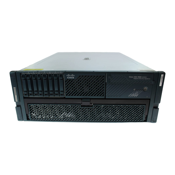
Figure 1-1 Front Panel Cisco IPS 4270 SERIES Intrusion Prevention Sensor Active LED System LED Power Status LED Management 0/0 LED Management 0/1 LED Power Cisco ASA 5580 Series Adaptive Security Appliance Hardware Installation Guide OL-12920-01... -
Page 16: Rear Panel
Pushing the button again will cause it to turn off again. Rear Panel Rear Panel Overview, page 1-5 • Ethernet Port Activity Indicators, page 1-6 • • Power Supply Indicators, page 1-7 Cisco ASA 5580 Series Adaptive Security Appliance Hardware Installation Guide OL-12920-01... -
Page 17: Rear Panel Overview
Reserved slot Example of a populated slot Reserved slot Console port 10 Management ports For more information about the network interfaces, see the “Network Interfaces” section on page 1-10. Cisco ASA 5580 Series Adaptive Security Appliance Hardware Installation Guide OL-12920-01... -
Page 18: Ethernet Port Activity Indicators
Green: link to network Fiber (one LED) Flashing green: linked with activity on the network Management port Green (right): link to network Flashing green (left): linked with activity on the network Cisco ASA 5580 Series Adaptive Security Appliance Hardware Installation Guide OL-12920-01... -
Page 19: Power Supply Indicators
No AC power to any power supply Flashing Power supply failure (over current) No AC power to this power supply Flashing • AC power present • Standby mode Normal Cisco ASA 5580 Series Adaptive Security Appliance Hardware Installation Guide OL-12920-01... -
Page 20: Internal Components
Internal Components Figure 1-4 shows the internal components of the ASA 5580. Figure 1-4 Internal Components 1, 3 4, 5, 7 Power supply Fans Interface expansion slots 6 Diagnostic panel Cisco ASA 5580 Series Adaptive Security Appliance Hardware Installation Guide OL-12920-01... -
Page 21: Diagnostic Panel
Processor memory module board I/O BD System board System NMI switch CPU BD (interlock error) System board PPM X Processor power module 1A-32D DIMM Slot PROC X Processor FAN X Cisco ASA 5580 Series Adaptive Security Appliance Hardware Installation Guide OL-12920-01... -
Page 22: Network Interfaces
High Capacity (PCI Express x8 non-hot-plug)—Slots 5, 7, and 8. • You can use the show io-bridge command to see the traffic throughput over each bus. For more information about using the command, see the Cisco ASA 5580 Adaptive Security Appliance Command Reference. Optimizing Performance You should use the high-capacity slots for 10-Gigabit Ethernet adapters;... -
Page 23: Pci Adapters
2-Port 10-Gigabit Ethernet Fiber PCI Adapter Provides two 10000Base-SX (fiber) interfaces. These interfaces require a multi-mode fiber cable with an LC connector to connect to the SX interface of the sensor. Cisco ASA 5580 Series Adaptive Security Appliance Hardware Installation Guide 1-11 OL-12920-01... -
Page 24: I/O Bridges
7 and 8 on the same bridge while slots 3 through 6 remain un- or under-populated. (See the “Expansion Slots and PCI Buses” section on page 1-10 for more information about bus types.) Cisco ASA 5580 Series Adaptive Security Appliance Hardware Installation Guide 1-12 OL-12920-01... -
Page 25: Interface Numbering
105 lb (47.6 kg) Form factor 4 RU, standard 19-inch rack-mountable Power Rated input voltage 100 to 127 VAC 200 to 240 VAC Rated input frequency 50 to 60 Hz Cisco ASA 5580 Series Adaptive Security Appliance Hardware Installation Guide 1-13 OL-12920-01... - Page 26 If it does not, configuration synchronization from the unit with the larger flash memory to the unit with the smaller flash memory will fail. Cisco ASA 5580 Series Adaptive Security Appliance Hardware Installation Guide 1-14 OL-12920-01...
-
Page 27: Chapter 2 Safety And Site Requirements
If you need to remove the chassis cover to install a hardware component, such as additional memory or an interface card, doing so does not affect your Cisco warranty. Upgrading the ASA does not require any special tools and does not create any radio frequency leaks. -
Page 28: Preventing Electrostatic Discharge Damage
• Install the ASA in compliance with local and national electrical codes as listed in the Regulatory Compliance and Safety Information for the Cisco ASA 5580 document. • The ASA model equipped with AC-input power supplies are shipped with a 3-wire electrical cord with a grounding-type plug that fits only a grounding-type power outlet. -
Page 29: Site Environment
The chassis does not have a user-selectable operating range. Refer to the label on the chassis for the correct AC-input power requirement. Several styles of AC-input power supply cords are available; make sure you have the correct – style for your site. Cisco ASA 5580 Series Adaptive Security Appliance Hardware Installation Guide OL-12920-01... -
Page 30: Configuring Equipment Racks
Baffles can help to isolate exhaust air from intake air, which also helps to draw cooling air through • the chassis. The best placement of the baffles depends on the airflow patterns in the rack. Experiment with different arrangements to position the baffles effectively. Cisco ASA 5580 Series Adaptive Security Appliance Hardware Installation Guide OL-12920-01... -
Page 31: Chapter 3 Installing The Asa 5580
DC circuit, locate the circuit breaker on the panel board that services the DC circuit, switch the circuit breaker to the OFF position, and tape the switch handle of the circuit breaker in the OFF position. Cisco ASA 5580 Series Adaptive Security Appliance Hardware Installation Guide OL-12920-01... - Page 32 Repeat Step 1 for each chassis side rail. Step 2 To remove the chassis side rail, lift the latch, and slide the rail forward, as shown in Figure 3-2. Step 3 Cisco ASA 5580 Series Adaptive Security Appliance Hardware Installation Guide OL-12920-01...
- Page 33 If you are installing the ASA 5580 in a shallow rack, one that is less than 28.5 in. (72.39 cm), remove Step 4 the screw from the inside of the slide assembly before continuing with Step 5, as shown in Figure 3-3. Cisco ASA 5580 Series Adaptive Security Appliance Hardware Installation Guide OL-12920-01...
- Page 34 Chapter 3 Installing the ASA 5580 Rack-Mounting the Chassis Figure 3-3 Screw Inside the Slide Assembly < 2 8 . 5 ” Cisco ASA 5580 Series Adaptive Security Appliance Hardware Installation Guide OL-12920-01...
- Page 35 Line up the studs on the slide assembly with the holes on the inside of the rack and snap into place. Adjust the slide assembly lengthwise to fit the rack. The spring latch locks the slide assembly into position. Figure 3-4 Slide Assembly Attachment Cisco ASA 5580 Series Adaptive Security Appliance Hardware Installation Guide OL-12920-01...
- Page 36 Line up the bracket on the slide assembly with the rack holes, install two screws (top and bottom) on each end of the slide assembly, as shown in Figure 3-6. Cisco ASA 5580 Series Adaptive Security Appliance Hardware Installation Guide OL-12920-01...
- Page 37 Rack-Mounting the Chassis Figure 3-6 Lining up the Bracket Repeat for each slide assembly. Extend the slide assemblies out of the rack, as shown in Figure 3-7. Step 6 Cisco ASA 5580 Series Adaptive Security Appliance Hardware Installation Guide OL-12920-01...
- Page 38 When installing a ASA 5580 in an empty rack, you must support the ASA 5580 from the front until the Warning blue slide tabs are activated and the ASA 5580 is pushed completely in to the rack, or the rack can tip. Cisco ASA 5580 Series Adaptive Security Appliance Hardware Installation Guide OL-12920-01...
-
Page 39: Connecting Interface Cables
To connect cables to the network interfaces, perform the following steps: Step 1 Place the chassis on a flat, stable surface, or in a rack (if you are rack-mounting it). Step 2 Connect to the Management port. Cisco ASA 5580 Series Adaptive Security Appliance Hardware Installation Guide OL-12920-01... - Page 40 Console port of the ASA 5580. Set up the terminal as follows: 9600 baud (default), 8 data bits, no parity, 1 stop bits, and Flow Control (FC) = Hardware. Cisco ASA 5580 Series Adaptive Security Appliance Hardware Installation Guide 3-10 OL-12920-01...
- Page 41 “Network Interfaces” section on page 1-10 for more information. Connect one end of an Ethernet cable to an Ethernet port in slots 3 through 8, as shown in Figure 3-11. Cisco ASA 5580 Series Adaptive Security Appliance Hardware Installation Guide 3-11 OL-12920-01...
- Page 42 Install the electrical cables at the back of the ASA. Attach the power cables and plug them in to a power Step 5 source (we recommend a UPS), as shown in Figure 3-12. Cisco ASA 5580 Series Adaptive Security Appliance Hardware Installation Guide 3-12 OL-12920-01...
-
Page 43: Installing The Fips Enclosure
The FIPS enclosures may cover the serial number on the chassis. You will need the serial number for calls made to Cisco Technical Support. Before you install the FIPS enclosures, copy the serial number on a label and stick it on the chassis where it can be retrieved or viewed easily. -
Page 44: Overview
Installing the FIPS Enclosure Overview Figure 13 shows the front shield assembly of the FIPS enclosure for the ASA 5580. Figure 13 Front Shield Assembly Self-adhesive tape with liner Cisco ASA 5580 Series Adaptive Security Appliance Hardware Installation Guide 3-14 OL-12920-01... -
Page 45: Installing The Fips Enclosure
Installing the Front Shield Assembly, page 3-15 • Installing the Rear Shield Assembly, page 3-18 The maximum operating temperature for the Cisco ASA 5580 with the shields installed should be 32C. Note Installing the Front Shield Assembly To install the front shield assembly, you must first pull out the processor module from the chassis. To pull out the processor module, perform the following steps: Power off the ASA. - Page 46 Front Surround Panel and the Front Panel Step 6 Clean the chassis of any grease, dirt or oil with alcohol where the self-adhesive tape will stick on the chassis. Cisco ASA 5580 Series Adaptive Security Appliance Hardware Installation Guide 3-16 OL-12920-01...
- Page 47 Push the module back into the chassis and use the handle to lock the module into place. See Figure 18 Step 10 Figure 18 Locking the Module into Place Cisco ASA 5580 SERIES Adaptive Security Appliance Cisco ASA 5580 Series Adaptive Security Appliance Hardware Installation Guide 3-17 OL-12920-01...
-
Page 48: Installing The Rear Shield Assembly
Secure the shield into place using the screws provided in the kit. See Figure Step 2 Figure 20 Install the Rear Shield on the Rear of the Chassis Cisco ASA 5580 Series Adaptive Security Appliance Hardware Installation Guide 3-18 OL-12920-01... -
Page 49: Applying Tamper Evident Labels
Adaptive Security Appliance Apply six tamper evident labels to the back of the chassis as shown in Figure Step 2 Figure 22 ASA 5580 Tamper Evident Label Placement Cisco ASA 5580 Series Adaptive Security Appliance Hardware Installation Guide 3-19 OL-12920-01... - Page 50 ASA 5580 Tamper Evident Label Placement Step 4 Apply one tamper evident label to the right of the chassis as shown in Figure Figure 24 ASA 5580 Tamper Evident Label Placement Cisco ASA 5580 Series Adaptive Security Appliance Hardware Installation Guide 3-20 OL-12920-01...
-
Page 51: Removing And Replacing The Chassis Cover
The BIOS on the ASA chassis is specific to the ASA and must only be upgraded under instructions from Caution Cisco with BIOS files obtained from the Cisco website. Installing a non-Cisco or third-party BIOS on the ASA voids the warranty. -
Page 52: Removing The Chassis Cover
Removing the Chassis Cover To remove the chassis cover, perform the following steps: Removing the chassis cover does not affect Cisco warranty. Upgrading the ASA does not require any Note special tools and does not create any radio frequency leaks. - Page 53 4-2. Step 4 Figure 4-2 Sliding the Chassis Cover Cis co AS A 55 80 SE RIE S Ad ap tiv e Se cu rit y Ap pli an Cisco ASA 5580 Series Adaptive Security Appliance Hardware Installation Guide OL-12920-01...
-
Page 54: Replacing The Chassis Cover
Removing and Installing the Interface Cards The ASA 5580 has nine expansion card slots. For detailed information about network interfaces and available cards, see the “Network Interfaces” section on page 1-10. Cisco ASA 5580 Series Adaptive Security Appliance Hardware Installation Guide OL-12920-01... -
Page 55: Removing The Interface Cards
Step 7 Figure 4-3 Unlocking the Expansion Card Slot and Installing the Card PS 2 PC I-E x4 PC I-E x8 PC I-E x4 PC I-E x8 PC I-E x4 Cisco ASA 5580 Series Adaptive Security Appliance Hardware Installation Guide OL-12920-01... -
Page 56: Installing An Interface Cards
Slide the server back in to the rack by pressing the server rail-release handles. Step 3 Step 4 Reconnect the power cables to the Cisco ASA 5580 series adaptive security appliance. Step 5 Power on the Cisco ASA 5580 series adaptive security appliance. - Page 57 P C I- E x P C I- X 1 0 0 M H z P S 1 C O N S O M G M T 0 M G M T 0 Cisco ASA 5580 Series Adaptive Security Appliance Hardware Installation Guide OL-12920-01...
- Page 58 P C I- X 1 0 0 M H z P S 1 C O N S O C O N S O M G M T 0 M G M T 0 Cisco ASA 5580 Series Adaptive Security Appliance Hardware Installation Guide OL-12920-01...
-
Page 59: Installing The Power Supply
P C I- E x P C I- X 1 0 0 M H z P S 1 C O N S O M G M T 0 M G M T 0 Cisco ASA 5580 Series Adaptive Security Appliance Hardware Installation Guide OL-12920-01... -
Page 60: Removing And Installing Fans
Power on the ASA. Step 5 Removing and Installing Fans There are six fans in the Cisco ASA 5580 series adaptive security appliance. For the fan locations, see Figure 1-4 on page 1-8. The Cisco ASA 5580 series adaptive security appliance supports redundant hot-pluggable fans in a 5 + 1 configuration to provide proper airflow. -
Page 61: Removing The Fan
Step 4 To remove the fan, grasp the red plastic handle and pull the handle up, see Figure 4-9. Remove and replace one fan at a time. Note Cisco ASA 5580 Series Adaptive Security Appliance Hardware Installation Guide 4-11 OL-12920-01... -
Page 62: Installing The Fan
If the front panel internal system health indicator is not green after you install a fan, reseat the Note fan. Replace the chassis cover. Step 4 Slide the ASA back in to the rack by pressing the rail-release handles. Step 5 Cisco ASA 5580 Series Adaptive Security Appliance Hardware Installation Guide 4-12 OL-12920-01... -
Page 63: Upgrading The Asa 5580-20 To An Asa 5580-40
Activation Key (PAK) when the order is fulfilled. Per the enclosed instructions, you should visit http://www.cisco.com/go/license, where you will be prompted to enter your contact information and PAK number along with the serial number of your module. The software on the Content Security Edition module will be enabled for the new user count and/or Plus functionality automatically and transparently the next time it checks for updates. - Page 64 Firmly holding the module, press the release buttons and pull the module out of the ASA, see Step 4 Figure 4-11. Figure 4-11 Release Button Location Release buttons Module Release the latch, and open the cover. Step 5 Cisco ASA 5580 Series Adaptive Security Appliance Hardware Installation Guide 4-14 OL-12920-01...
-
Page 65: Installing A Processor
To install a processor, perform the following steps: Attatch the grounding strap to a flat, unpainted surface on the inside of the chassis. Step 1 Open the heatsink retaining bracket, see Figure 4-12. Step 2 Cisco ASA 5580 Series Adaptive Security Appliance Hardware Installation Guide 4-15 OL-12920-01... - Page 66 The pins on the processor socket are very fragile. Any damage to them may require replacing the system Caution board. Step 3 Remove the processor socket protective cover, see Figure 4-13. Retain the cover for future use. Figure 4-13 Removing the Processor Socket Protective Cover Cisco ASA 5580 Series Adaptive Security Appliance Hardware Installation Guide 4-16 OL-12920-01...
- Page 67 Be sure the processor remains inside the processor installation tool. Step 5 If the processor has separated from the installation tool, carefully reinsert the processor in the tool, see Figure 4-15. Cisco ASA 5580 Series Adaptive Security Appliance Hardware Installation Guide 4-17 OL-12920-01...
- Page 68 The processor is designed to fit one way into the socket. Use the alignment guides on the processor and Caution socket to properly align the processor with the socket. Cisco ASA 5580 Series Adaptive Security Appliance Hardware Installation Guide 4-18 OL-12920-01...
- Page 69 Figure 4-17. Figure 4-17 The Processor Installation Tool Step 8 Close the processor retaining bracket and the processor retaining latch, see Figure 4-18. Cisco ASA 5580 Series Adaptive Security Appliance Hardware Installation Guide 4-19 OL-12920-01...
- Page 70 After the cover is removed, do not touch the thermal interface media. Step 10 Install the heatsink, you must press hard to clamp it down, see Figure 4-19. Figure 4-19 Installing the Heatsink Cisco ASA 5580 Series Adaptive Security Appliance Hardware Installation Guide 4-20 OL-12920-01...
- Page 71 Figure 4-21. Always install a processor power module when you install a processor. The system fails to boot Note if the corresponding processor power module is missing. Cisco ASA 5580 Series Adaptive Security Appliance Hardware Installation Guide 4-21 OL-12920-01...
- Page 72 Chapter 4 Maintenance and Upgrade Procedures Upgrading the ASA 5580-20 to an ASA 5580-40 Figure 4-21 Installing the Processor Power Module Cisco ASA 5580 Series Adaptive Security Appliance Hardware Installation Guide 4-22 OL-12920-01...
- Page 73 Install the memory module into the ASA. The four memory modules should be installed in slots 17I, 18I, Step 13 25M, and 26M, see Figure 4-22. Memory location before upgrading are 1A, 2A, 3B, 4B 9E, 10E, 11F, 12F. Note Figure 4-22 DIMM slot identification Cisco ASA 5580 Series Adaptive Security Appliance Hardware Installation Guide 4-23 OL-12920-01...
-
Page 74: Troubleshooting Loose Connections
Make sure all cables are properly aligned and securely connected for all external and internal • components. Remove and check all data and power cables for damage. Make sure no cables have bent pins or • damaged connectors. Cisco ASA 5580 Series Adaptive Security Appliance Hardware Installation Guide 4-24 OL-12920-01... - Page 75 Check any interlock or interconnect indicators that indicate a component is not connected properly. • If problems continue, remove and reinstall each device, checking the connectors and sockets for bent pins or other damage. Cisco ASA 5580 Series Adaptive Security Appliance Hardware Installation Guide 4-25 OL-12920-01...
- Page 76 Chapter 4 Maintenance and Upgrade Procedures Troubleshooting Loose Connections Cisco ASA 5580 Series Adaptive Security Appliance Hardware Installation Guide 4-26 OL-12920-01...
-
Page 77: Appendix
10BaseT and the 100BaseTX connector (RJ-45). Figure A-1 10/100 Port Pinouts Label 4 5 6 7 8 Figure A-2 shows the 10BaseT, 100BaseTX, and 1000BASE-T connector (RJ-45). Cisco ASA 5580 Series Adaptive Security Appliance Hardware Installation Guide OL-12920-01... - Page 78 Console Port (RJ-45) Cisco products use the following types of RJ-45 cables: • Straight-through • Crossover Cisco does not provide these cables; they are widely available from other sources. Note Figure A-3 shows the RJ-45 cable. Figure A-3 RJ-45 Cable...
-
Page 79: Console Rj-45 To Db-9 Adapter
Console RJ-45 to DB-9 Adapter Table A-2 lists the cable pinouts for RJ-45 to DB-9 or DB-25. Table A-2 Cable Pinouts for RJ-45 to DB-9 or DB-25 Signal RJ-45 Pin DB-9 Pin Cisco ASA 5580 Series Adaptive Security Appliance Hardware Installation Guide OL-12920-01... -
Page 80: Sfp Fiber Ports
SFP Port Cabling Specifications Cisco Product Wavelength Core Size Number (nanometer) (micron) Baud Rate Cable Distance GLC-SX-MM= 62.5 1.0625 300 m 50.0 1.0625 500 m GLC-LH-SM= 1300 1.0625 10 km Cisco ASA 5580 Series Adaptive Security Appliance Hardware Installation Guide OL-12920-01... -
Page 81: I N D E X
Ethernet interface cards Auto-MDI/MDIX 1-13 power supplies Ethernet port indicators specifications 1-13 ASA 5580 T-15 Torx screwdriver 4-7, 4-10 expansion card slots auto-MDI/MDIX 1-13 ASA 5580 Cisco ASA 5580 Adaptive Security Appliance Hardware Maintenance Guide IN-1 OL-12920-01... - Page 82 ASA 5580 1-13 installing removing internal health information Diagnostic Panel T-15 Torx screwdriver ASA 5580 4-7, 4-10 troubleshooting chassis loose connections 4-24 loose connections Diagnostic Panel (ASA 5580) chassis 4-24 Cisco ASA 5580 Adaptive Security Appliance Hardware Maintenance Guide IN-2 OL-12920-01...
- Page 83 Index ventilation fans warranty Cisco ASA 5580 Adaptive Security Appliance Hardware Maintenance Guide IN-3 OL-12920-01...
- Page 84 Index Cisco ASA 5580 Adaptive Security Appliance Hardware Maintenance Guide IN-4 OL-12920-01...