IBM 2498B24 - System Storage SAN24B-4 Switch Installation, Service And User Manual
User guide
Hide thumbs
Also See for 2498B24 - System Storage SAN24B-4 Switch:
- Installation, service and user manual (83 pages)
Table of Contents
Advertisement
IBM System Storage SAN24B-4 Express
Installation, Service, and User Guide
Service information: 2498 - B24, 24E
Read Before Using
This product contains software that is licensed under written license agreements. Your use of such software is subject to
the license agreements under which they are provided.
GA32-0580-02
Advertisement
Table of Contents

Related Manuals for IBM 2498B24 - System Storage SAN24B-4 Switch


Summary of Contents for IBM 2498B24 - System Storage SAN24B-4 Switch
- Page 1 IBM System Storage SAN24B-4 Express Installation, Service, and User Guide Service information: 2498 - B24, 24E Read Before Using This product contains software that is licensed under written license agreements. Your use of such software is subject to the license agreements under which they are provided.
- Page 3 IBM System Storage SAN24B-4 Express Installation, Service, and User Guide Service information: 2498 - B24, 24E GA32-0580-02...
- Page 4 © Copyright IBM Corporation 2008, 2010. US Government Users Restricted Rights – Use, duplication or disclosure restricted by GSA ADP Schedule Contract...
-
Page 5: Third Edition
Read this first Summary of changes This is the third edition of the IBM System Storage SAN24B-4 Express Installation, Service, and User Guide. The content changes since the last edition of this publication are noted by a vertical line placed in the left margin beside each change. -
Page 6: Taiwan Contact Information
GUI. Vendor software This product includes certain vendor software that is not covered under the IBM license agreement. IBM makes no representation about the accessibility features of these products. Contact the vendor for the accessibility information about its products. - Page 7 Department GZW 9000 South Rita Road Tucson, Arizona 85744-0001 U.S.A. When you send information to IBM, you grant IBM a nonexclusive right to use or distribute the information in any way it believes appropriate without incurring any obligation to you.
- Page 8 SAN24B-4 Express Installation, Service, and User Guide...
-
Page 9: Table Of Contents
. xiii Weight and physical dimensions . . 33 Brocade documents . xiii Environmental requirements . . 33 IBM and Brocade product matrix . . xiv Facility requirements . . 34 Safety and environmental notices . . xiv System specifications . - Page 10 viii SAN24B-4 Express Installation, Service, and User Guide...
-
Page 11: Figures
Detailed view, location of LEDs on the switch Mounting the moving portion of the slide and SFP installation and bail closing. . 27 mounting brackets to the switch . 13 Removing an SFP . 28 © Copyright IBM Corp. 2008, 2010... - Page 12 SAN24B-4 Express Installation, Service, and User Guide...
-
Page 13: Tables
Tables Brocade and IBM product and model number Ethernet LED patterns . . 25 matrix . . xiv Management options for the switch . 30 Sample caution notices . . xviii Physical dimensions and weight of the switch Parts supplied with the rack-mount kit Environmental requirements . - Page 14 SAN24B-4 Express Installation, Service, and User Guide...
-
Page 15: About This Document
Fibre Channel, and storage area network (SAN) ™ technologies. It describes how to install, service, and use the IBM System Storage SAN24B-4 Express (machine type 2498, models 24B and E24). Throughout this document, the product is referred to as the SAN24B-4, or simply the switch to apply to both models. -
Page 16: Ibm And Brocade Product Matrix
When you use any of the Brocade documents, you will notice that the model numbers reflect the original Brocade products. Table 1 provides a product matrix for you to use to correlate the Brocade products and models to the IBM product names and machine types and model numbers. Products withdrawn from marketing are not listed. -
Page 17: Danger Notices
The following notices and statements are used in IBM documents. They are listed below in order of increasing severity of potential hazards. Follow the links for more detailed descriptions and examples of the danger, caution, and attention notices in the sections that follow. - Page 18 DANGER An electrical outlet that is not correctly wired could place hazardous voltage on metal parts of the system or the devices that attach to the system. It is the responsibility of the customer to ensure that the outlet is correctly wired and grounded to prevent an electrical shock.
-
Page 19: Caution Notices
Electrical voltage and current from power, telephone, and communication cables are hazardous. To avoid a shock hazard: v Connect power to this unit only with the IBM provided power cord. Do not use the IBM provided power cord for any other product. -
Page 20: Sample Caution Notices
Table 2. Sample caution notices If the symbol is... It means..A hazardous electrical condition with less severity than electrical danger. A generally hazardous condition not represented by other safety symbols. A specification of product weight that requires safe lifting practices. The weight range of the product is listed below the graphic, and the graphic and the wording of the caution varies, depending on the weight... - Page 21 Safety labels As an added precaution, safety labels are often installed directly on products or product components to warn of potential hazards. These can be either danger or caution notices, depending upon the level of the hazard. The actual product safety labels may differ from these sample safety labels: DANGER Hazardous voltage, current, or energy levels are present inside any component that has this label attached.
-
Page 22: Rack Safety
Rack safety Rack installation DANGER Observe the following precautions when working on or around your IT rack system: v Heavy equipment—personal injury or equipment damage might result if mishandled. v Always lower the leveling pads on the rack cabinet. v Always install stabilizer brackets on the rack cabinet. v To avoid hazardous conditions due to uneven mechanical loading, always install the heaviest devices in the bottom of the rack cabinet. - Page 23 Rack relocation (19" rack) CAUTION: Removing components from the upper positions in the rack cabinet improves rack stability during relocation. Follow these general guidelines whenever you relocate a populated rack cabinet within a room or building: v Reduce the weight of the rack cabinet by removing equipment starting at the top of the rack cabinet.
-
Page 24: Product Recycling And Disposal
Product recycling and disposal Refer to the IBM Systems Environmental Notices and User Guide (Z125-5823) for translated environmental statements and information regarding product recycling and disposal. This document may be provided either in printed version or on the product documentation CD. -
Page 25: Chapter 1. Introducing The San24B-4 Express Switch
The IBM System Storage SAN24B-4 Express is a cost-effective and highly-scalable 1, 2, 4, or 8 Gbit/sec switch, designed for small to mid-sized businesses. It runs on the Fabric Operating System (Fabric OS) and is compatible with other IBM switches, which enables seamless connectivity into heterogeneous SAN environments. -
Page 26: Supported Connectivity
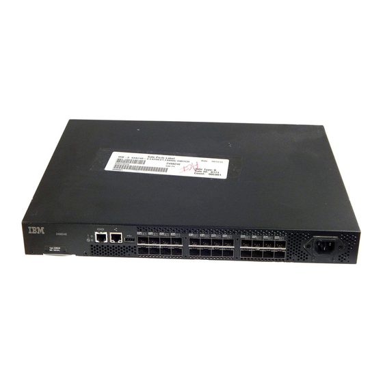
SAN connectivity products, and configuration options can be found in the interoperability matrices at the following web site: www.ibm.com/servers/storage/support/san. Port side of the switch Figure 1 shows the port side of the switch. All LEDs are on the port side of the switch: the nonport side is used to allow the free flow of air. -
Page 27: Nonport Side Of The Switch
The additional ports are ready to be unlocked in the switch firmware. The license might be part of the licensed paper pack supplied with switch software, or you can purchase the license separately from IBM, who will provide you with a key to unlock it. -
Page 28: Supported Optional Features
Figure 2. Trunking groups v A–Trunk Group 1: ports 0 through 7 v B–Trunk Group 2: ports 8 through 15 v C–Trunk Group 3: ports 16 through 23 Note: ISL Trunking is optional software that allows you to create trunking groups of ISLs between adjacent switches. - Page 29 For more information on the use of these features, refer to the Fabric OS Administrator’s Guide. Chapter 1. Introducing the SAN24B-4 Express switch...
- Page 30 SAN24B-4 Express Installation, Service, and User Guide...
-
Page 31: Chapter 2. Installing And Configuring The Switch
SAN24B-4 to operate as a switch. The installation instructions in this document apply to both Switch and Access Gateway modes. To configure and operate the SAN24B-4 in Access Gateway mode, refer to the IBM System Storage SAN24B-4 Access Gateway Quick Start Guide and the Access Gateway Administrator's Guide. -
Page 32: Installation And Safety Considerations
– EZSwitchSetup CD – One LC wrap plug Installation and safety considerations Use this section to prepare your site for a safe and successful installation. Attention: Although the switch has been designed for customer installation and replacement procedures, you must first ensure that the rack into which the switch is to be installed is also customer accessible. -
Page 33: Installing A Stand-Alone Switch
v Plan a cabinet space that is 1 rack unit 4.45 cm (1.75 in.) high, 48.3 cm (19 in) wide. v Ground all equipment in the cabinet through a reliable branch circuit connection and maintain ground at all times. Do not rely on a secondary connection to a branch circuit, such as a power strip. -
Page 34: Time Required
v To allow the non-port side of the switch to slide out the cool-air side of the cabinet. In this installation, the port side of the switch is set 7.62 cm (3 in.) back from the edge of the cabinet, allowing a more gradual bend in the fiber optic cables. -
Page 35: Rack Assembly
Outer Slide EIA Rack Rail Inner Slide Detail A Front of Switch Detail A SJ000153 Figure 3. Rack assembly 1. Unpack the rack-mount kit and verify that all ordered items and parts are present and undamaged. See Table 3 for a list of parts and the quantities supplied. -
Page 36: Separating The Inner And Outer Rails
2. Separate the inner and outer slides. a. Open one of the slides until the lock engages. b. Press the lock release lever ( 1 in Figure 4) and remove the inner rail from the outer rail. SJ000046 Figure 4. Separating the inner and outer rails c. -
Page 37: Mounting The Moving Portion Of The Slide And Mounting Brackets To The Switch
Front SJ000047 Figure 5. Mounting the moving portion of the slide and mounting brackets to the switch c. Repeat step 3a on page 12 and step 3b on page 12 for the second inner rail on the other side of the switch chassis. 4. -
Page 38: Mounting The Fixed Portion Of The Rail And The
SJ000048 Figure 6. Mounting the fixed portion of the rail and the locking brackets to the rack 6. Install the outer (larger) slides in the rack, as shown in Figure 6. a. At the desired height, install the five M5 nut clips 5 . Put three M5 nut clips in the front of the rack and two in the back. -
Page 39: Recommendations For Cable Management
SJ000049 Figure 7. Inserting slides into the rack rails b. Check the alignment of the slides by sliding the switch in and out of the rack. Any difficulty moving the switch indicates lateral stress or misalignment. If this situation occurs, adjust the slide positions until the movement is smooth. -
Page 40: Configuring The Switch
Cables can be organized and managed in a variety of ways: for example, using cable channels on the sides of the cabinet or patch panels to minimize cable management. Following is a list of recommendations: v Plan for rack space required for cable management before installing the switch. v Leave at least 1 meter (3.28 ft) of slack for each port cable. -
Page 41: Creating A Serial Connection
2. After POST is complete, verify that the switch power and status LEDs on the left of the port side of the switch are green. Creating a serial connection You will perform all basic configuration tasks in this guide using a serial connection. -
Page 42: Setting The Date And Time
switch:admin> ipaddrset -ipv6 --add 1080::8:800:200C:417A/64 IP address is being changed...Done. 3. Complete the rest of the network information as prompted. Ethernet Subnetmask: [255.255.255.0] Ethernet IP Address: [192.168.74.102] Ethernet Subnetmask: [255.255.255.0] 4. Enter off to Disable DHCP when prompted. DHCP [OFF]: off Setting the date and time The switch maintains the current date and time inside a battery-backed real-time clock (RTC) circuit. - Page 43 The time zone setting has the following characteristics: v You can view the time zone settings. However, only those with administrative permissions can set the time zones. v The tsTimeZone setting automatically adjusts for Daylight Savings Time. v Changing the time zone on a switch updates the local time zone setup and is reflected in local time calculations.
- Page 44 All switches in the fabric maintain the current clock server value in non-volatile memory. By default, this value is the local clock server <LOCL> of the principal or primary FCS switch. Changes to the clock server value on the principal or primary FCS switch are propagated to all switches in the fabric.
-
Page 45: Chapter 3. Operating The Switch
System power LED–One LED (green) to indicate system power v System status LED–One LED (green/amber) to indicate system status v Ethernet status LEDs–Two LEDs to indicate speed and link status v Port status LEDs–24 LEDs (green/amber) to indicate status for each port © Copyright IBM Corp. 2008, 2010... -
Page 46: Led Locations
LED locations All the switch LEDs are located on the port side. Figure 8 shows the location of individual LEDs Figure 8. Detailed view, location of LEDs on the switch Item LED names and descriptions System power LED (green) System status LED (green/amber) Ethernet link status LED Ethernet link speed LED Port status LED for port 3... -
Page 47: Led Patterns
LED patterns Table 4 through Table 7 on page 25 summarize the switch LED locations, color, and meaning, as well as any recommended user response. Power status LED patterns The power status LED patterns are shown in Table 4 Table 4. Power status LED patterns, status, and recommended actions Recommended LED name LED color... -
Page 48: Port Led Patterns During Normal Operation
Table 6. Port LED patterns during normal operation Recommended LED name LED color Status of hardware action Port status No light No light or signal Check SFP and cable. carrier (SFP or cable) detected. Steady green Port is online No action is required. (connected to external device) but has no traffic. -
Page 49: Post And Boot Specifications
Ethernet LED patterns Each Ethernet port has two LEDs, which are described in Table 7 Table 7. Ethernet LED patterns Recommended LED name LED color Status of hardware action Ethernet speed LED No light Port speed is 10 No action is required. (right) Mb/sec. -
Page 50: Interpreting Post Results
Enter. If the switch prompt still does not display, try opening another telnet session or accessing through another management tool. If this is not successful, the switch did not successfully complete POST; contact IBM Service for repair. 3. Review the switch system log for errors. Any errors detected during POST are written to the system log, which is accessible through the errShow command. -
Page 51: Sfp Installation And Bail Closing
Figure 9. SFP installation and bail closing Item Description Switch chassis SFP with open bale Closed bale Chapter 3. Operating the switch... -
Page 52: Removing An Sfp
Non-bailed SFPs can be damaged by the removal process and are not recommended. Refer to the interoperability matrix at the following web site: www.ibm.com/servers/storage/support/san for a list of supported SFPs and devices. 5. Repeat this procedure for the remaining ports, as required. - Page 53 Item Description Bail Cabled Fibre Channel ports Testing a port, SFP, and fiber cable The PortLoopbackTest command is used to verify the functional operation of the switch by sending frames from the port "N" transmitter and looping them back into the same port "N" receiver. The loopback is done at the parallel loopback path. The path exercised in this test does not include the media or the fiber cable.
-
Page 54: Diagnostic Tests
11. Simulate the data transmission scenario when the error occurred. If the error does not reappear, the original SFP was defective, and should be discarded. If the error does reappear, the cable is defective. Replace the cable and discard the original cable. 12. - Page 55 Table 8. Management options for the switch (continued) Management tool Out-of-band In-band support support EFCM (optional purchase) Ethernet or serial IP over Fibre For information, refer to the EFC Manager Software User Manual. connection Channel Note: To achieve in-band support for IP over Fibre Channel, the software must be run on both the HBA and the switch, and it must be supported by both the HBA and HBA driver.
- Page 56 SAN24B-4 Express Installation, Service, and User Guide...
-
Page 57: Appendix. Product Specifications
Note: The -10° to 40° Celsius range applies to the ambient air temperature at the air intake vents on the nonport side of the switch. The temperature inside the switch can be up to 80° Celsius during switch operation. If the internal © Copyright IBM Corp. 2008, 2010... -
Page 58: Facility Requirements
temperature range exceeds the operating ranges of the components, the LEDs, error messages, and Fabric Watch alerts indicate a problem. Enter the tempShow or Fabric Watch commands to view temperature status. Facility requirements To ensure correct operation of the switch, the facility where the switch is in use must meet the requirements listed in Table 11. -
Page 59: System Specifications
Descriptions Autoconfiguring port types F_Port, FL_Port, M_Port, N_Port, and E_Port System architecture Nonblocking shared-memory switch System processor IBM PowerPC 440EPx, 667 MHz SDRAM 512 MB DDR2 SDRAM onboard memory operating at 133 MHz Compact flash 1 GB ANSI Fibre Channel protocol... -
Page 60: Data Transmission Ranges
Data transmission ranges Table 14 provides the data transmission ranges for different cable types and port speeds. Table 14. Data transmission ranges Port speed Cable size (microns) Short wavelength (SWL) Long wavelength (LWL) 1 Gbps 500 m (1,640 ft) 62.5 300 m (984 ft) up to 10 km (6.2 mi) 2 GGbps... -
Page 61: Supported Sfps And Hbas
SFPs for the base configuration. Use only SFPs that are tested and supported. For the most up to date list of supported SFPs and HBAs for the switch, refer to the product interoperability matrix at the IBM SAN Support web pages at: www.ibm.com/servers/storage/support/san... - Page 62 SAN24B-4 Express Installation, Service, and User Guide...
-
Page 63: Notices
The materials at those web sites are not part of the materials for this IBM product and use of those web sites is at your own risk. - Page 64 Information concerning non-IBM products was obtained from the suppliers of those products, their published announcements or other publicly available sources. IBM has not tested those products and cannot confirm the accuracy of performance, compatibility or any other claims related to non-IBM products.
-
Page 65: Trademarks
International Business Machines Corporation in the United States, other countries, or both. A complete and current list of other IBM trademarks is available on the Web at http://www.ibm.com/legal/copytrade.shtml Adobe, the Adobe logo, PostScript, and the PostScript logo are either registered trademarks or trademarks of Adobe Systems Incorporated in the United States, and/or other countries. -
Page 66: Electronic Emission Notices
Properly shielded and grounded cables and connectors must be used in order to meet FCC emission limits. IBM is not responsible for any radio or television interference caused by using other than recommended cables and connectors or by unauthorized changes or modifications to this equipment. -
Page 67: Germany Electromagnetic Compatibility Directive
Klasse A ein. Um dieses sicherzustellen, sind die Geräte wie in den Handbüchern beschrieben zu installieren und zu betreiben. Des Weiteren dürfen auch nur von der IBM empfohlene Kabel angeschlossen werden. IBM übernimmt keine Verantwortung für die Einhaltung der Schutzanforderungen, wenn das Produkt ohne Zustimmung der IBM verändert bzw. -
Page 68: People's Republic Of China Class A Electronic Emission Statement
Generelle Informationen: Das Gerät erfüllt die Schutzanforderungen nach EN 55024 und EN 55022 Klasse People's Republic of China Class A Electronic Emission Statement Japan VCCI Council Class A Statement Translation: This is a Class A product based on the standard of the VCCI Council. If this equipment is used in a domestic environment, radio interference may occur, in which case, the user may be required to take corrective actions. -
Page 69: Japan Electronics And Information Technology Industries Association (Jeita) Statement
Japan Electronics and Information Technology Industries Association (JEITA) Statement Japanese Electronics and Information Technology Industries Association (JEITA) Confirmed Harmonics Guideline (products less than or equal to 20 A per phase). Korea Communications Commission (KCC) Statement Please note that this equipment has obtained EMC registration for commercial use. In the event that it has been mistakenly sold or purchased, please exchange it for equipment certified for home use. - Page 70 SAN24B-4 Express Installation, Service, and User Guide...
-
Page 71: Index
Ethernet port 1 rack 8 creating a serial connection 17 EZSwitchSetup wizard 1 trunking groups 3 Inter-Switch-Link trunking 1 items included 7 LEDs 1 NPIV access gateway 1 optional 4 RJ45 Ethernet management port 1 © Copyright IBM Corp. 2008, 2010... - Page 72 SFPs 26 caution xvii SNMP danger xv management 30 environmental xiv, xxii specifications general 39 boot 25 IBM 39 rack data transmission ranges 36 patents 39 considerations 8 Fibre Channel ports 36 safety xiv requirements 8 general 35 SAN24B-4 Express Installation, Service, and User Guide...
- Page 73 specifications (continued) time memory 35 setting 18 physical dimensions 33 time zones POST 25 setting 18 power supply 36 trademarks 41 product 33 trunking groups serial port 36 ISL 3 system 35 weight 33 stand-alone switch 9 vendor software iv installing 9 vibration static IP address...
- Page 74 SAN24B-4 Express Installation, Service, and User Guide...
- Page 76 Part Number: 45W8145 Printed in USA GA32-0580-02...