Dell PowerConnect 2708 User Manual
Powerconnect 27xx systems, web-managed gigabit ethernet switches
Hide thumbs
Also See for PowerConnect 2708:
- Appendix (14 pages) ,
- Datasheet (12 pages) ,
- Getting started manual (51 pages)

Related Manuals for Dell PowerConnect 2708


Summary of Contents for Dell PowerConnect 2708
- Page 1 Dell™ PowerConnect™ 27XX Systems User’s Guide w w w . d e l l . c o m | s u p p o r t . d e l l . c o m...
- Page 2 Reproduction in any manner whatsoever without the written permission of Dell Inc. is strictly forbidden. Trademarks used in this text: Dell, Dell OpenManage, the DELL logo, and PowerConnect are trademarks of Dell Inc. Microsoft is a registered trademark of Microsoft Corporation.
-
Page 3: Table Of Contents
Switch Port Configurations ......PowerConnect 2708/2716/2724/2748 Front Panel Port Description ..Physical Dimensions . - Page 4 Connecting the Device to the Network ....Starting and Configuring the Dell™ PowerConnect™ 27XX Viewing Switch Operation ......
- Page 5 Resetting the Device ......Displaying Configuration on Demand ....Configuring System Information Defining Switch Information .
- Page 6 Contents...
-
Page 7: Introduction
PowerConnect management features are designed to minimize administrative management effort, while enhancing and improving network traffic control. System Description This section describes the hardware configurations of the PowerConnect 2708, PowerConnect 2716, PowerConnect 2724, and PowerConnect 2748. The switches are managed by Dell’s OpenManage Switch Administrator. -
Page 8: 16 1-Gigabit Ethernet Ports
16 1-Gigabit Ethernet Ports The following figure illustrates the PowerConnect 2716 front panel. Figure 1-2. PowerConnect 2716 Front Panel The PowerConnect 2716 switch supports 16 GbE copper ports. 24 1-Gigabit Ethernet Ports + 2 SFP Combo ports The following figure illustrates the PowerConnect 2724 front panel. Figure 1-3. -
Page 9: Features
Features General Features Head of Line Blocking Prevention Head of Line (HOL) blocking results in traffic delays and frame loss caused by traffic competing for the same egress port resources. HOL blocking queues packets, and the packets at the head of the queue are forwarded before packets at the end of the queue. - Page 10 Auto Negotiation Auto negotiation allows an Ethernet switch to advertise modes of operation. The auto negotiation function provides the means to exchange information between two Ethernet switches that share a point-to-point link segment, and to automatically configure both Ethernet switches to take maximum advantage of their transmission capabilities.
-
Page 11: Mac Address Supported Features
MAC Address Supported Features MAC Address Capacity Support The PowerConnect 2708, 2716, and 2724 switches support a total of 8K MAC addresses, and the PowerConnect 2748 supports a total of 16K MAC addresses. Auto-Learning MAC Addresses The switch enables MAC address auto-learning from incoming packets. The MAC addresses are stored in the Bridging Table. -
Page 12: Vlan Supported Features
Port-based VLANs classify incoming packets to VLANs based on their ingress port. Link Aggregation The PowerConnect 2708/2716/2724/2748 switches support up to six aggregated links. Each of the six aggregated links may be defined with up to four member ports to form a single Link Aggregated Group (LAG). -
Page 13: Ethernet Switch Management Features
Web browser. The system contains an Embedded Web Server (EWS), which serves HTML pages, through which the system can be monitored and configured. TFTP Trivial File Transfer Protocol The PowerConnect 2708/2716/2724/2748 switches support software boot image and software download through TFTP. Remote Monitoring Remote Monitoring (RMON) is an extension to the Simple Network Management Protocol (SNMP), which provides network traffic statistics. -
Page 15: Hardware Description
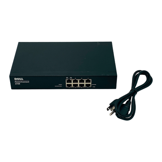
Switch Port Configurations PowerConnect 2708/2716/2724/2748 Front Panel Port Description The Dell™ PowerConnect™ 2708, 2716, 2724 and 2748 switches use 10/100/1000BASE-T ports on the front panel for connecting to a network. The Gigabit Ethernet ports can operate at 10, 100 or 1000 Mbps. These ports support auto- negotiation, duplex mode (Half or Full duplex), and flow control. - Page 16 Figure 2-2. PowerConnect 2708 Back Panel Figure 2-3. PowerConnect 2716 Front Panel On the front panel, there are 16 ports, which are numbered 1 to 16, top down and left to right. On each port there are LEDs to indicate the port status.
- Page 17 Figure 2-5. PowerConnect 2724 Front Panel On the front panel there are 24 ports which are numbered 1 to 24, top down and left to right. On each port there are LEDs to indicate the port status. There are two SFP (Small Form-Factor Plugable) ports, designated as ports 23 and 24, for fiber connection.
- Page 18 Figure 2-7. PowerConnect 2748 Front Panel On the front panel, there are 48 ports, which are numbered 1 to 48, top down and left to right. On each port, there are LEDs to indicate the port status. There are four SFP (Small Form- Factor Plugable) ports, designated as ports 45, 46, 47 and 48, for fiber connection.
-
Page 19: Physical Dimensions
The front panel contains LEDs that indicate the status of links, power supply, fan status, and Managed Mode status. Power LED On the PowerConnect 2708/2716/2724/2748 front panel there is a Power LED. The following table describes the Power Supply status LED indications. Table 2-1. Power LED Indications... -
Page 20: Fan Led (2748 Only)
Table 2-2. Managed Mode LED Indications LED Color Description Green Flashing Indicates diagnostics in progress, firmware loading, or Managed Mode transition. Green Solid Indicates the switch is in Managed Mode. Amber Solid Diagnostics has failed. Amber Flashing No valid image. Indicates Unmanaged mode or Secure mode (2748 only). -
Page 21: Managed Mode Button
No link is established. Managed Mode Button The PowerConnect 2708/2716/2724/2748 has a Managed Mode push button on the front panel. The Managed Mode button is for changing between Managed Mode and Unmanaged (or Secure) Mode. After a change from Unmanaged (or Secure) Mode to Managed Mode, the switch restores the configuration values to factory default settings. -
Page 22: Switch Ventilation Fan
Switch Ventilation Fan The PowerConnect 2748 switch has three fans and the PowerConnect 2724 switch has one fan for system ventilation. The PowerConnect 2708 and PowerConnect 2716 devices have no internal fans. Cables, Port Connections, and Pinout Information This section explains the switch physical interfaces, and provides information about cables and port connections. -
Page 23: Sfp Ports
Table 2-7. RJ-45 Pin Number Allocation for 10/100/ 1000BASE-T Ethernet Port Pin No Function TxRx 1+ TxRx 1- TxRx 2+ TxRx 2- TxRx 3+ TxRx 3- TxRx 4+ TxRx 4- SFP Ports The PowerConnect 2724 switch supports two SFP transceivers combo ports, and the PowerConnect 2748 switch supports four SFP transceivers combo ports for various fiber-based modules (1000BASE-SX or 1000BASE-LX). -
Page 24: Pin Connections For Sfp Interfaces
Transmitter non-inverted data in Transmitter inverted data in Transmitter ground (common with receiver ground) Power Connectors The PowerConnect 2708/2716/2724/2748 switches are powered by using the AC internal power supply. Internal Power Supply Connector The PowerConnect 2708, PowerConnect 2716, PowerConnect 2724 and PowerConnect 2748 switch systems supports a single internal power supply to provide power for switching operations. -
Page 25: Installing The Dell™ Powerconnect™ 27Xx
Installing the Dell™ PowerConnect™ 27XX This chapter contains information about unpacking, installation procedures, and how to make cable and port connections for the PowerConnect 2708, 2716, 2724, and 2748 devices. Installation Precautions CAUTION: Before performing any of the following procedures, read and follow the safety instructions... -
Page 26: Site Requirements
Mode. Site Requirements The PowerConnect 2708/2716/2724/2748 devices can be mounted in a standard equipment rack, placed on a tabletop, or mounted on the wall. Before installing the unit, verify that the site selected for the device meets the following site requirements: •... -
Page 27: Handling Static Sensitive Devices
Open the box or remove the box top. Carefully remove the device from the package and place it on a secure, stable and clean surface. Remove all packing material. Inspect the device and accessories for damage. Report any damage immediately to Dell. -
Page 28: Mounting The Device
Mounting the Device The following mounting instructions apply to the PowerConnect 2708/2716/2724/2748 devices. There are three device mounting options: • Installing in a Rack • Installing on a Flat Surface • Installing on a Wall Installation Precautions CAUTION Before performing any of the following procedures, read and follow the safety instructions... -
Page 29: Installing The Device
Installing the Device The following mounting instructions apply to all three hardware configurations of PowerConnect 2708, 2716, 2724 and 2748 devices. The section describes how to install a single device as a stand- alone device. Installing the Device in a Rack CAUTION: Disconnect all cables from the unit before mounting the device in a rack or cabinet. -
Page 30: Installing The Device On A Flat Surface
Installing the Device on a Flat Surface The device can be installed on a flat surface, such as a desk-top, if it is not installed on a rack or on a wall. The surface must be able to support the weight of the device and the device cables. Attach the self-adhesive rubber pads (provided with the device) on each marked location on the bottom of the chassis. -
Page 31: Connecting The Device To Ac Power Supply
Secure the unit to the wall with screws (not provided). Ensure that the ventilation holes are not obstructed. Figure 3-4. Mounting Device on a Wall Connecting the Device to AC Power Supply Using a 5-foot (1.5 m) standard power cable with safety ground connected, connect the power cable to the AC connector located on the back panel. -
Page 32: Connecting The Device To The Network
Figure 3-5. Back Panel Power Connector After connecting the device to a power source, confirm that the device is connected and operating correctly by examining the LEDs on the front panel. Connecting the Device to the Network To connect to an uplink port, use Category 5 Unshielded Twisted-Pair (UTP) cables with RJ-45 connectors at both ends. -
Page 33: Starting And Configuring The Dell™ Powerconnect™ 27Xx
Managed Mode. When a critical problem is detected, the POST process fails and the Managed Mode LED indicator turns solid amber (PowerConnect 2748). If the process fails in the PowerConnect 2708/2716/2724 switch the Managed Mode LED indicator turns solid red. Initial Configuration The switch is delivered from the factory in Unmanaged Mode. - Page 34 The following information must be obtained from the network administrator before configuring the device: • The IP address to be assigned to the VLAN 1 interface through which the device is to be managed (by default, every port is a member of the VLAN 1 in Managed Mode). •...
- Page 35 Enter the IP address, Subnet Mask and Default Gateway as supplied by the System Administrator. Click Apply Changes. The switch is configured with the updated configuration parameters.
-
Page 37: Using The Dell Openmanage™ Switch Administrator
Using the Dell OpenManage™ Switch Administrator This section provides an introduction to the Embedded Web Server (EWS), which serves HTML pages through which the user can monitor the switch interface. Understanding the Interface The home page contains a Tree View — located on the left side of the home page. The tree view provides an expandable view of the features and their components. - Page 38 Depending on the option selected, the area at the bottom of the Ethernet switch view displays other Ethernet switch information or dialog boxes for configuring parameters. The information buttons provide access to information about the Ethernet switch and access to Dell Support.
-
Page 39: Using The Openmanage Switch Administrator Buttons
Using the OpenManage Switch Administrator Buttons This section describes the buttons found on the Dell™ PowerConnect™ OpenManage Switch Administrator interface. Information Buttons Information buttons provide access to on-line support and online help, as well as information about the OpenManage Switch Administrator interfaces. -
Page 40: Starting The Application
Managed Mode button recovers the factory default setting (no password). For information about recovering a lost password, see "Managed Mode Button". NOTE: Passwords are both case-sensitive and alphanumeric. Click OK. The Dell PowerConnect OpenManage Switch Administrator home page opens. -
Page 41: Resetting The Device
Resetting the Device The Reset page resets the device. To open the Reset page, click Reset in the tree view. Figure 5-2. Reset Click Reset. A confirmation message displays. Click OK. The device is reset. -
Page 42: Displaying Configuration On Demand
Displaying Configuration on Demand The EWS shortens user wait time by providing Data Display on Demand. When the system retrieves vast amounts of configuration data, the data is divided into groups. The system administrator can peruse the configuration information by either selecting a specific interface or using the Previous and Next links. -
Page 43: Configuring System Information
Configuring System Information This section provides information for defining system parameters including switch status features, downloading switch software, and modifying switch parameters. Defining Switch Information Viewing the Switch Status The Switch Status page contains parameters for configuring and viewing general switch information, including the Product Name, Firmware Version, the system MAC Address, Asset Tag, Service Tag, System Name, Location Name, Serial Number, and System Up Time. -
Page 44: Viewing System Ip Address
Asset Tag (0-16 Characters) — Specifies the user-defined switch reference. Service Tag — The service reference number used when servicing the switch. System Name (0-32 Characters) — Defines the user-defined switch name. Location Name (0-32 Characters) — The location where the system is currently running. Serial Number —... - Page 45 Figure 6-2. IP Addressing DHCP — The DHCP client can be enabled to acquire the network configuration dynamically. The DHCP default value is Disable. This field enables the DHCP client. IP Address — Specifies the static IP Address currently assigned to the device. Subnet Mask—...
- Page 46 Configuring DHCP Client Open the IP Addressing page. Change the DHCP to Enable. Click Apply Changes. The switch requests from the DHCP server to assign a new dynamic IP Address, Subnet Mask, and Default Gateway Address to manage the device. The dynamic DHCP IP Address, DHCP Subnet Mask, and DHCP Default Gateway Address are displayed.
-
Page 47: Defining Interface Configuration
Defining Interface Configuration The Interface Configuration page enables the user to set the port parameters, such as port speed, port type, and additional port operational attributes. To open the page, click Interface Configuration in the tree view. Figure 6-3. Interface Configuration Interface —... - Page 48 Current Port Speed — The actual synchronized port speed, in bits per second. Admin Duplex — Full Duplex (FDX) indicates that the switch interface supports transmission between the device and another station, in both directions simultaneously. Half Duplex (HDX) indicates that the interface supports transmission between the device and the other station in one direction only at a time.
-
Page 49: Viewing Jumbo Frames
Auto — Use to automatically detect the cable type. Current MDI/MDIX — Displays the current MDI/MDIX status of the port. LAG — Specifies if port is a part of a LAG (Link Aggregated Group). Configuring the Interface Open the Interface Configuration page. Define the fields. -
Page 50: Creating Vlan Membership
Current — Shows what the current status is for Jumbo Frames support. After Reset — Indicates the Jumbo Frames status after the next time the switch is powered on. Enabling Jumbo Frames Open the Jumbo Frames page. Select Enabled in the Jumbo Frames field. Click Apply Changes. -
Page 51: Defining Vlan Interface Settings
Blank — The interface is not a VLAN member. Packets associated with the interface are not forwarded. Show VLAN ID — Displays the list of the VLAN IDs as defined in the switch. Create VLAN — Designates the ID of the particular VLAN defined. VLAN Name —... -
Page 52: Configuring Lag Membership
Figure 6-6. VLAN Interface Settings Interface — Indicates the interface number of the port, LAG, or VLAN that is configured on the switch. PVID (1-4095) — Assigns a VLAN ID to untagged packets. The possible field values are 1-4094. VLAN 1 is used as the default VLAN. The default VLAN is only used as a port default VLAN ID (PVID). - Page 53 The LAG Aggregation Configuration page displays the LAGs defined, and the ports aggregated and assigned to them. To open the page, click LAG Membership in the tree view. Figure 6-7. LAG Aggregation Configurfation Ports — Specifies the port(s) aggregated into the LAG and assigned to which LAG. LAG Group —...
-
Page 54: Managing System Files
Managing System Files Use the File Management section to manage switch software, the image file, and the configuration files. Files can be downloaded or uploaded via a TFTP server. This applies to the PowerConnect 2748 switch configuration only. The configuration file structure consists of the following configuration files: •... -
Page 55: Downloading Files From Server
The File Download page contains fields for downloading files from the TFTP server. To open the page, click File Download in the tree view. Figure 6-8. File Download (PowerConnect 2708, 2716, and 2724 Switch Configuration) TFTP Server IP Address — The TFTP Server IP Address from which files are downloaded. - Page 56 Figure 6-9. File Download (PowerConnect 2748 Switch Configuration) Firmware Download — The Firmware file is downloaded. If Firmware Download is selected, the Configuration Download fields are grayed out. Configuration Download — The Configuration file is downloaded. If Configuration Download is selected, the Firmware Download fields are grayed out.
- Page 57 Configuration Download Server IP Address (1-159 Characters) — The Server IP Address from which the configuration files are downloaded. Source File Name — Indicates the configuration files to be downloaded. Downloading Files from Server Open the File Download page. Define the file type to download. Define the fields on the page.
- Page 58 Destination File Name (1-159 Characters) — Indicates the Configuration file path to which the file is uploaded. NOTE: This list of user-defined configuration files only appears if the user created backup configuration files. For example, if the user copied the running configuration file to a user-defined configuration file called BACKUP-SITE-1, this list appears on the File Upload to Server page and the BACKUP-SITE-1 configuration file appears in the list.
- Page 59 Use Saved IP — Uses the saved IP address for device configuration, when selected. Use Current IP — Uses the current IP address for device configuration, when selected. Default User — Uses the default user for device configuration, when selected. Default Password —...
-
Page 60: Local User Database
Local User Database The Local User Database page contains fields for defining User Names, Passwords and access Level. To open the page, click the Local User Database in the tree view. Figure 6-12. Local User Database User Name (1-20 Characters) — Defines a User-defined user name. The Local User Database User Name can be from 1-20 characters long. -
Page 61: Integrated Cable Test For Copper Cables
Adding a User to the Local User Database Open the Local User Database page. Select New and enter the field. Complete the fields for the new user. Click Apply Changes. The new user information is saved and the switch is updated. Deleting a User from the Local User Database Open the Local User Database page. - Page 62 Figure 6-13. Integrated Cable Test Port — The port to which the cable is connected. Test Result — Specifies the cable test results. One of the following results may apply: No Cable — There is no cable connected to the port. Open Cable —...
-
Page 63: Optical Transceivers Diagnostics
Optical Transceivers Diagnostics The Optical Transceivers Diagnostics page contains fields for performing tests on Fiber Optic cables. The optical transceiver provides access to a set of parameters that can be monitored and displayed to the system administrator. NOTE: Optical Transceivers Diagnostics analysis applies only to PowerConnect 2724 device’s SFP ports, which support the digital diagnostic standard SFF-4872. -
Page 64: Port Mirroring
Click show All. The test is performed and the Optical Transceiver Diagnostics test table opens. Port Mirroring The Port Mirroring mechanism monitors and mirrors the network traffic by forwarding copies of incoming and outgoing packets from monitored ports (up to four ports) to a monitoring port. Port Mirroring can be configured by selecting a specific port to copy all packets, and different ports from which the packets are copied. -
Page 65: Enabling Storm Control
Configuring Storm Control on the PowerConnect 2708 The PowerConnect 2708 switch measures the incoming Broadcast/Multicast/Unknown Unicast packet rate per port, and discards excess packets when the rate exceeds the defined threshold value. In addition to the count definition per port, the Broadcast rate threshold is configured to exclude certain values. - Page 66 Open the Storm Control page. Enter the fields. Click Apply Changes. The Storm Control port parameters are saved to the PowerConnect 2708 switch. Configuring Storm Control on the PowerConnect 2716/2724 The PowerConnect 2716 and PowerConnect 2724 switches measure the rate of incoming Broadcast/Multicast packets rate separately, per port (the same rate is configured globally, per device), and discards excess packets when the rate exceeds the defined threshold value.
- Page 67 Port — The port from which the storm control is enabled. Broadcast Control — Enables or disables forwarding Broadcast packets on the switch. The default is Disable. Modifying PowerConnect 2716/2724 Storm Control Port Parameters Open the Storm Control page. Enter the fields. Click Apply Changes.
- Page 68 The range is 3500 - 1000000. The default value is 3500. Modifying PowerConnect 2748 Storm Control Port Parameters Open the Storm Control page. Enter the fields. Click Apply Changes. The Storm Control port parameters are saved to the PowerConnect 2748 switch.
-
Page 69: Configuring Quality Of Service
Configuring Quality of Service This section provides information for defining and configuring Quality of Service (QoS) parameters. Quality of Service (QoS) Overview An implementation example that requires QoS includes certain types of traffic such as Voice, Video, and real-time traffic, which can be assigned a high priority queue, while other traffic can be assigned a lower priority queue. -
Page 70: Cos Services
Packets arriving untagged are assigned a default VPT value, which is set on a per port basis. The assigned VPT is used to map the packet to the egress queue. DSCP values can be mapped to priority queues. DSCP mapping is enabled on a per-system basis. The following table contains the default DSCP mapping to egress queue values: Table 7-2. -
Page 71: Defining Cos Settings
Defining CoS Settings Class of Service global parameters are set from the CoS Settings page. Configuring QoS Settings The CoS Settings page contains fields for enabling or disabling CoS. In addition, the Trust mode can be selected. The Trust Mode relies on predefined fields within the packet to determine the egress queue. -
Page 72: Mapping Cos Values To Queues
NOTE: The interface Trust settings overrides the global Trust setting. Strict Priority — Specifies if traffic scheduling is based strictly on the queue priority. This is the default value for queues. WRR — Specifies if traffic scheduling is based on the Weighted Round Robin (WRR) weights to assigned egress queues. -
Page 73: Mapping Dscp Values To Queues
Mapping a CoS value to a Queue Open the Cos to Queue page. Define the egress queue for each CoS value. Click Apply Changes. The CoS value is mapped to an egress queue, and the switch is updated. Mapping DSCP Values to Queues The DSCP to Queue page provides fields for defining egress queue to specific DSCP fields. -
Page 75: Viewing Statistics
Viewing Statistics RMON Statistics Remote Monitoring (RMON) is an extension to the Simple Network Management Protocol (SNMP) which provides network traffic statistics. RMON defines current and historical MAC-layer statistics and control objects, allowing real-time information to be captured across the entire network. - Page 76 Received Bytes (Octets) — Number of octets received on the interface since the system was last reset. This number includes bad packets and FCS octets, but excludes framing bits. Received Packets — Number of packets received on the interface, including bad packets, Multicast and Broadcast packets, since the system was last reset.
- Page 77 Glossary This glossary contains key technical words of interest. Auto-negotiation Allows 10/100 Mpbs or 10/100/1000 Mbps Ethernet ports to establish for the following features: • Duplex/ Half Duplex Mode • Flow Control • Speed Back Pressure A mechanism used with Half Duplex mode that enables a port not to receive a message. Bandwidth Bandwidth specifies the amount of data that can be transmitted in a fixed amount of time.
- Page 78 Broadcast Storm An excessive amount of broadcast messages simultaneously transmitted across a network by a single port. Forwarded message responses are heaped onto the network, overloading network resources or causing the network to time out. Class of Service Class of Service (CoS). Class of Service is the 802.1p priority scheme. CoS provides a method for tagging packets with priority information.
- Page 79 Flow Control Enables lower speed Ethernet switch modules to communicate with higher speed Ethernet switch module s, that is, that the higher speed Ethernet switch module refrains from sending packets. Fragment Ethernet packets smaller than 576 bits. Frame Packets containing the header and trailer information required by the physical medium. Gigabit Ethernet Gigabit Ethernet transmits at 1000 Mbps, and is compatible with existing 10/100 Mbps Ethernet standards.
- Page 80 Ingress Port Ports on which network traffic is received. Internet Protocol. Specifies the format of packets and there addressing method. IP addresses packets and forwards the packets to the correct port. IP Address Internet Protocol Address. A unique address assigned to a network Ethernet switch module with two or more interconnected LANs or WANs.
- Page 81 MAC Layer A sub-layer of the Data Link Control (DTL) layer. Managed Mode Provides switch management through a web interface, and maintains the device configuration through power cycles. Mask A filter that includes or excludes certain values, for example parts of an IP address. Media Dependent Interface.
- Page 82 A set of rules that governs how Ethernet switch modules exchange information across networks.
- Page 83 Quality of Service. QoS allows network managers to decide how and what network traffic is forwarded according to priorities, application types, and source and destination addresses. RMON Remote Monitoring. Provides network information to be collected from a single workstation. Router A Ethernet switch module that connects to separate networks.
- Page 84 TFTP Trivial File Transfer Protocol. Uses User Data Protocol (UDP) without security features to transfer files. Trunking Link Aggregation. Optimizes port usage by linking a group of ports together to form a single trunk (aggregated groups). Unicast A form of routing that transmits one packet to one user. VLAN Virtual Local Area Networks.